Associated links (A98H0003)
-
Table of contents
Fire
Summary of heat damage
Conditioned air ducts
Conditioned air to the cockpit
Conditioned air was delivered to the cockpit through a vertical riser duct installed on the left side of the aircraft, outboard of Galley 1, at approximately STA 390. The riser duct split into two smaller distribution ducts, at a wye connection, near the top of Galley 1. At the time that the aircraft was constructed, no insulation was installed on the outer surface of the riser duct below this wye; however, insulation with an MPVF cover material was installed around the two smaller distribution ducts above the wye. Both of the smaller ducts continued horizontally forward above the cockpit door header, through the smoke barrier to the cockpit diffuser manifolds. The first manifold supplied conditioned air to the three overhead diffusers; the second manifold supplied conditioned air to the three window diffusers, located above the cockpit window frames, and to the pilot and co-pilot individual air outlets. The cockpit riser duct was fabricated from 6061 aluminum alloy.
The majority of the cockpit riser duct from the top of Galley 1 down to the floor was reconstructed and these pieces did not exhibit any heat or soot damage.
The small distribution duct for the cockpit overhead diffusers exhibited discolouration of the FR primer paint, beginning above the wye at STA 399, Z= 64. A portion of this duct, located near the cockpit door header at STA 396, X= 19 and Z= 72, exhibited a number of deposits on the outer surface. Recovered portions of both small distribution ducts exhibited severe heat damage from STA 399 to STA 350, bound laterally (with one exception)Footnote 1 by the plane 15 left and right intercostals.
The deposits were analyzed and determined to be resolidified aluminum; the precise alloy was not determined. There was no heat damage on the window diffusers, but each diffuser exhibited a light soot accumulation.
Conditioned air to the passenger cabin
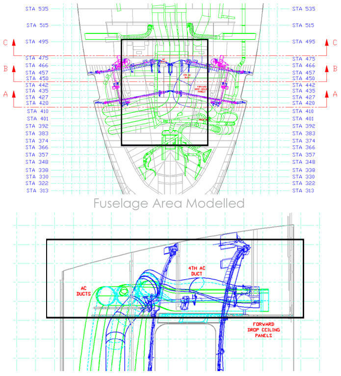
Conditioned air was delivered to the passenger cabin through four main distribution ducts: one duct on the left side of the aircraft and three ducts on the right side. The main distribution ducts supplied conditioned air to smaller individual air ducts. The left-side distribution duct comprised a fibreglass riser duct (PN ABM7623-1) and a rigid foam duct (PN ABM7536-1). The fibreglass riser duct was installed outboard of Galley 1 and extended vertically from below the floor to above the Galley 1 ceiling, running diagonally across the Galley 1 ceiling to terminate slightly aft of the rear inboard corner of Galley 1. The riser duct was wrapped in a single layer of MPVF-covered insulation blanket. The fibreglass riser duct connected with the rigid foam duct segment above the cabin ceiling, slightly aft and inboard of Galley 1 (STA 420, X= 28). The rigid foam duct segment ran horizontally aft from STA 420 to STA 478. The rigid foam duct was not insulated.
A small portion of the fibreglass riser duct, located near the cabin floor level, was identified and exhibited no heat or soot accumulation. None of the rigid foam duct segment was identified.
The riser assembly, consisting of three ducts, on the right side of the aircraft was installed outboard of Galley 2 and extended vertically from below the floor to above the Galley 2 ceiling. The riser duct assembly connected to a horizontal three-duct segment which extended aft, just above the forward cabin drop ceiling, from Galley 2 to STA 480. An insulation blanket with an MPET cover material was wrapped around the riser duct assembly. Inboard of the splice joint, the horizontal three-duct assembly had duct insulation with MPVF cover material. A separate insulation blanket with MPET cover material was installed around the joints between the duct assemblies, located between STA 392 and STA 427. Another insulation blanket with an MPET-type cover material was installed around the STA 480 joints at the aft end of the horizontal three-duct assembly.
The lower surface of the three-duct riser assembly exhibited a region of severe heat damage from X= −30 inboard to the joint at X= −20. The upper surface of this same assembly had areas of no heat damage.
A segment of duct (PN ABM7181-221), measuring 8.9 cm (3.5 inches) in diameter and 5.1 cm (2 inches) in length, branched off from the horizontal three-duct assembly and terminated at STA 407, X= 13, Z= 76. A silicone elastomeric end cap (PN 9D0068-0350) was installed over the end of this branch duct and held in place by an adjustable clamp. The end cap was covered with an MPVF-type cover material.Footnote 2 The branch duct and a large piece of the conditioned air duct to which it mates were recovered from the wreckage and reconstructed.
Both ducts exhibited severe heat damage consistent with damage seen on temperature reference coupons that were exposed to temperatures from 427 to 621°C (800 to 1 150°F) for 10 minutes; however, heat damage of this type could also be generated at higher temperatures over a shorter time interval.
Recovered portions of the horizontal three-duct segment exhibited areas of severe heat damage on the upper surfaces in the vicinity of the Galley 2 vent duct. This high heat areaFootnote 3 extended longitudinally from approximately STA 395 to STA 442 and laterally from X= 25 to X= −10. The lower surface of the same three-duct segment exhibited areas of undamaged FR primer from STA 408 to STA 442, X= 20 to X= −3. The upper surface of the centre duct in the segment exhibited an area of undamaged FR primer from STA 408 to STA 418, X= −10 to X= −17. The remainder of the horizontal three-duct segment between STA 442 and STA 480 was not recovered. A coated fibreglass cloth duct splice (PN IT-5043-162) was recovered and exhibited impact and localized heat and soot damage. The two possible locations for this duct splice were on the centre duct of the horizontal three-duct segment at approximately STA 401, X= −45 or STA 475, X= 5.
The passenger cabin conditioned air distribution ducts continued aft from STA 480 as four separate ducts. Between STA 480 and STA 520, the distribution ducts angled upward to run along the upper crown area. At STA 555, the forward end of the recirculation air duct joined the distribution duct for the forward cabin zone. The remaining three distribution ducts continued aft along the upper crown.
Recovered portions of the cabin conditioned air distribution ducts between STA 480 and STA 545 were characterized by undamaged FR primer on the lower surfaces of the ducts and a few small areas of severe heat damage on the upper surfaces of the ducts. This is the area in which the ducts transitioned from the forward cabin drop-ceiling structure upward to the crown.
The remaining cabin conditioned air distribution duct from STA 555 aft, including the muffler assembly at approximately STA 585, did not exhibit heat damage to the FR primer. The recovered portions of the two individual air ducts from approximately STA 555 to STA 595 at X= 70 and X= −70 did not exhibit heat damage to the FR primer but exhibited areas of light to moderate soot accumulation.
Recirculation air system fans and ducts
Recirculation air was supplied by four fans located above the passenger compartment ceiling at STA 685, STA 725, STA 1009, and STA 1109, each at lateral position X= 28. Each fan drew air through a filter and plenum assembly located at the corresponding station from X= 40 to X= 65. The plenum assemblies were reconstructed; the plenums that had been installed at STA 685 and STA 725 exhibited no discolouration of the FR primer on the aluminum parts but exhibited localized areas of heavy soot accumulation. The recovered portions of the fibreglass filter elements exhibited dark grey colouration on one side and light grey colouration on the opposite side. The hoses connecting these plenum assemblies to the fan housings exhibited localized, light soot accumulation on the outer surfaces but exhibited no soot accumulation on the interior surfaces. The recovered portions of the plenums from STA 1009 and STA 1109 did not exhibit heat damage or soot accumulation.
The recirculation duct was uninsulated between STA 569 and the recirculation fan at STA 685. A check valve was installed in the duct to prevent reverse airflow when the fan was not operating. Portions of the recirculation duct between STA 685 and STA 555, where it joins the cabin conditioned air duct, were recovered. The recovered pieces of recirculation duct exhibited severe heat damage on the uninsulated sections aft of STA 569.
Centre forward cabin individual air was supplied from the cabin recirculation air distribution duct at two locations: STA 575, X= 27 to STA 584, X= 2 and at STA 692, X= 20 to X= 9. Recovered portions of the duct from both of these locations exhibited severe heat damage.
Forward cabin individual air was supplied by a fan and plenum assembly that was identical to the recirculation air. The fan was located at STA 990, X= −24 and the plenum assembly was located between X= −40 and X= −65. The recovered portions of the plenum did not exhibit heat damage or soot accumulation. The individual air ducts were uninsulated and ran forward from STA 990 to a wye at STA 750, Z= 91, X= −21. One branch of the wye ran across the crown to the left side of the cabin (X= 76) and the other branch ran to the right side (X= −76). The recovered portions of these ducts exhibited moderate to heavy soot accumulations with no heat damage. The aft-most segment of individual air duct that was recovered was from STA 934 to STA 955 at X= −22; the duct segment exhibited light soot accumulation.
Cockpit headset
A melted portion of an ear piece from the boom microphone side of a cockpit headset was recovered. The ear piece was fabricated from a black polymer compound with a melting temperature of approximately 177°C (350°F). It could not be determined where the headset was located when the fire was in progress, although it was likely in the cockpit.
Cockpit carpet and seats
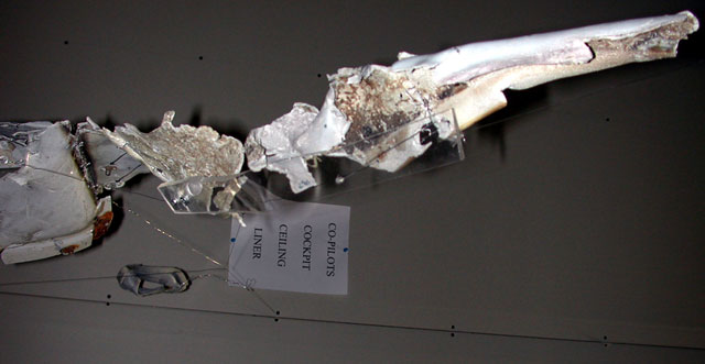
Recovered portions of the cockpit carpet included numerous areas with localized heat damage. The carpet exhibited an irregular, indented, spotted appearance at locations where the pile had been reduced to short stubble. Microscopic fibre analysis determined that the spotted areas had been produced by high-temperature material that had dropped onto the carpet from above. The carpet was fabricated from 100% wool. The wool fibre ends exhibited discolouration and bubbling indicative of burned wool hairs. No traces of the drop-down material were recovered. The brittle, burned fibre ends had broken off, most likely during impact, releasing the material that had fallen and adhered to the carpet fibre and leaving the short stubble patterns on the carpet. It was determined that the majority of the fibre drop-down damage was likely the result of the cockpit ceiling liner melting and dripping onto the carpet.
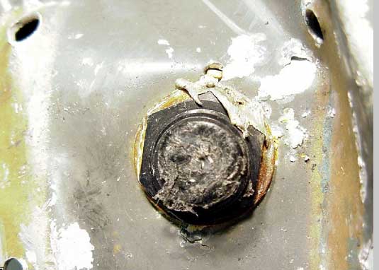
Several deposits were found on the right observer's seat. A small amount of resolidified 2024 aluminum alloy was deposited on the lap belt and on the right side of the seat base on a screw.
A small amount of resolidified 6061 aluminum alloy was found on the rear of the seat base on a CB.
When the resolidified aluminum was removed from the lap belt, a white deposit remained. Other white deposits were observed elsewhere on the same lap belt. Trace analysis of these white deposits identified their composition as being primarily aluminum oxide. Microscopic fibre analysis identified fused, heat-damaged lap belt material at each location where the aluminum oxide deposits were found. These other white deposits were determined to be from locations where molten aluminum had once been deposited. The precise alloy of the aluminum from these latter locations could not be determined. It cannot be determined at what point during the flight sequence, impact sequence, or both that these deposits were made.
Cockpit wall panels, door, and door jamb
The left and right rear cockpit wall panels, door, and portions of the door jamb were made from para-aramid fibre. The complete left rear wall panel was recovered. The forward-facing surface of this panel exhibited localized heavy soot accumulations on the top 46 cm (18 inches). The aft-facing surface of this panel exhibited no evidence of heat or soot damage. The complete right rear wall panel, which had been attached to Galley 2, was recovered. No evidence of soot was found on this panel, but localized black drips were found on the forward-facing surface of the panel. The majority of the drips were located between 28 and 79 cm (11 to 31 inches) from the top of the panel.
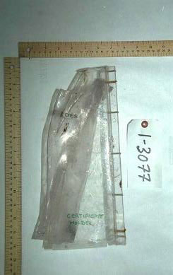
The cockpit door was located between the left and right cockpit rear wall panels. The main door panel comprised a para-aramid fibre panel with a honeycomb core, covered on both sides with resin impregnated glass fibre fabric facing. A decorative laminate was bonded to the forward-facing surface of the door. The lower portion of the door had a rectangular hole, measuring 81 x 41 cm (32 x 17 inches), to accommodate a louvred panel grill assembly (blow-out panel). The blow-out panel consisted of a forward and aft para-aramid fibre grill panel separated by polyurethane foam blocking and was enclosed in an aluminum frame. An aluminum cover was bonded to each of the para-aramid fibre grill panels; the exposed aluminum surfaces were covered with a decorative laminate. A clear, plastic, rectangular certificate holder, measuring 34 x 25 cm (13 x 10 inches) was mounted on the forward-facing surface of the cockpit door and centred approximately 69 cm (27 inches) down from the top of the door.
The main door panel was recovered. Small portions of the decorative laminate remained bonded to the forward-facing surface of the para-aramid fibre panel. A dark discolouration was evident on the upper third of the forward-facing surface of the door on both the exposed para-aramid fibre panel and the remnants of the decorative laminate.
Portions of the blow-out panel were recovered. The aluminum covering had separated from both the forward and aft para-aramid fibre grill panels; however, pieces of aluminum were identified as having been installed on the para-aramid fibre door grill panels. There was no evidence of heat damage or soot accumulations on the forward or aft para-aramid fibre grill panels or the aluminum covering. The certificate holder was recovered. The holder was deformed between the two vertical sides. An area of black discolouration, measuring 2.5 cm (1 inch) wide and 3.8 cm (1.5 inches) high, was observed near the lower right corner of the holder; the top edge of the certificate holder exhibited slight, melt-like characteristics.
Portions of the door jamb were recovered. The inner surface of the door jamb structure exhibited an area of heavy, soot-like discolouration located between 156 and 174 cm (64 to 68.5 inches) above the cockpit floor. This soot-like discolouration gradually diminished to a faint soot-like discolouration about 123 cm (48.5 inches) above the cockpit floor. Two portions of the left side door jamb were identified. Both portions, one identified as having been located between approximately 133 and 214 cm (52.5 to 84.5 inches) and the other between 199 and 214 cm (78.5 to 84.5 inches) above the cockpit floor, exhibited localized areas of moderate to heavy soot accumulation and evidence of heat damage.
The angle assembly installed across the top of the door jamb was identified. The angle assembly exhibited evidence of heat damage, including blistering and missing or discoloured paint.
A portion of the door frame fairing assembly, measuring approximately 24 cm (9.5 inches) wide, was identified as having been located between 150 and 197 cm (59 to 77 inches) above the cockpit floor level. The inner-facing surface of the upper end of the fairing exhibited discolouration that corresponded to oven test samples exposed to approximately 260°C (500°F) for 10 minutes. In addition, the grey finish canvas on the outer-facing surface, which was exposed to the cockpit, exhibited localized heat damage and soot accumulations.
Areas of resolidified aluminum
Several resolidified aluminum deposits were found on the outer surface of the cockpit conditioned air duct, at a position just aft of the smoke barrier. The precise alloy of this aluminum could not be determined by energy dispersive x-ray spectrography. Deposits of 6061 and 2024 aluminum alloy were identified on the top of the emergency lighting system battery pack, which was installed on top of the forward cabin drop-ceiling panel that was located immediately aft of the cockpit door.
Lavatories
Nine lavatories were installed in the aircraft. The tops of Lavatory A and Lavatory B were exposed to the area in which the fire occurred. Parts recovered from the remaining seven lavatories did not exhibit heat damage or soot accumulations.
Smoke detectors
A smoke detector control panel with short lengths of nine wires protruding through the cover was recovered and identified as the Lavatory A and Lavatory B smoke detector control panel. This panel was installed in the left forward cabin drop-ceiling area, adjacent to the inboard aft corner of Galley 1. Soot accumulations were found on the outer insulation of the nine wire segments. The outer surface of the panel cover exhibited heavy soot accumulations; however, the inner surface of the cover was free of soot. There was no evidence of heat damage or soot accumulation on the wiring and printed circuit boards inside the panel. A partially melted nylon wire support remained attached to the exterior of the panel.
Galley system
Twelve galley units were installed in the aircraft. Galleys 1, 2, and 3 were located forward of the first-class cabin; the upper surfaces of these galleys were exposed to the area in which the fire occurred, through a cut-out in the ceiling panels.Footnote 4 The galley structures were fabricated from meta-aramid fibre paper panels with fibreglass cover plates and extrusions bonded or rivetted to the panels. The top surface of the galleys was exposed to the area above the forward cabin drop-ceiling through a cut-out in the ceiling panels. The gaps between the galleys and the ceiling panels were filled with a foam material.
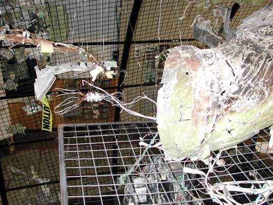
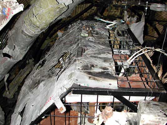
Galley 1 was installed on the left side of the forward cabin between the cockpit aft wall and the left forward cabin door. A large section, consisting of a number of portions of the upper surface of Galley 1 was identified. The upper surface of Galley 1 was horizontal across the top and curved along the left side to follow the contour of the fuselage. The upper surface of these portions, which had been exposed to the area in which the fire occurred, exhibited heavy soot accumulations and thermal discolouring of the paint on the upper surface. A support tube and mounting bracket attached to the top of the galley also exhibited areas of heavy soot accumulation. Near the aft end of the horizontal portion of the upper surface of Galley 1, there was a diagonal region that was relatively clean and undamaged. This region corresponds to the area located below the fibreglass riser duct (PN ABM7623-1), which may have protected this area during the fire. The soot and heat damage ended abruptly on the curved portion of the upper surface, forming a horizontal line at an elevation corresponding to where the 5.1 cm (2-inch) flexible hose (PN S7929462H-8-136) and the 7.6 cm (3-inch plenum hose (PN S7929462H-12-72) connect to the galley vent duct.
Two electrical connectors from the Galley 3 disconnect assembly were recovered. Both connectors exhibited areas of localized soot accumulation. Six 16 AWG wires and two 20 AWG wires remained in one insert grommet. The outer polyimide insulation on several of these wires exhibited areas of heavy soot accumulation and discolouration. The discolouration of the wire insulation corresponded to a wire test sample that was heated in an oven at approximately 522°C (972°F) for 7.5 minutes.
Cabin and emergency lights
Emergency exit signs were installed in the aircraft above the doors and in the drop-ceiling header immediately aft of Lavatory A and Lavatory B. A piece of an exit sign lens from the forward cabin drop-ceiling area was recovered. The lens exhibited heat damage; there was a hole in the lens with melting and wrinkling around the edges of the hole. A piece of gasket-like material remained attached to the edge of the lens; the gasket material exhibited localized areas of dark brown to black discolouration and thermal shrinkage.
Three fluorescent light fixtures were installed in the forward cabin drop-ceiling panels. Two pieces of the fluorescent light lens material were recovered. Both pieces of the lens material exhibited heat damage, including localized thinning of the material accompanied by melt wrinkles and tight folds, thermal discolouration, and soot accumulation.
Light fixtures were installed in the ceiling bridge panels above the aisles in the main cabin to provide aisle lighting and emergency lighting. Each fixture contained two lights: an inboard emergency light and an outboard aisle light. Portions of ceiling bridge panels were recovered with localized, circular, dark discolouration around the cutout for the outboard aisle light. The areas of the ceiling bridge panel adjacent to the inboard emergency light were not heat damaged or discoloured. An exemplar aisle light fixture was removed from an in-service MD-11. This latter assembly exhibited melt-like deformation on the inside surface of the clear lens portion, heat damage to the associated sealant, and an amber discolouration of the clear lens. The lower surface of the lens assembly that faced into the cabin was not discoloured or thermally deformed.
Avionics CB panel
The avionics CB panel, situated above the work table at the right observer's station, consisted of an upper and lower panel, both of which were fabricated from 0.1 cm (0.05-inch) 6061-T6 sheet aluminum and painted grey on the side that faces into the cockpit. The upper avionics CB panel was installed at an angle to the vertical with the upper edge farther inboard than the lower edge. The lower avionics CB panel was mounted vertically, directly below the upper panel.
The CB terminal from the IFEN DC CB at position F-1 was recovered; the 16 AWG jumper wire was still attached to the terminal and to segments of the DC Bus 2 feed wires. The CB contact was not heat damaged or pitted; the jumper wire was not heat damaged but trace accumulations of soot were present on the wire. The jumper wire remained attached to the bus feed wire that had been installed at positions F-2, F-3, and F-4; the CB terminals from positions F-2 and F-3 remained attached to these wires. There was no indication of heat damage or electrical arcing on the DC bus feed wires or on the F2 and F3 CB terminals; however, trace amounts of soot accumulation were observed on these components.
The high heat damage on the front surface of the panel near the aft end (just forward of STA 383) is not seen at a corresponding location on the back surface. Items adjacent to the back surface in this area are in relatively good condition, such as the recovered pieces of the power wires and portions of the 28 V AC 1 bus bar, the grey sleeving and power wire assembly for 115 V AC Bus 1 associated with bus bar assembly items B7-12 and B7-13.
The back surface of the panel near this location shows little heat damage, as noted above. A fire initiating on the over-frame MPET-covered insulation material would not generate high heat during its incipient stage of growth. High heat would not be expected until the fire had spread elsewhere, and grown in intensity. The heat patterns observed on the upper avionics CB panel and elsewhere in the cockpit are indicative of secondary damage created by the fire much later during the fire sequence.
The high heat damage evident on the front face of the upper avionics CB panel essentially forms the outline of two areas: an irregularly shaped band that is primarily horizontal along the upper edge of the panel and another irregularly shaped region, which is offset at a diagonal angle. The patterns are consistent with secondary fire damage likely produced by the combined effects of the cockpit ceiling liner being breached (between the right overhead diffuser and the upper inboard edge of the avionics CB panel) and the effects of the overhead duct assembly, which is routed to the right cockpit window defroster, acting as a fire barrier.
Failure of the ceiling liner would allow combustion by-products to be drawn into the cockpit by being entrained into the conditioned air stream being blown out of the right overhead diffuser toward the front face of the avionics CB panel. This could cause the high heat damage pattern observed on the front face along the top edge.
The outline of the diagonal heat pattern corresponds with the diagonal path of the right window defroster duct assembly that is routed behind the avionics CB panel. This duct assembly, and a portion of the right cockpit individual air supply assembly, would be expected to act as a diagonal fire barrier dividing the air space behind the panel in two. The high heat damage patterns found on both the front and back sides of the upper avionics CB panel forward of the diagonal, and the high heat damage present on the aircraft frames in this localized area, are consistent with damage generated by high-temperature combustion by-products being directed into this confined region. The lesser degree of heat damage aft of the diagonal duct assembly is consistent with a lower heat build up in that area. This lesser heat damage is likely the result of factors, such as the larger air space volume behind the panel in this region and the air flow being evacuated down the ladder area.
The CBs for the first three FDR recorded events associated with electrical circuit failures are located at the forward end of the avionics CB panel in an area where high-temperature damage is evident. It is significant to note that these events took place approximately 13 minutes after an unusual odour was first detected in the cockpit, which was late in the fire sequence. The timing of these events and the location of the associated CBs are consistent with the report’s description of the fire initiation and growth sequence.
The two 115 V AC Bus 1 power wires for phases B and C, as well as the 115 V AC Bus 1 power wire for phase A, were 8 AWG nickel-coated wires. These wires were wrapped in polyimide tape with an outer aromatic polyimide braid. The wires were placed inside a grey sleeving for a portion of their lengths. The sleeving consisted of a glass fibre braid with a silicone elastomer coating.
Overhead panel
The overhead panel area is located in the centre cockpit ceiling between the captain's and first officer's seats. The overhead panel contains system control panels in the forward portion, engine fire detection and shutoff in the middle portion, and the overhead CB panel in the aft portion. The cavity behind the overhead panel is contained within a fibreglass housing. The housing contains wiring routed to the control panels, module block strips, and ground studs.
The overhead panel wires enter and leave the housing through one of two oval holes located on the left and right side of the aft wall of the housing. System wires that leave the housing through the left side oval hole are primarily in wire run AML and are routed aft above the cockpit ceiling. The recovered segments of the AML wire run extended up to 76.2 cm (30 inches) aft of the oval hole. System wires that leave the housing through the right side oval hole are primarily in wire run AMK and are routed either aft above the cockpit ceiling or outboard of the avionics CB panel. The recovered segments of the AMK wire run extended up to 8.5 inches aft of the oval hole. The overhead CB panel bus feed wires also exited through the right side oval hole. These wires were routed aft along the left side of the CB panel, across the aft end of the CB panel, and through the right side oval hole in the aft end of the housing. Recovered segments of the overhead CB panel bus feed wires extended up to 25 inches aft of the right housing oval hole.
The overhead CB panel was approximately rectangular. The lower (cockpit-facing) side of the panel was painted grey; the upper surface of the panel was not painted. There were seven rows of CBs on the panel, labelled alphabetically from A to G, with "A" representing the rear-most (aft) row. CBs in each row were numbered sequentially from left to right. A lighted plate assembly was installed above each row of CBs.
Approximately 90% of the overhead CB panel was recovered. The grey paint and primer on the cockpit-facing surface of the panel was missing from an area measuring 4 square inches on the aft right corner of the panel. The bare aluminum corresponded to an oven test sample temperature of 427°C (800°F) (or greater) for 10 minutes. The paint and primer forward of this area was discoloured. This discolouration corresponded to an oven test sample that was exposed to 353°C (650°F) for 10 minutes. Heavy black soot accumulations surrounded the areas of bare metal and discoloured paint. This black soot accumulation continued forward along the side of the panel to the bottom of the Row C light plate. The grey paint on the remainder of the cockpit-facing surface of the panel was not discoloured. The upper surface of the panel that faced into the overhead housing was not painted; however, a heat pattern was visible on the upper surface on the aft right corner of the panel. The polycarbonate base for a light plate assembly was recovered with the aft panel portion. The Row A light plate base exhibited extensive melting and thermal deformation; some CB buttons and springs were entrapped in the melted area. Light plate assemblies corresponding to rows located farther forward in the overhead CB panel exhibited progressively less thermal damage.
A segment of wire harness from the CVR control panel was recovered. A two-conductor shielded wire and a 24 AWG wire exhibited black discolouration on the polyimide insulating film; the copper conductor was not embrittled or melted. The black discolouration of the polyimide film was consistent with damage to an oven sample that was exposed to approximately 510°C (950°F) for 7.5 minutes. The area of heat damage was approximately 6 cm (2.5 inches) forward to 13 cm (5 inches) aft of the oval hole on the right side in the aft end of the housing assembly. Additional wire harnesses and components from the overhead panel were recovered and analyzed. This analysis resulted in numerous and consistent indications of temperatures exceeding 482°C (900°F) for several minutes in the area of the right oval hole in the aft wall of the housing. The region of high temperature extended aft for several inches from the right oval hole in the housing.
Smoke in the cockpit study
In December 1998, the FAA Safety Analysis Branch reviewed all airline incidents investigated by the NTSB and 475 000 SDRs from 1986 to September 1998. The review identified 2 514 SDRs and 10 NTSB incident reports that were considered to be representative of incidents of smoke in the cockpit. The reports addressed the entire USA fleet of air transport category aircraft and the majority of regional aircraft with 20 seats or more. A review of the FAA study conducted on USA airline aircraft revealed the following points with respect to "smoke in the cockpit" events:
- In one third of the reports, there was no smoke at all; these events were caused by faulty smoke detectors, burning oil stains from earlier maintenance and most commonly, from foul-smelling air conditioning bags that flight crew members interpreted as smoke.
- Air conditioning systems were the most common source of reported incidents, accounting for 36.7% of the reports; in most cases, there was no smoke at all. However, these reports resulted in 30 diversions per year and 3 to 4 evacuations per year.
- Interior lighting accounted for 14% of the reports. These reports resulted in four diversions per year and no evacuations.
- Anti-ice and heating systems for windows and doors accounted for 9.7% of the reports.
- Electric power systems, including APUs, accounted for 8.5% of the reports.
- Navigation systems, such as on-board computers, altimeter encoders, and weather radar systems accounted for 7.3% of the reports.
These categories of smoke events accounted for 77% of all SDRs involving smoke in the cockpit. From 1994 to September 1998, the average annual US commercial aircraft fleet size was approximately 6 110 aircraft. During this time period, there were approximately 256 reports per year of smoke in the cockpit, 30 of which resulted in a diversion. These figures equate to one smoke in the cockpit event for every 24 aircraft per year and 1 diversion for every 203 aircraft per year. If aircraft were diverted for every smoke in the cockpit event, this would result in 256 diversions per year for 6 110 aircraft or one diversion per 24 aircraft per year. As the world fleet comprises approximately 18 000 aircraft, assuming the same diversion ratio for the world fleet as for the US fleet, this ratio would mean 754 diversions worldwide per year.
Burn tests
Small-scale burn tests
In the MD-11, thermal acoustic insulation blankets were installed with hook-and-loop fasteners. The seams between adjoining blankets were sealed with MPET-type 5 splicing tape constructed with MPET or MPVF material and coated with adhesive. Small-scale burn tests were conducted to determine the flammability characteristics of MPET-covered insulation blankets, hook-and-loop fasteners, and adhesive tape. Additional tests were conducted to determine the ignition and flame propagation characteristics of these and other aircraft materials.
Hollow tube "Jellyroll" burn test
Preliminary attempts were made to ignite MPET-covered insulation blankets with a Bunsen burner as an ignition source. It was observed that the outer film would shrink away from the ignition source, allowing the film to self-extinguish. However, if the insulation material was formed into a jellyroll shape with a hollow centre, and a small pilot flame was introduced within the tube, the film material would ignite and propagate consistently over the inner surface of the tube. Much of the film covering the outer surface of the tube was also consumed.
This configuration enabled the cover film on the inside radius of the jellyroll to be significantly pre-heated, which was observed to be an important factor affecting the fire behaviour of the cover material. There were significant changes in the burn rate, heat release rate, and propensity to self-extinguish. The material was less inclined to self-extinguish. Although MPET-covered insulation blankets were generally easier to burn than the MPVF-covered insulation blankets, the flammability of both types of cover material increased when the material was pre-heated.
Video – Hollow tube burn test
Electrical wire arc tests
A review of the relevant literature indicated that AES may be used to differentiate between an arc that initiated a fire (arcing in a clean environment) and one that resulted from a fire (arcing in a contaminated or smoky environment). The TSB investigated whether it was possible to make this determination with some degree of accuracy. As the literature referred only to copper melts generated by arcs using household types of wire insulation, the TSB initiated a study using aircraft type wire insulations.
The primary aircraft wire insulation used in the MD-11 was MIL-W-81381, a polyimide-wrapped, nickel-coated copper conductor. The primary insulation material used on the IFEN system power wiring was an ETFE, tin-coated copper conductor. As some segments of each of these two types of insulated wires were recovered with copper melt damage, the study focused on these two types of wire insulation.
To provide copper melts and beads for the AES study, TSB investigators created a number of arcing events, under controlled conditions, at the Boeing Electrical Laboratory in Seattle. The copper melts were generated by first breaching the insulation and then using either an aluminum bar (to simulate aircraft structure) or an uncoated copper drag wire to short circuit the wires. Other arcs were created by exposing the insulated conductors to burning aircraft materials and then applying a direct flame source, using a Bunsen burner, to simulate arcs created in a fire environment. Various combinations of the insulation types were used to generate copper melts with each type of insulation using both 115 V AC 400 Hz and 28 V DC power sources. A sampling of these copper melts was then provided for AES examination in a blind study (i.e., the origin of the copper melt was not disclosed until after the study was complete).
Video – Electrical wire arc tests - polyimide insulation
Video – Electrical wire arc tests - ETFE insulation
MPET-covered insulation with splicing tape and hook-and-loop fastener
A piece of MPET-covered thermal acoustic insulation blanket material was selected from MPET Lot Number 2007 (Exhibit 1-14672). This piece was chosen because it had an area of cover material that had MPET and MPVF-covered tape adhered to it. A strip of hook-and-loop fasteners was in contact with cover material on one side and in contact with MPET-covered tape on the other side. The piece was laid on top of a piece of yellow fibreglass batting that came from an insulation blanket from the same lot number.
On 7 December 2001, the cover material was ignited using a small flame from a butane lighter at a corner of the specimen. A small, creeping fire (with a flame height measuring approximately 1 to 2.5 cm (0.5 to 1 inch)) was observed to burn across the specimen. The flame front came in contact with MPET-covered tape at a number of different locations. In every case, the flame front ignited the MPET-covered tape, the flame front noticeably increased in size (with the flame height sometimes reaching 17.5 cm (7 inches)) and the flame spread rate slowed. The burning cover material produced a significant amount of smoke; however, the MPET-covered tape produced much more smoke and burned with greater intensity and duration than the cover material alone. The flame front came in contact with MPVF-covered tape at two locations. In both cases, the MPVF-covered tape ignited with no apparent difficulty. The flame size increased slightly and the flame-spread rate did not change. In the case of the MPVF-covered tape, the flame size was similar in height to the previous flame (approximately 1 to 2.5 cm (0.5 to 1 inch)). When the flame front contacted the hook-and-loop, it did not ignite the material and the flame extinguished. When the flame front contacted the MPET-covered tape next to the hook-and-loop fastener, it once again ignited the MPET-covered tape; the burning tape subsequently ignited the hook-and-loop material. A second piece of MPET-covered insulation blanket material was selected from MPET Lot Number 2007 (Exhibit 1-14677). The test procedure was repeated and the same results were observed.
Video – Hook-and-loop burn test
Silicone elastomeric end cap
A small-scale burn test was also conducted on a silicone elastomeric end cap, identical to the cap that had been used to terminate the Galley 2 vent duct. The test demonstrated that the end cap could be easily ignited with a small flame. Once ignited, the end cap material was consumed by a self-propagating fire that produced a soft white ash; the ash residue disintegrated when touched. Similar results were obtained when the test was repeated using silicone elastomeric end caps that were recovered from the wreckage of the occurrence aircraft.
Cone and micro-calorimeter tests
Heat release and heat-release rate are key parameters in assessing the fire development characteristics of a material in a fire, particularly in an enclosed area. The cone calorimeter exposes a test sample to radiant heat fluxes and measures the sample's heat release rate, total heat released, and effective heat of combustion using the oxygen consumption principle.Footnote 5 The micro-calorimeter uses the same principle to measure the heat release rate of much smaller samples that are pyrolysed in an inert gas stream and subsequently combusted in an oxygen-rich environment.
The thermal energy released by the combustion of various aircraft materials was measured using a standard cone calorimeter and a micro-calorimeter. These data were used in the development of a computer-based fire model for the MD-11.
Intermediate-scale burn test
Intermediate-scale burn tests were conducted at the US FAA Technical Center in Atlantic City, New Jersey, in November and December 2001. The purpose of these tests was to characterize the flammability properties of Insulfab 350, DMS 2072K, Type 2, Class 1, Grade A, MPET-covered thermal acoustic insulation blankets, particularly when the blankets are pre-heated before being exposed to an ignition source.
Video – MPET-covered insulation blanket burn test
The second objective of the test was to characterize the flammability and heat-release properties of the rigid foam air distribution duct, which had been installed in the occurrence aircraft. No portion of this duct was identified in the wreckage, but another duct with the same specifications was obtained from another airline.
Test method
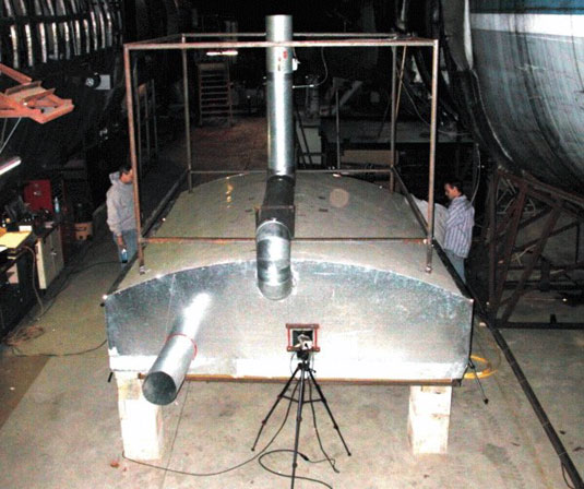
The burn rig was constructed from a section of B747 fuselage to simulate the MD-11 fuselage between STA 364 and STA 501. The rig was 348 cm (137 inches) long and 287 cm (113 inches) wide, and was raised off the concrete floor on cinder blocks. The ends of the burn rig were closed, but 25-cm (10-inch) ducts were installed at each end at the crown (top) of the rig. An electric exhaust fan was used to draw air through the ducts at both ends of the rig to simulate the ends being open. The fan speed was controlled by a rheostat and the exhaust gases were monitored for oxygen levels. The heat release properties of the burning materials was derived from the amount of oxygen depletion in the exhaust gases.
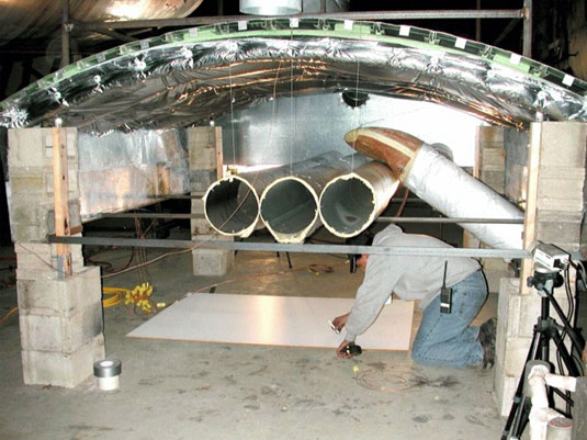
Two layers of Insulfab 350, DMS 2072K, Type 2, Class 1, Grade A, MPET-covered insulation were installed in the burn rig to simulate the between-frame and over-frame insulation in the aircraft. The insulation blankets were provided by Swissair and were identical to the blankets that had been installed in the occurrence aircraft. Two pieces of flat stock were installed in the rig to simulate door tracks. Frames were installed in the rig; however, the frames were spaced 50 cm (20 inches) apart, whereas the frames in the aircraft were spaced 20 to 23 cm (8 to 9 inches) apart. The rigid foam duct was installed in the burn rig and ducts were attached to both ends. The adjoining ducts were wrapped in Orco film AN 18R PVF-covered insulation blankets, similar to the installation in the MD-11. A blower motor was attached to the end of the duct to provide airflow through the duct assembly. Three 35-cm (10-inch) ducts were installed in the burn rig to simulate the three conditioned air riser ducts on the right side of the fuselage. These ducts were wired together and were covered with a single layer of insulation material. Ceiling panels were installed within the burn rig to simulate those installed in the aircraft. Thermocouples were installed at numerous locations within the burn rig. Camera ports were installed in the burn rig for conventional and infrared photography.
Test procedure
Burn tests were conducted on the rigid foam duct. When the duct was not pre-heated it did not ignite. When the duct was pre-heated it ignited and produced a small, low-intensity flame that yielded relatively low thermal energy. It was concluded that the rigid foam duct did not contribute significantly to the thermal energy produced by the in-flight fire on the aircraft.
Burn tests were conducted in the test rig using Insulfab 350, DMS 2072K, Type 2, Class 1, Grade A, MPET-covered insulation blankets. The tests were initiated by igniting the cover material with a barbeque lighter. The Insulfab 350 insulation material ignited and developed into a robust and self-sustaining fire when the insulation material was pre-heated. Pre-heating was therefore assessed to be a significant factor affecting the flammability of the composite foam duct and the Insulfab 350, DMS 2072K, Type 2, Class 1, Grade A insulation blankets.
A bulk burn test was conducted by igniting approximately 500 square feet of Insulfab 350, DMS 2072K, Type 2, Class 1, Grade A insulation material in the burn rig. An intense and robust fire developed that generated large amounts of black smoke and melted sections of the aluminum frames.
Full-scale burn tests
Full-scale burn tests were conducted at the US FAA Technical Center on 5 May 1999, in the attic area of a DC-10 fuselage aft section.
Test method
The test section was approximately 18-feet long and was instrumented with thermocouples, smoke metres, calorimeters, and gas sampling equipment. Ceiling panels, with flammability characteristics similar to those in the occurrence aircraft, were installed. Two layers of MPET-covered thermal acoustic insulation blankets were installed in the attic area above the ceiling. One layer was installed between each frame of the fuselage against the skin of the aircraft; the second layer was installed over the first layer of insulation and over the frames. The seams between the second layer of insulation blankets were sealed with MPET-covered insulation splicing tape. The insulation blankets were constructed with MPET-type cover material bearing the marking Insulfab 350, DMS 2072L, Type 2, Class 1, Grade A. This material was of a different revision letter (L versus K) than the MPET-type cover material that had been used in the occurrence aircraft.
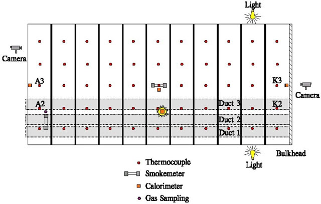
Three metal tubes representing conditioned air ducts were installed above the ceiling panels along the length of the fuselage test area. The ducts ran parallel to each other and were offset to one side of the fuselage longitudinal centreline. The ducts were open at both ends. Each metal tube was wrapped in a single layer of MPET-covered insulation blanket material.
Thermocouples were placed between each frame and situated to measure the temperature at the inward-facing surface of the over-frame blanket. Wide-angle video cameras were situated at both ends of the overhead area. Two fire calorimeter sampling points were located above the ceiling to measure heat release. Equipment for measuring smoke density was also installed in the test fixture.
Four air sample tubes were arranged vertically, one above the other, in the passenger cabin. Three of the tubes were used to collect samples to monitor CO, CO2 and O2 concentrations. The fourth tube was used to collect smoke samples for capillary gas chromatograph and mass spectrometer analysis. The FAA Civil Aeromedical Institute subsequently identified 13 aromatic compounds as being combustion by-products of the fire, including napththalene, biphenyl, 1-methyl naphthalene, 2-methyl naphthalene, 1-ethyl naphthalene, acenaphthalene, and various structural isomers of dimethylnaphthalene. These compounds are known to cause nausea and confusion and irritation to the eyes, skin, and respiratory tract. In addition, at temperatures above 204°C (400°F), hydrogen fluoride is evolved from MPVF-covered insulation blankets, such as those installed on the occurrence aircraft. Inhalation of low concentrations of hydrogen fluoride can induce coughing, choking, and irritation of the eyes, nose, and throat.
Test procedure
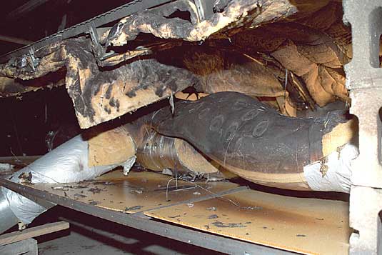
A fire was ignited by first igniting a piece of urethane foam measuring 10 x 10 x 46 cm (4 x 4 x 18 inches) that had been soaked at one end in 10 cc of heptane. The foam piece was placed above the ceiling between two ducts. The foam burned for approximately two minutes before being consumed by the fire. Follow-on tests were conducted using a smaller ignition source.
The fire spread from the ignition source to the ducts and to the overhead insulation blankets. The fire spread was slower and the flame height was smaller than observed during the intermediate scale tests. The fire primarily followed the insulation on the ducts and intermittently extended onto the overhead insulation blankets above the ducts. Pieces of flaming MPET-type cover material dropped from the ducts and overhead area onto the ceiling panels below; however, the ceiling panels did not burn. Flame spread onto the overhead insulation was limited to the regions adjacent to the ducts. The fire self-extinguished once the insulation blanket covering the ducts had burned away. A large amount of smoke was produced by the fire.
The test rig was modified to create an air gap between the two layers of Insulfab 350 insulation. A small flame was introduced between the two layers of insulation near the crown area of the fuselage. The flames were more intense than those observed in the earlier full-scale tests and spread between the two layers of insulation over a large area. Flames were observed emanating between the seams that joined the insulation blankets together. Significant amounts of smoke were produced by the fire.