Associated links (A98H0003)
Fire protection system
Portable fire extinguisher system
Description
There were six Halon 1211 fire extinguishers and two dry chemical fire extinguishers onboard SR 111. Halon extinguishers consist of a cylinder, a valve head, a carrying handle, a locking pin, a nozzle, and a pressure gauge. The dry chemical extinguishers consist of the same components, but have a flexible hose connecting the discharge head and the nozzle. All of the portable fire extinguishers were manufactured by General Fire Extinguisher Corporation. The fire extinguishers are not serialized and no record of their specific location within the aircraft is recorded, nor is there a requirement to do so.
Examination
Five of the six Halon 1211 fire extinguishers and both dry chemical fire extinguishers were recovered. The Halon extinguishers were identified by model GH-2 1/2 J Halon 1211 and the dry chemical were identified by model TCP5LH.
The fire extinguishers were examined to determine whether they were still charged, to assess their pre-impact charge state, and to determine whether they had been removed from their mounting brackets.
Recovered halon extinguisher exhibit 1-7150
Recovered halon extinguisher exhibit 1-7150 examination
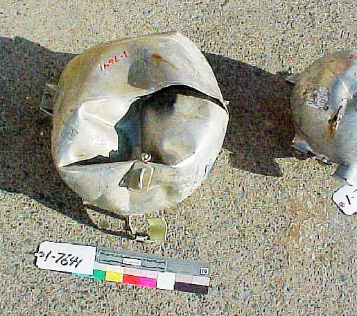
The cylinder was crushed and the complete valve head assembly (including the trigger, carrying handle, nozzle, pressure gauge, and locking pin) had torn off and was not recovered, leaving a hole in the cylinder. The cylinder weighed 1.90 lb.
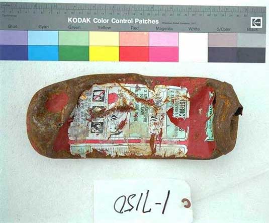
Recovered halon Eextinguisher exhibit 1-7150 determination
Damage to the unit precluded determining the pre-impact charge state. Due to the extensive damage to the bottle, it could not be determined whether the bottle was installed in its mounting bracket at the time of impact.
Recovered halon extinguisher exhibit 1-7151
Recovered halon extinguisher exhibit 1-7151 examination
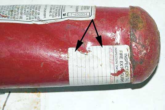
The cylinder was dented and partially crushed. The head assembly had been torn off and was not recovered, leaving a hole in the cylinder. The model T650554 was visible on the UL label. An inspection date of "11.5.98" was noted on the label along with the Swissair control decal with the alphanumeric combination "35031V-SR" printed on it. The cylinder weighed 2.13 lb. The cylinder exhibited an impact mark in the upper left-hand position.
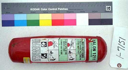
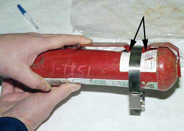
Recovered halon extinguisher exhibit 1-7151 determination
Based on the position of the impact mark on the cylinder, it was determined that the mark resulted from contact with its mounting bracket. This damage is consistent with the bottle being installed in the mounting bracket at the time of impact.
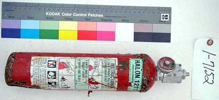
Recovered halon extinguisher exhibit 1-7152
Recovered halon extinguisher exhibit 1-7152 examination
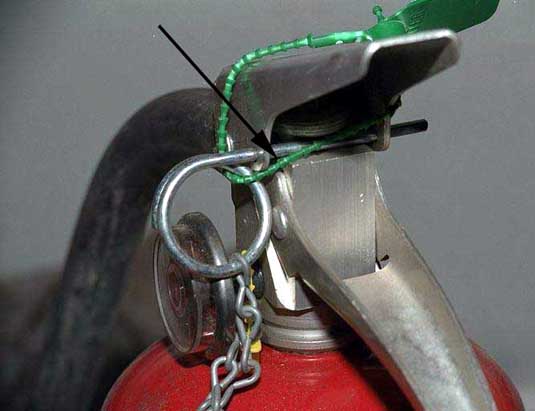
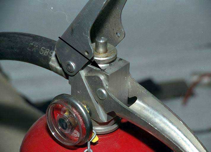
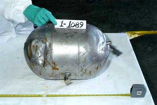
The cylinder was dented and the valve head was still attached to the cylinder. The trigger, carrying handle, nozzle, and locking pin were not recovered. The pressure gauge was still attached to the cylinder with the indicator reading at the top of charge zone. The cylinder weighed 4 lb, 8 oz.
To determine whether the extinguisher was still charged, a trigger and nozzle were installed and the fire extinguisher was discharged into a closed system recovery storage tank. A normal discharge occurred, lasting approximately 20 seconds. After discharge the cylinder weighed 2 lb, 8 oz, indicating that 2 lb of Halon had been discharged. The valve assembly was removed after discharge and the interior of the cylinder was examined. The bottom of the cylinder was lightly corroded, the remainder of the interior was clean, and a small amount of liquid Halon was visible inside the cylinder. The cylinder exhibited an impact mark. The discharge nozzle exhibited gouging at the point of contact with the locking pin.
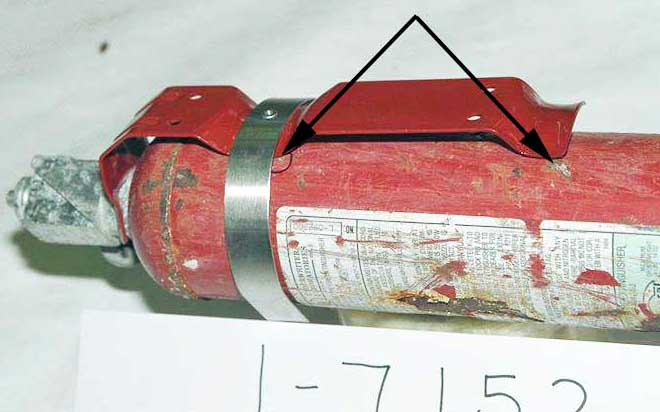
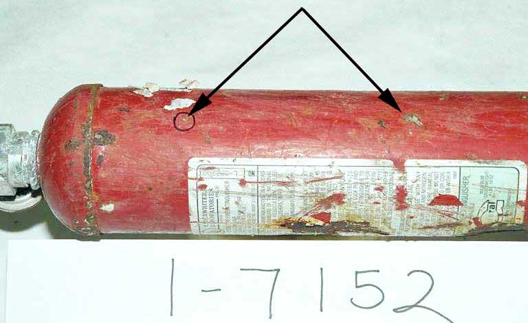
Recovered halon extinguisher exhibit 1-7152 determination
It was determined that the fire extinguisher was charged at the time of impact. Based on the position of the impact mark on the cylinder, it was determined that the mark resulted from contact with its mounting bracket. It was therefore determined that the bottle was installed in the mounting bracket at the time of impact. Based on the gouge marks on the discharge nozzle at the point of contact with the locking pin it was determined that the locking pin was installed at the time of impact. The noted physical damage is consistent with the fact that the fire extinguisher was still charged after impact.
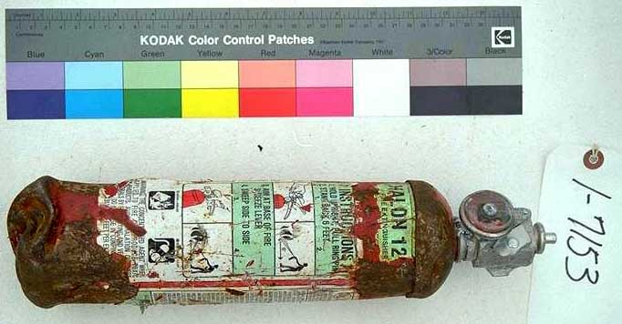
Recovered halon extinguisher exhibit 1-7153
Recovered halon extinguisher exhibit 1-7153 examination
The cylinder was heavily dented on the bottom and the valve head was still attached but the trigger, carrying handle, nozzle, and locking pin were not recovered. The pressure gauge was at the low end of the overcharge zone. The service and control tags were not readable owing to impact damage. The cylinder weighed 4.64 lb.
To determine whether the extinguisher was still charged, the trigger rivet was removed, a trigger and a nozzle were installed, and the extinguisher was discharged into a closed storage tank. A normal discharge occurred, lasting 18 seconds. The trigger and nozzle were removed and the cylinder weighed 2 lb, 4 oz, indicating that 2 lb, 7 oz, of Halon had been discharged. The valve was removed after discharge and the interior of the cylinder was examined. The interior was clean but the siphon tube was detached from the valve adapter. The cylinder exhibited impact marks at the lower left hand position. The discharge nozzle exhibited no impact marks resulting from contact with the trigger locking pin.
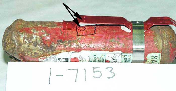
Recovered halon extinguisher exhibit 1-7153 determination
It was determined that the fire extinguisher was charged at the time of impact. Based on the location of the impact marks on the cylinder, it was determined that the marks resulted from contact with its mounting bracket attachment screw, at the lower left-hand position. This damage is consistent with the bottle being installed in the mounting bracket at the time of impact.
Recovered halon extinguisher exhibit 1-7154
Recovered halon extinguisher exhibit 1-7154 examination
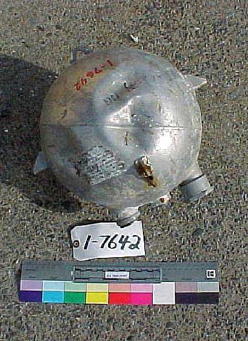
The cylinder was dented and the valve was still attached. The pressure gauge was loosely attached but the trigger, carrying handle, nozzle, and locking pin were detached. The service and control tags were not recovered. The cylinder weighed 2.18 lb, indicating that the cylinder was empty of Halon.
The valve was removed and the interior of the extinguisher was examined. The bottom and the walls of the cylinder were lightly corroded, which is not unusual. There was a small amount of loose oxide material on the interior of the cylinder. There was no sea water in the cylinder. The siphon tube was loose on the valve adapter. The corners of the valve block, adjacent to where the safety pin would normally sit, were undamaged.
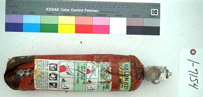
Recovered halon extinguisher exhibit 1-7154 determination
It could not be determined whether the extinguisher was charged prior to impact.
Recovered dry chemical extinguisher exhibit 1-7155
Recovered dry chemical extinguisher exhibit 1-7155 examination
The top of the cylinder was punctured and a piece of plastic sheet was captured in the hole. The valve, trigger, carrying handle, flexible hose, nozzle, and locking pin were not recovered. The cylinder weighed 4.86 lb. The cylinder also exhibited impact marks.
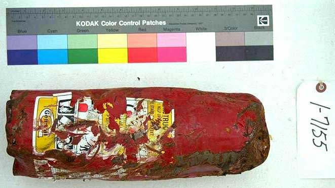
Recovered dry chemical extinguisher Exhibit 1-7155 determination
Based on the position of the impact marks, it was determined that the marks resulted from contact with the mounting bracket attachment screws. This damage is consistent with the bottle being installed in the mounting bracket at the time of impact.
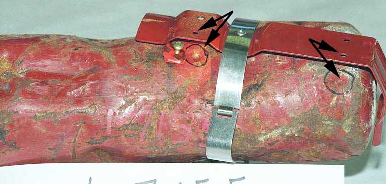
Recovered dry chemical extinguisher exhibit 1-7156
Recovered dry chemical extinguisher exhibit 1-7156 examination
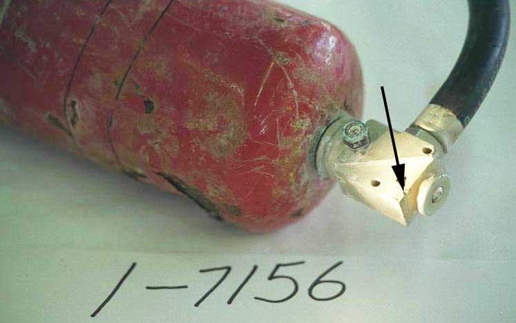
The cylinder was dented and the valve, hose, and nozzle were still attached. The trigger, carrying handle, pressure gauge, and locking pin were detached. The cylinder weighed 10.30 lb. According to a tag on the cylinder, it was last inspected on 11 May 1998. The Swissair control label exhibited the alphanumeric SN-NSN, 36201SV-SR. A piece of masking tape on the cylinder read Doghouse 9 RH. The valve body was displaced from an apparent side load and the top of the cylinder was partially collapsed on one side and bulged on the other. The corners of the valve head, adjacent to the locking pin, exhibited gouge marks. The valve was removed and there was no evidence of chemical agent or propellent discharge around the O-ring. The cylinder was full of the chemical agent up to the cylinder neck. The plastic fill tube was detached from the bottom of the valve. The bottle exhibited scoring in the area of the mounting bracket strap, but no mounting bracket damage could be identified. The discharge nozzle exhibited impact marks.

Recovered dry chemical extinguisher exhibit 1-7156 determination
The gouge marks on the corners of the valve are consistent with the pin being in place at the time of impact. Based on the noted damage, it was determined that the cylinder had not been discharged prior to impact. Since no damage to the mounting bracket could be identified, it could not be determined whether the bottle was installed in the mounting bracket at the time of impact. Based on the location of the impact marks on the discharge nozzle it was determined that the marks resulted from contact with the locking pin, indicating that the locking pin was installed at the time of impact.
Engine/Cargo/APU fire detection and suppression systems
General description
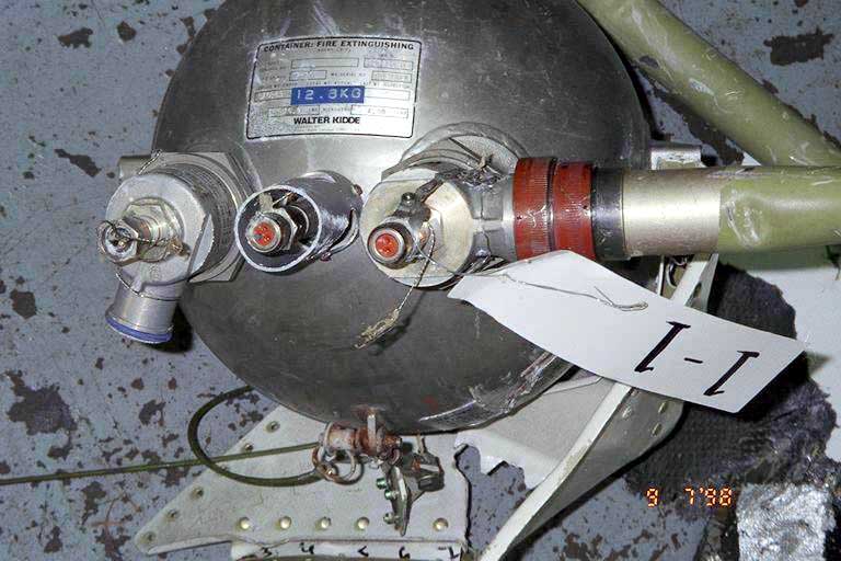
The aircraft was equipped with six engine, one APU, and two cargo bay fire suppression agent bottles. The Engine 1 and Engine 3 systems were each fitted with two bottles in the corresponding wings. The Engine 2 system had two bottles located below Engine 2 in the aft accessory compartment. The Engine 2 bottles can also be used to extinguish a fire in the APU compartment. A third APU agent bottle was installed on the forward bulkhead of the APU compartment, as per SC D2622E001, and operates automatically if a fire occurs in the APU compartment. Two bottles are installed in the center accessory compartment and supply chemical agent to the forward and center/aft lower cargo compartments.
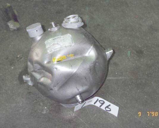
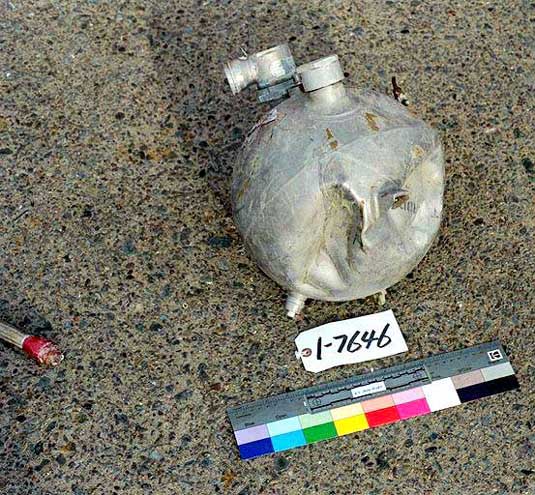
The hermetically sealed, stainless steel firex bottles are filled with the chemical agent CF3BR. Each bottle is fitted with one or two discharge head assemblies that include debris screens, explosive cartridges, and flow channels. The agent bottles are manufactured by Walter Kidde Aerospace. The cartridges are electrically fired explosive squibs that supply the energy to rupture the frangible disk in the applicable bottle outlet. The frangible disc seal also functions as a pressure relief device.
The engine fire detection system is identical in all three engines. It supplies aural and visual fire warning alerts to the flight crew of possible fire conditions in the engine compartment. The engine fire detection system receives inputs from fire zones that become too hot as a result of fire or overheat conditions. The engine compartment detection system has two separate, gas-filled, fire detector loops suppling a single FDCU. The loops are divided into three parts. Each part has two fire detector assemblies attached in parallel to a stainless steel support tube assembly. The support tube assembly (with the two fire detector assemblies attached) is routed through specific fires zones in the engine. The two loops (loop A and loop B) transmit fire warning signals to the FDCU through the tripping of a pressure switch resulting from an increase in thermal pressure in the loop caused by a rise in temperature. The FDCU has two separate channels, one for each loop. Each loop detection system can receive fire warning signals with the other loop circuit open or grounded. A discriminator circuit in the FDCU identifies the signal from the loop as a system defect or a fire.
The engine fire zones generate the following warnings in the flight compartment:
- Two red master warning lights on the glare shield
- A 750 Hz warning bell
- A red light on the applicable engine control handle (ENG 1 FIRE, ENG 2 FIRE, or ENG 3 FIRE, as applicable)
- A red light on the applicable fuel ON/OFF switch
- An applicable ENG FIRE level 3 alert on the EADM
- An applicable ENG FIRE level 3 alert on the SD
Engine 2 fire detection system
Description
The Engine 2 firex handle and FUEL switch lights are powered by the 28 V DC battery bus through CB B1-644, located at position B-20 on the overhead CB panel.
The ground wire for Firex Handle Lights 2 runs from the light to the overhead switch panel, out of the right side of the panel to the overhead disconnect switch panel (behind the avionics CB panel), then down to the FDCU in the avionics compartment. As the wire leaves the overhead switch panel (in wire runs AMK and AMJ), the wire traverses an area of known heat damage and electrical arcing and high heat. A short to ground in any of the wires, however, would cause both the Firex Handle Lights 2 and the Engine 2 FUEL switch light to come on.
A ground in the Engine 2 FUEL switch light wire run would also turn both lights on. The ground wire for the Engine 2 FUEL switch light runs through several connectors from the light on the thrust control module to the centre pedestal, and then down into the avionics compartment to the FDCU.
Examination
A 15-inch section of the Engine 2 fire detection loop A power wire B203-974-24 (Exhibit 1-1733, modified and renumbered exhibits 1-11147 and 1-12655) exhibited an area of once-molten copper.
CB B1-644 was not recovered; the CB next to it, however, CB B1-645 (Engine 3 firex handle and FUEL switch lights), located at position B-21 on the overhead CB panel, was recovered. There was no soot accumulation on the white CB indicator ring of CB B1-645.
No other wires in the wire run leaving the overhead switch panel were identified from this system.
Determination
The area of once-molten copper on the recovered 15-inch section of the Engine 2 fire detection loop A power wire B203-974-24 is typical of damage caused by an electrical arcing event. The wire was determined to be from a section of wire installed between pin *Z on connector P1-426 on the right overhead disconnect switch panel and pin 46JX on connector S3 613 in the overhead switch panel. This wire is part of the wire run that supplies 28 V DC Battery Bus power from CB B1-632 at location B-15 on the overhead CB panel to the FDCU, which is located on the forward equipment panel of the equipment rack in the avionics compartment. Because this wire is used to supply power to the FDCU (and not data from the loop detector to the FDCU, a short of this wire would not cause the FDCU to generate a fire warning signal. If the short had caused the circuit to open, loop A of the FDCU would be de-powered and only loop B would be active. With loop A de-powered, the FDCU would send a fault to the DEU, which would be displayed as "FIRE DET FAULT" level 1 alert. This level 1 alert would not likely result in flight crew action; the flight crew did not mention that this alert had occurred. If this fault occurred after the loss of DU 3, the flight crew would have been unaware of the alert. Because the FDCU and input wires to the FDCU are located in an area that did not exhibit heat damage, it was determined that an Engine 2 fire warning was not likely generated by false electrical inputs or shorts to the FDCU.
There was no soot accumulation on the white CB indicator ring of CB B1-645 to indicate that the CB had tripped prior to impact. Based on its close proximity to CB B1-644, it was determined that a fire-induced thermal trip of CB B1-644 was unlikely.
Because the entire Engine 2 FUEL switch light wire run was located outside of the fire damaged area, it was determined that a short to ground in this run was unlikely.
| Bottle Position | Bottle Recovered | Disc Ruptured | Cartridge Recovered | Cartridge Fired | Type of Discharge |
|---|---|---|---|---|---|
| Engine 1 position 101 |
Yes | No | Yes | No | |
| Engine 1 position 102 |
Yes | Cracked | No | Yes | Low energy |
| Engine 2 position 201 Engine discharge port APU discharge port |
Yes | Cracked Yes |
Yes Yes |
Yes Yes |
Low energy Over pressure |
| Engine 2 position 202 Engine discharge port APU discharge port |
Yes | No Yes |
Yes Yes |
No Yes |
Normal |
| Engine 3 position 301 |
Yes | Impacted | No | No | |
| Engine 3 position 302 |
Yes | Yes | No | Yes | Normal |
| Cargo Compt Bottle 1 Fwd Compt discharge port Aft Compt discharge port |
Yes | Unknown No |
Yes No |
No No |
|
| Cargo Compt Bottle 2 Fwd Compt discharge port Aft Compt discharge port |
Yes | Yes Unknown |
No No |
||
| APU Fire Bottle | No | Unknown | No |
Firex bottle explosive cartridges examination
Seven of the thirteen explosive cartridges were recovered from the engine, APU, and cargo firex systems. The hex flats on all of the recovered cartridges were stamped with PN OA876296. The "OA" prefix identifies the cartridges as PMA parts manufactured by Overland Aviation Services. The FAA Production Approval Listing for Parts Manufacturer Approval No. PQ3408CE, dated 5 October 1998 and applicable to Overland Aviation Services, did not list the MD-11 as an eligible model for installation of this cartridge.
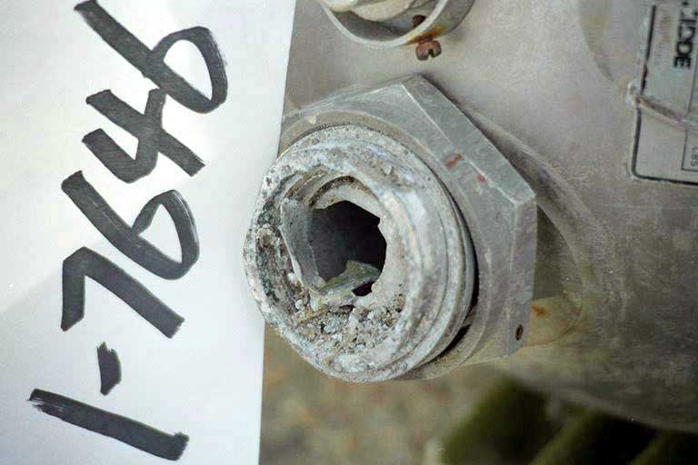
The PN OA876296 explosive cartridges were identified in Overland Aviation Services manufacturer SB 22-09-97 (issued 19 September 1997) and SB 26-20-02 (issued 22 June 1998). The SBs stated that the OA876296 cartridges, lot numbered SB11-1 or OAS1-1, had been found to release excessive energy during functioning, which could result in damage to the associated discharge heads. Two of the recovered cartridges (the Engine 2/APU outlet Exhibit 1-1306 and one cartridge for which the position could not be identified) were stamped with lot number OAS 1-1. Both cartridges had discharged with sufficient energy to rupture the cartridge housing, indicating an over-explosive condition. The remaining recovered explosive cartridges were stamped with lot number OA97DB.
Two of the engine firex container frangible discs were cracked and dented in a manner that indicated that the applicable cartridge had discharged with insufficient energy to penetrate the disc properly (Engine 1 position 102 and Engine 2 position 201). The discharged cartridge that corresponded to one of the low-energy impacts was stamped with lot number OA97DB. The cartridge associated with the other low-energy impact was not recovered.