Associated links (A98H0003)
-
Table of contents
Flight controls
Primary flight controls
Elevator actuators examination
All four elevator actuators (one per elevator segment) exhibited varying degrees of damage related to the impact and subsequent saltwater corrosion, with the right actuators exhibiting greater physical damage overall than the left actuators. Prior to disassembly, the as-recovered actuator rod extensions were measured. After disassembly, the actuators were examined for internal witness marks, which could indicate the position of the actuator at the time of impact. The measured elevator actuator piston (ram) extensions are contained in the following table:
| Actuator Assembly | Actuator Dimension (as received)Footnote 1 | Actuator Dimension (internal markings) | Comments |
|---|---|---|---|
| Left Inboard Elevator SN 0068 |
16.270 in. or 15.2° TEDFootnote 2 | 2) 18.827 in. or 6.3° TEU 3) 16.617 in. or 2.4° TED |
1) Two distinct piston positions were noted on the cylinder wall, as revealed by corrosion. |
| Left Outboard Elevator SN 0248 |
14.879 in. or 0.3° TEU | 15.052 in. or 2.0° TEU | 1) Two parallel score marks were noted on the cylinder rod from contact with the forward bearing on the secondary cylinder. 2) Piston score marks were noted on the internal wall of the secondary cylinder that align with score marks noted on cylinder rod. |
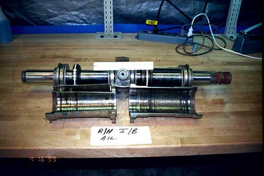
| Right Inboard Elevator SN 0015 |
18.310 in. or 1.6° TEU | 18.490 in. or 3.2° TEU | 1) Cylinder rod end bent with marks on cylinder rod from contact with forward bearing on secondary cylinder. 2) Piston marks on the internal wall of both primary and secondary cylinders that align with score marks noted on cylinder rod. |
| Right Outboard Elevator SN 0031 |
14.280 in. or 5.3° TED | 15.170 in. or 3.1° TEU | 1) Two parallel score marks were noted on the cylinder rod from contact with the forward bearing on the secondary cylinder. 2) Piston score marks were noted on the internal wall of the secondary cylinder that align with score marks noted on cylinder rod. |


No pre-existing faults were identified within any of the actuators or manifold assemblies.
Aileron actuators examination
All four aileron actuators (one per aileron) exhibited varying degrees of damage related to the impact and subsequent saltwater corrosion. Prior to disassembly, the as-recovered actuator rod extensions were measured. After disassembly, the actuators were examined for internal witness marks, which could indicate the position of the actuator at the time of impact. The measured aileron actuator piston (ram) extensions are contained in the following table:
| Actuator Assembly | Actuator Dimension (as received) |
Actuator Dimension (internal markings) | Comments |
|---|---|---|---|
| Left Outboard Aileron SN 0058 |
14.300 in. or 18.1° TED | 12.775 in. or 1.9° TED | 1) Piston score marks on forward and aft cylinders in captured position. 2) Piston score marks on forward and aft cylinders in secondary position. |
| Right Outboard Aileron SN 0046 |
12.030 in. or 6.1° TED | 12.958 in. or 3.8° TED | 1) Piston score marks on forward and aft cylinders in captured position. 2) Impact blow to forward cylinder, which perforated cylinder and damaged piston head seal groove in secondary position. Piston score marks on forward cylinder in secondary position. |
| Left Inboard Aileron SN unknown |
19.150 in. or 12.5° TEU | 20.630 in. or 0.2° TEU | 1) Piston score marks on forward and aft cylinders in captured position. 2) Parallel score marks were noted on the cylinder rod from contact with the forward bearing on the forward cylinder. |
| Right Inboard Aileron SN 747 |
19.246 in. or 11.7° TEU | None | 1) Piston score marks on forward and aft cylinders in captured position. |


No pre-existing faults were identified within any of the actuators or manifold assemblies.
Outboard aileron lockout
The outboard ailerons are low-speed ailerons and are automatically locked in the neutral position in high-speed configurations. With the extension of the slats or landing gear, or with a flap extension of 10 degrees or greater, the outboard ailerons become fully active. As the flaps were determined to have been extended to 15 degrees before impact, the outboard ailerons would have been fully active.
Rudder actuators examination
Both rudder actuators (one per rudder segment) exhibited varying degrees of damage related to the impact and subsequent saltwater corrosion, with the lower rudder actuator exhibiting the greater overall damage. Prior to disassembly, the as-recovered actuator rod extensions were measured. After disassembly, the actuators were examined for internal witness marks, which could indicate a position of the actuator at the time of impact. The measured rudder actuator piston (ram) extensions are contained in the following table:
| Actuator Assembly | Actuator Dimension (as received) |
Actuator Dimension (internal markings) | Comments |
|---|---|---|---|
| Upper Rudder SN 549 |
14.956 in. or 0.3° TELFootnote 3 | 15.311 in. or 2.8° TER | 1) Two sets of piston marks were noted on the cylinder wall. One in the captured position, and one 0.355 in. in the extend direction. |
| Lower Rudder SN unknown |
14.609 in. or 3.3° TEL | 14.609 in. or 3.3° TEL | 1) Cylinder rod bent with marks on cylinder rod from contact with forward bearing on cylinder. 2) Piston marks on the internal wall of cylinder that align with marks noted on cylinder rod. |


No pre-existing faults were identified with either actuator or manifold assemblies.
Secondary flight controls
Flap/Slats system
Description
Wing flap system
There are two flap segments on each wing, one inboard and one outboard, each consisting of a flap and a vane. When the flaps are lowered, the vane increases the effectiveness of the flap system. Each flap segment is driven by two actuating cylinders, which are powered by two independent hydraulic systems.
Normal flap/slat operation is controlled by a single lever on the right side of the cockpit centre pedestal. The flap/slat control lever can be selected to five detent positions. (A 1.75 degrees "blue dot" detent is provided for rigging purposes only–the blue dot being a plug put in the detent position after rigging is accomplished.) The first detent position does not move the flaps, but extends all 16 (8 per side) leading edge slats. Normal slat extension is limited to speeds below 280 knots; it is generally selected to reduce speed during the initial landing approach or when the manoeuvring speed is less than approximately 250 knots. A take-off flap selector wheel provides a pre-selected detent for any flap setting between 10 degrees and 25 degrees. This second DIAL-A-FLAP setting is normally pre-selected to 15 degrees by the crew during their climb check procedures, and is used to slow the aircraft down, during initial approach, to the Vmin speed (for the current aircraft configuration) plus 20 knots. Depending on the weight and the C of G, this speed may be around 180 knots. The third detent position is the 28 degrees flap setting. This detent is generally used to slow the aircraft to an approach speed of the Vmin speed (for the current aircraft configuration) plus 5 knots (approximately 160 knots). The GEAR DOWN selection would normally be made after the selection of 28 degrees flap. The fourth detent position is the 35 degrees flap setting. This detent is normally used to slow the aircraft to the final FMS approach speed, to establish a stabilized approach before or upon reaching 1 000 feet agl. A switch provides a signal for the gear warning horn to activate if the flaps are in this position and the gear is not down. The fifth detent position is the 50 degrees full flap position. Normal landing flap is 35 degrees, while 50 degrees flap is used for high-performance landings.
Slats system
The MD-11 is equipped with eight slat segments on each wing–two inboard and six outboard of each engine–to provide lift augmentation at the lower speeds. The slats are electrically controlled and hydraulically actuated and have two positions: retracted or extended. Movement of the flap/slat control handle operates four switches in the flap/slat module, which provide signals to the inboard and outboard slat control valves for slat extension and retraction. The slat control valves, when activated, direct hydraulic pressure from hydraulic systems 1 and 3 to operate the two inboard and the four outboard hydraulic slat actuators. The slats are equipped with an overspeed protection system, which prevents the operation of the slats above 280 knots. The slat overspeed protection system is inhibited by a flap extension of 10 degrees or more. The slats are also equipped with an auto-extend system that extends the outboard slats at the onset of the stall warning system. If the stall is averted, the slats will automatically retract. In the event of a slat disagree alert or a loss of pressure from hydraulic systems 1 and 3, the slats are equipped with a SLAT STOW button. Operation of the SLAT STOW button enables the crew to lock the slats in the retracted position while operating the flaps.
The slat control valves receive their electrical power from the right emergency 28 V DC bus, through CB B1-30, at position E27 on the overhead CB panel (slat control power A); and the 28 V DC Bus 2, through CB B1-31, at position F2 on the lower avionics CB panel (slat control power B). The slat control valves will operate with one of the two power supplies inoperative.
Examination
Flap actuators
All eight flap actuators exhibited varying degrees of damage related to the impact and subsequent saltwater corrosion. All of the actuator rod extensions were measured and three of the eight actuators were disassembled, cross-sectioned and examined for internal markings, which could indicate the position of the actuator at the time of impact. The resulting actuator extensions are contained in the following table:
| Actuator Assembly | Actuator Dimension (as received) | Actuator Dimension (internal markings) | Comments |
|---|---|---|---|
| Left Outboard Flap Outboard Actuator | 25.9 in. or 12.0° FEFootnote 4 | ||
| Left Outboard Flap Inboard Actuator | 30.9 in. or 35.0° FE | 1) Actuator rod end failed in tensile overload, which may have moved the actuator upon impact. |
|
| Left Inboard Flap Outboard Actuator | 34.3 in. or 38.0° FE | See noteFootnote 5 | 1) Actuator rod moves freely within cylinder, captured position uncertain. |
| Left Inboard Flap Inboard Actuator | 27.8 in. or 11.0° FE | 29.237 in. or 16.8° FEFootnote 6 | 1) Piston scores marks on cylinders in captured position. 2) Score mark on cylinder rod from contact with the forward gland nut on cylinder.Footnote 7 |
| Right Inboard Flap Inboard Actuator | 28.3 in. or 13.0° FE | ||
| Right Inboard Flap Outboard Actuator | 27.9 in. or 11.0° FE | See noteFootnote 8 | |
| Right Outboard Flap Inboard Actuator | 25.9 in. or 12.0° FE | ||
| Right Outboard Flap Outboard Actuator | 26.3 in. or 13.0° FE |


Flap/Slat control handle
An examination of the flap/slat control handle arrangement revealed a distinct witness mark on the flap/slat detent track made by the flap/slat lever (or handle) being forced and bent approximately 60 degrees to the left upon impact.

The position of the lever in relation to the impact markings placed the flap/slat control handle in the DIAL-A-FLAP range setting. The sector gear, which connects the take-off flap selector wheel to the DIAL-A-FLAP detent, consists of 17 gear teeth. Two of the teeth (the sixth and seventh from the lower flap limit), showed distinct gouging, caused when the sector gear and its pinion gear were forced together upon impact.

Assuming that the pinion gear and sector gear were mated such that the use of all 17 teeth would represent the full range of movement between 10 degrees and 25 degrees, then the movement of one tooth would change the DIAL-A-FLAP setting by 0.88 degrees. If that were the case, then the damage at teeth 6 and 7 would represent a DIAL-A-FLAP setting of between 15 degrees and 16 degrees, which is the standard position pre-selected by the crew during their climb check.
Inboard slat control valve
The inboard slat control valve was recovered and its position identified by a Swissair identification tag (IDN 473306, AS 0013). The electric motor, used to linearly move the internal hydraulic valve assembly, was broken and missing. The manual select lever/indicator was in the slats-retract position. The lever/indicator was undamaged and displayed no signs of being driven into the slats-retract position. The valve body assembly contained seven of its eight inlet/outlet fittings and check valve assemblies.

Outboard Slat Control Valve
The outboard slat control valve was recovered and its installed position identified by a Swissair identification tag (IDN 473306, ASN 0017). The electric motor was still attached; however, it was bent to one side, and three of the four mounting bolts had pulled free from the valve body. The manual select lever/indicator was captured in a position three quarters of the way toward the slats-extended position. The lever/indicator was undamaged; however, the position of the lever may have been influenced by the damage to the electric motor.

Inboard slat actuators
One of the two inboard actuators was identified by the MD-11 IPC as PN 70739-1 (BRG0010-5519). The SN is unknown, as the actuator identification tag was missing. The actuator overall extension, from the centre of the body mounting holes to the centre of the actuator clevis hole, was 17.6 inches; the actuator chrome was extended 1.75 inches These extensions are consistent with the slat actuator having been in the fully retracted position. (The inboard actuators are retracted to retract the slats.)

The second inboard slat actuator was identified, by tag, as PN 70739-1 (BRG0010-5519), SN 50. The actuator was removed from a piece of the slat drive mechanism structure. The actuator overall extension, from the centre of the body mounting holes to the centre of the actuator clevis hole, was 17.6 inches; the actuator chrome was extended 1.75 inches These extensions are consistent with the slat actuator having been in the fully retracted position.

Outboard slat actuators
One of the two left outboard actuators was identified by the MD-11 IPC as PN 1538200-1 (BRG0012-5505). The actuator tag was missing. Three outboard slat actuator tags (SN 0131, 0092, and 0097) were found loose among the wreckage, but could not be matched with their respective actuators. The actuator cylinder was fully extended and bent at the end of the actuator body. The actuator overall extension, from the centre of the body mounting holes to the centre of the actuator clevis hole, was 24.4 inches; the actuator chrome was extended 7 inches The outboard slat actuators move in an opposite direction to the inboard slat actuators in that they are extended to retract the slats. The actuator was determined to be in the fully extended, or slats-retracted, position.

The second left outboard actuator was identified by the MD-11 IPC as PN 1538200-1 (BRG0012-5505). The actuator tag was missing. The actuator cylinder was bent at the actuator housing and had broken off. The internal measurement of the remaining actuator cylinder was 4 inches to the actuator housing seal, which is consistent with a fully extended cylinder. The actuator cylinder was recovered and the chrome measured at 7 inches to the bend in the actuator. The actuator was determined to have been in the fully extended, or slats retracted, position.
One of the two right outboard actuators was identified by the MD-11 IPC as PN 1538200-1 (BRG0012-5505). The actuator tag was missing. The actuator cylinder was broken off at the end of the actuator housing. The internal measurement of the remaining actuator cylinder was 4 inches to the actuator housing seal, which is consistent with a fully extended cylinder. The actuator was determined to have been in the fully extended, or slats retracted, position.
The other right outboard actuator was identified by the MD-11 IPC as PN 1538200-1 (BRG0012-5505). The actuator tag was missing. The actuator cylinder was broken off at the end of the actuator housing. The internal measurement of the remaining actuator cylinder was 4 inches to the actuator housing seal, which is consistent with a fully extended cylinder. The actuator was determined to have been in the fully extended, or slats retracted, position.
Slat tracks
The slat tracks were recovered and examined. Of interest was a series of markings noted on the upper roller surface on several of the slat tracks. The marks or scratches were made from contact with the upper rear roller bearing as it failed on impact. The direction of the scratches indicated that the failure of the rear bearing occurred while the slats were in the retracted position and progressed forward as the slats were torn from the wing.
Slat disagree alert
A slats disagree alert is a recorded FDR parameter. This parameter was not recorded prior to the loss of the FDR. The FDR recorded that the four slats L2/L4 and R2/R4 went from retract to transit. Between 0125:06 and 0125:14 (while the DFDAU was outputting frozen DEU-1 data) the PSEU B sensors changed from "target near" to "target far." This resulted in the DEU output to the DFDAU changing from "retract" to "transit." At 0125:15, the transit state was recorded from DEU-3. This change of state has two possible causes. Either the slats are actually transitioning, or there is a loss of power to the B sensors. Investigation concluded that the slats were not moving. The airspeed of 320 knots exceeded the slat overspeed protection threshold of 284 knots, which inhibits slat extension. The crew never discussed deploying the slats and there was no sound signature heard on the CVRthat would normally be associated with the slat/flap lever or slats deploying. Furthermore, the slats were found to have been retracted at the time of impact. Therefore, it was concluded that B sensor power was lost.
Power for the B sensors is provided by the 28 V DC Bus 1 through CB "Slat Pos Sys 2" on the upper avionics CB panel at position E-09. The loss of power to the "Slat Pos Sys 2" CB would not have any effect on the cockpit displays. At the time the recorders lost power, it is possible that DUs 1, 3, 4, 5, and 6 were blank. If there was an actual slats disagree event after the flight recorders stopped at 0125:41, then the crew may not have seen the alert and would not have pushed the SLAT STOW button.
Determination
An examination of the flap/slat control handle and the eight flap actuators indicated that the flaps had been lowered prior to impact, probably to the 15 degrees detent. This position is consistent with the DIAL-A-FLAP wheel being pre-selected by the crew during their climb check procedures.
The slats are normally extended automatically with flap extension; however, all six slat actuators were captured in the retracted position at the time of impact. Because the flaps were found extended beyond the 10 degrees position, the slat overspeed protection system would have been inhibited and would not have prevented the slats from extending. The slat extend function can be overridden by the use of a SLAT STOW button, but it is unlikely that this was used. The SLAT STOW button would normally be used only with a slat disagree alert, or after the loss of hydraulic systems 1 and 3. If a slat disagree event occurred, it is unlikely that the crew would have been aware of it. A loss of hydraulic systems 1 and 3 is unlikely, as engines 1 and 3 were running at the time of impact.
As the slat control valve CBs (on the overhead and lower avionics CB panels) are near the known fire damage and electrical arcing events, it is likely that the failure of the slats to extend was a result either of a loss of (or interruption in) the electrical wiring to the slat control valves, or a tripping of the control CBs caused by heat from the fire.
Spoiler system
Examination and determination
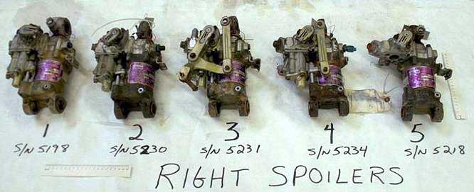
Spoiler actuators
All 10 spoiler actuators (5 per wing) exhibited varying degrees of damage related to the impact and subsequent saltwater corrosion. Prior to disassembly, the as-recovered actuator rod extensions were measured. After disassembly, the actuators were examined for internal witness marks, which could indicate a position of the actuator at the time of impact. The measured spoiler actuator piston (ram) extensions are contained in the following table:
| Actuator Assembly Spoiler | Actuator Dimension (as received)Footnote 9 | Actuator Dimension (internal markings) | Comments |
|---|---|---|---|
| Left No. 5, SN 5220 | 9.1015 in. (retracted) | None | 1) Input lever damaged |
| Left No. 4, SN 5211 | 9.1025 in. (retracted) | None | |
| Left No. 3, SN 1340 | 9.0985 in. (retracted) | None | |
| Left No. 2, SN 5217 | 9.1920 in. 1.6° upFootnote 10 | None | 1) Rod end damaged; bearing pushed out. |
| Left No. 1, SN 5291 | 9.270 in. 3.0° up | None | 1) Input lever slightly damaged/bent. |
| Right No. 1, SN 5198 | 9.124 in. 0.3° up | None | 1) Rod end and bearing damaged. |
| Right No. 2, SN 5230 | 9.1110 in. (retracted) | None | |
| Right No. 3, SN 5231 | 9.490 in. 7.0° up | None | |
| Right No. 4, SN 5234 | 9.1670 in. 1.1° up | None | |
| Right No. 5, SN 5218 | 9.1135 in. 0.1° up | None | 1) Input linkage missing. |

No pre-existing faults were identified within any of the actuators or manifold assemblies.
Spoiler handle track
The spoiler handle track is mounted in the cockpit centre pedestal to the left of the throttle quadrant. The track has four detent positions: RETRACT, 1/3, 2/3, and FULL (speed brake positions). The single-lever spoiler handle is equipped with a sliding bar arrangement that engages with the applicable slot in the spoiler track, depending on the setting desired. During examination of the spoiler handle track, an indentation was found on the rear face of the RETRACT slot position, indicating that the spoiler handle was most likely in that position at the time of impact.


Horizontal stabilizer trim system
Description
The MD-11 is equipped with an adjustable horizontal stabilizer to provide longitudinal trim of the aircraft. The stabilizer is moved by two jack screw actuators, which are connected to a common gearbox through drive chains. The gearbox is operated by two independent, two-speed hydraulic trim motors, which are powered by aircraft hydraulic systems 1 and 3. The hydraulic stabilizer control valves direct hydraulic fluid to the hydraulic trim motors, which turn the stabilizer gearbox and then operate the actuators via chains. Backup hydraulic power to the hydraulic motors is provided by Hydraulic System 2, through the 2-1 non-reversible motor pump. The horizontal stabilizer can be controlled in the following four modes of operation:
- Automatic pitch trim via autopilot
- Automatic pitch trim via LSAS
- Manual, electrically commanded pitch trim via control wheel trim switches
- Manual, mechanically commanded pitch trim via longitudinal trim ("suitcase") handles
Automatic pitch trim via autopilot
When the autopilot is engaged, the stabilizer position is automatically controlled by the FCC to off load steady-state elevator commands greater than 1.3 degrees.
Automatic pitch trim via LSAS
During manual flight operations, the LSAS will command the elevators to maintain the airplane's pitch attitude and, if required, will gradually off load the elevator input by moving the horizontal stabilizer through an automatic pitch trim function. This LSAS automatic pitch trim function is inhibited if any of the following conditions apply: the aircraft bank angle exceeds 5 degrees; the pitch force applied to the control column exceeds 2 lb; or the crew is manually trimming the stabilizer with either the control wheel trim switches or the longitudinal trim handles. The LSAS system has four independent channels, which operate through the two FCCs. The LSAS automatic trim function will remain operative as long as one FCC channel is available.
Manual, electrically commanded pitch trim via control wheel trim switches
Manual, electrically commanded actuation of both horizontal stabilizer trim motors is available through use of the electric trim switches located on both crew control wheels, and will move the stabilizer in the commanded direction. Electrical power for the trim switches is supplied by the 28 V DC Bus 2 through CB B1-507, located at position F3 on the lower avionics CB panel.
Manual, mechanically commanded pitch trim via longitudinal Trim ("suitcase") handles
Manual, mechanically commanded pitch trim, through the use of the longitudinal trim handles (which resemble suitcase handles), is provided by cables and pulleys to the hydraulic stabilizer control. This method is entirely mechanical and does not require any electrical power. The manual input to the hydraulic control valves overrides electrical inputs to the valve.
Horizontal Stabilizer Jack Screw Rigging Dimensions
The MD-11 horizontal stabilizer rigging instructions are contained in the MD-11 Maintenance Manual, Section 27-40-00-5. The rigging is controlled by adjusting the stabilizer jack screw actuators and indicating system to a neutral position and then ensuring that the actuators meet their full travel-range dimension checks. The actuator dimension is determined by taking a measurement of the actuator length between the actuator's upper and lower stop surfaces.
The rigging dimensions as shown in the MD-11 Maintenance Manual, Section 27-40-00-5, are as follows:
| Aircraft Nose Up | Configuration page, 15.5° to 17.0° ANU | 0.61 to 1.51 in. Actuator extension |
|---|---|---|
| Neutral | Configuration page, 0° ± 1.0° | 30.68 to 30.83 in. Actuator extension |
| Aircraft Nose Down | Configuration page, 0.9° to 2.2° AND | 33.17 to 34.06 in. Actuator extension |
Examination
Horizontal stabilizer jack screw
The left horizontal stabilizer jack screw actuator was recovered as a single unit. The actuator was identified through the MD-11 IPC as PN AJH 7349-503. The upper clevis end was broken away and found attached, in place, to a piece of the horizontal stabilizer box structure. The actuator screw nut and portions of the drum assembly and attachment structure were still attached to the actuator. The actuator upper and lower stop collars were intact and did not show signs of contact. The actuator and clevis end were mated and the actuator extension was measured at 30.69 inches, or just within the minimum neutral extension limit. The screw nut was free to rotate.

The right horizontal stabilizer jack screw actuator was recovered as a single unit. A data plate on the drum assembly identified the actuator as having been manufactured by Peacock Engineering Co., PN AJH 7349-505, SN DCA-449. The upper clevis end was broken away and found attached, in place, to a piece of the horizontal stabilizer box structure. The actuator screw nut and portions of the drum assembly were still attached to the actuator. The actuator (by design) was not equipped with upper or lower stop collars. The actuator and clevis end were mated, and the actuator extension was 30.94 inches, or just outside the maximum neutral extension limit. The screw nut was not free to rotate.

Determination
Horizontal stabilizer trim system
Both of the horizontal stabilizer jack screw actuators were recovered at or near the neutral position. Some movement or rotation of the actuators screw nuts may have occurred upon impact, as shown by the slight difference in the actuator measurements and the sheared pinion pin in the stabilizer gear box drive chain unit. However, this movement, in relation to the overall length of the actuator, is considered to have been minimal, and would have had little effect on the recovered positions of the actuators (possibly given an error of −1 degree).
The last recorded DFDR horizontal stabilizer positions occurred at an altitude of 10 386 feet. The last recorded position for the left stabilizer LVDT (stab 1) was 1.1 degrees ANU at a time of 0125:07. The last recorded position for the right stabilizer LVDT (stab 2) was 1.0 degree ANU at a time of 0125:38. A review of the DFDR stabilizer data did not show any anomalies. The manufacturer calculated that, with the flaps set at 16 degrees and the slats retracted, possible horizontal stabilizer settings during an approach phase of flight could be approximately 4 degrees ANU at 200 knots or 3 degrees ANU at 300 knots.
The difference in the calculated stabilizer position and recovered position of the horizontal stabilizer jack screw actuators is not considered significant, and may be explained by one of the following possibilities:
- The recovered position of the horizontal stabilizer was in the correct position for the aircraft's configuration at the time of impact.
- The crew added elevator input just before impact, and the automatic trim system did not have sufficient time to trim the horizontal stabilizer before impact.
- The horizontal stabilizer was not trimmed, or was trimmed only slightly, during the descent below 10 000 feet, owing to a loss of electrical power to the automatic and manual electric pitch trim modes (the manual mechanical mode would still, however, have been available).
- The stabilizer actuators moved at or after impact and did not reflect the actual position of the actuators at the time of impact.
- The aircraft was not in controlled flight.