Associated links (A98H0003)
Flight recorders
Flight data recorder
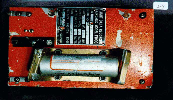
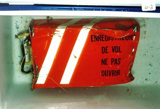
The aircraft's FDR was recovered by divers on 6 September 1998 in approximately 50 m of water. It was escorted to the TSB Engineering facility in Ottawa for analysis. The FDR was transported in distilled water to minimize oxidation from exposure to salt water.
The FDR was an L3 Communications (formerly Loral/Fairchild) Model F1000, SN 00898, which recorded approximately 250 parameters in solid state memory. The F1000, which uses data compression techniques to store data, contained approximately 70 hours of continuous flight data.
The ULB for the FDR was intact and attached to the crash-protected memory module. The brackets that held the beacon were damaged substantially, but still held the beacon in place.
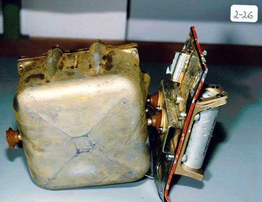
The recorder was rinsed in a fresh water bath and then disassembled. The crash-protected memory module was kept submerged in water as much as possible, to minimize the effects of oxidation. The internal crash module was removed from the outer dust cover and internal housing. The internal crash module was in good condition, with no signs of impact damage.
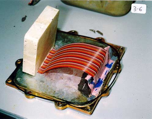
The internal solid state memory devices are encapsulated in a foam material for this model of FDR. The foam-encased memory module was relatively dry and undamaged.
As a precaution, a new ribbon cable connector was spliced onto the memory module and the module was placed in one of the TSB's F1000 bench units for downloading. Power was applied to the memory module and the data was successfully recovered and copied into the TSB's computer systems.
The TSB's Recovery Analysis and Presentation System was used to recover the entire memory contents, which included the accident flight and six previous flights. The recording was of good quality and contained no synchronization problems or data losses (prior to the end of the recording). The final seconds of recorded data, including a final partial sub-frame of data (a partial second), were recovered with the assistance of the recorder manufacturer. All of the data was converted into engineering units using the documentation provided by Swissair, SR Technics, Boeing, and Teledyne (the manufacturer of the flight data acquisition unit). The original parameter documentation listed two discretes that were not recorded on this aircraft:
- Lavatory Smoke (not recorded on the FDR)
- Cabin (Cargo) Smoke (only installed in cargo-configured aircraft)
All recorded parameters were reviewed for the occurrence flight and the six previous flights. Flight recorder data for the entire flight that is considered relevant to this occurrence is presented in graphical format. (See Appendix A – Flight Profile: Selected Events in the report.) This covers the one hour and eight minutes from the take-off at JFK to the point when the recorder stopped.
The time reference for the FDR data is in UTC, which is synchronized to the radar time unless otherwise noted. Heading data is depicted in degrees with respect to magnetic north. Recorded pressure altitude is presented in feet and refers to altitude asl, assuming standard sea level pressure of 29.92 in. Hg. Derived indicated altitude is presented in feet above msl, corrected for pressure, based on the altimeter setting used for the specified segment of flight. The DU configuration parameter was calibrated with a range of 0 to 63 units, consisting of 64 possible configurations as indicated by a DU configuration matrix. For example, a recorded value of 0 indicates a typical configuration corresponding to all DUs (1 to 6) turned ON, as follows: DU1 = Left PFD, DU2 = Left ND, DU3 = EAD, DU4 = SD, DU5 = Right ND, and DU6 = Right PFD.
FDR anomalies
Progressive anomalies were evident with some of the FDR parameters in the last minute of the recording, following level-off at approximately 10 000 feet. Some of the anomalies were determined to be fault codes, corresponding to either NCD or NDU (no DITS update). The parameters that recorded fault codes toggled between 0 and a specified value corresponding to the fault code. For 12-bit data, the decimal equivalents of the recorded binary fault codes were 1536 for NCD and 2304 for NDU.
In the case of the NCD fault, it is the LRU that performs signal monitoring and generates the fault code. The NDU fault code is generated by the FDAU when it detects a loss of bus input.
Cockpit voice recorder
The aircraft's CVR was recovered by divers on 11 September 1998 in approximately 50 m of water. It was escorted to the TSB Engineering facility in Ottawa for analysis. The CVR was transported in distilled water to minimize oxidation from the exposure to salt water.
The CVR was an L3 Communications (formerly Loral/Fairchild) Model 93-A100-81, SN 25413, manufactured in September 1982. The 1/4 inch Mylar® tape has a nominal recording time of 30 minutes.
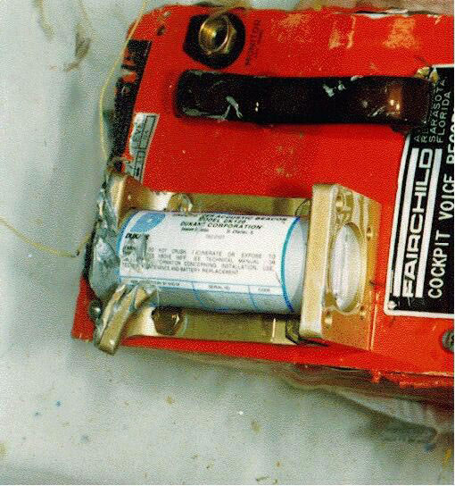
The ULB for the CVR was intact and attached to the crash-protected memory module. The brackets containing the beacon were damaged substantially, but were still holding the beacon in place.
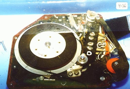
The tape was intact, with no indication of tape damage. The tape was cleaned and dried with alcohol and placed on a reel for playback. A copy tape was made of the entire 32 minute, 27 second, recording. Several one- and two-channel digital audio files were made from the original four-channel recording to provide suitable combinations for analysis.
The CVR contained four separate tracks, which recorded the output of the two pilot's audio panels (one channel for each pilot), the observer's audio panel (where cabin interphone and PA had been selected) and the CAM. The TSB established a CVR Audition Group to transcribe the recording. Through voice recognition, breathing patterns while wearing oxygen masks, and crew activity, most voice communications could be attributed to specific crew members.
The quality of the recording was fair. A few areas of interest were masked by VHF transmissions involving other aircraft, which emanated from an overhead speaker within the cockpit, particularly at the beginning of the recording, when VHF 1 or VHF 2 was selected by the captain on his communications radio panel. There was less VHF masking toward the end of the recording. Prior to their use of the oxygen masks, the pilots were not using intercom "boom" microphones to communicate to each other, so it was necessary to rely on the CAM channel to discern internal communications. Some communications were not discernable on the CAM channel owing to normal ambient noise and masking by external radio communications from the overhead cockpit speaker. The oxygen mask microphones were "hot" (always recording) to the CVR, but the crew had to activate a rocker switch in one direction to communicate internally and in the other direction to transmit externally over the VHF radio.
Recorded cabin and cockpit conversation was mostly in Swiss-German, with some French and English spoken. The non-English words transcribed were documented in English, as translated by the Audition Group. Some of the translations from Swiss-German were affected by the context in which the word(s) were spoken. The CVR recording and transcript are privileged under the Canadian Transportation Accident Investigation and Safety Board Act.
All CVR tracks were transcribed. There were a few unintelligible words and phrases that could not be deciphered or transcribed. Some of the radio traffic not related to the flight was not transcribed; however, all radio calls to and from SR 111 were transcribed. Only the captain's channel (P1) and the CAM channel contained VHF 2 radio traffic (Oceanic clearance frequency) and these were all to or from other aircraft. VHF 1 was used as the primary ATS radio.
CVR audition group
Because cockpit voice recordings are protected, only a few people were given access to the recording for the purposes of developing an accurate transcript and developing a factual summary of events. The US and Swiss accredited representatives to the investigation were asked to each nominate two members to the CVR Audition Group. Members were accepted by the TSB based on their expertise in one or more of the following areas:
- MD-11 aircraft or flight systems engineering
- MD-11 aircraft operations
- CVR expertise
- Familiarity with the voices of the flight crew members
- Fluency in English and Swiss-German
Time synchronization of FDR/CVR/ATS/Radar/FADEC
During the initial examination of the FDR, prior to recovery of the CVR, the FDR arbitrary time reference was converted to UTC by matching pressure altitude from the Halifax radar data–which contained UTC time stamp information–with pressure altitude recorded on the FDR. The VHF keying data from the FDR was then compared with the ATS communications. The information on the FDR and ATS tapes was in agreement regarding the timing of radio communications. However, the specific UTC times recorded on the ATS tape differed from the UTC time obtained from radar data; ATS time was approximately 2.9 seconds ahead of radar time. UTC information on the radar was considered to be more accurate than information recorded on the ATS tape owing to the automatic updating of the UTC time stamp of the radar data. Therefore, radar UTC was used in the flight recorder analysis.
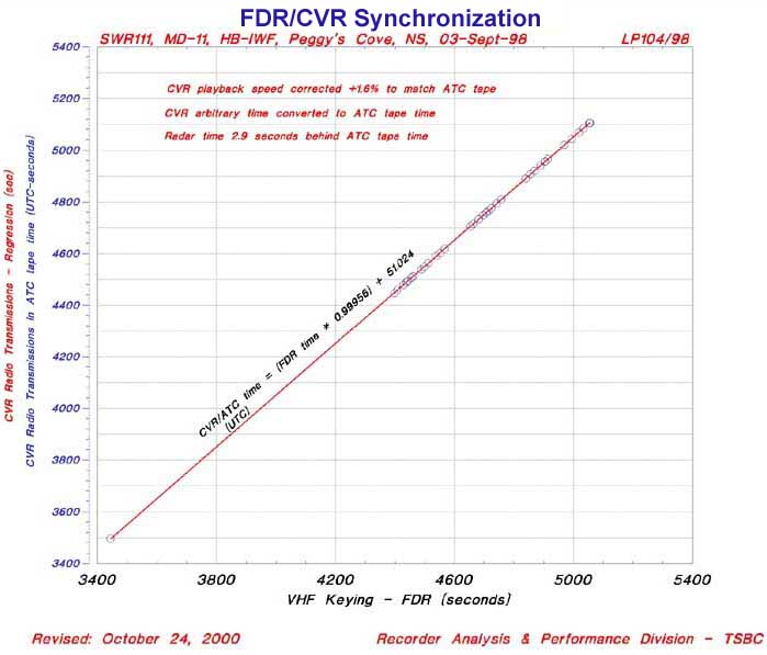
When the CVR was subsequently recovered, the tape was played back on an open reel-to-reel playback deck at the normal playback speed of 1 7/8 inches per second and simultaneously digitized. Upon playback, it was found that the CVR recording was not playing at the correct speed, but was approximately 1.6% too slow, compared with the identical radio communications on the ATS tape. This was likely a result of a slight difference in playback speed when applying the nominal 400 Hz AC power to the TSB's playback hardware. Based on this information, the CVR recording was re-digitized to provide for playback at the correct speed. As with the ATS tape, VHF keying information from the FDR was then used to synchronize the FDR with the CVR recording.
Quick access recorder
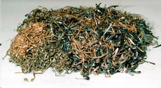
The QAR installed on SR 111 recorded six times the number of data parameters as the mandatory FDR. Consequently, there were many additional parameters of interest to the investigation. Many fragments of magnetic tape were recovered from the wreckage. Most of these fragments were from personal audio cassettes and video cassettes.
Twenty-one segments of tape, identified by tape dimensions, were considered likely to have been from the QAR installed on SR 111. These fragments were between 1 and 117 inches (10 feet) long. The QAR used by Swissair is the Penny & Giles magnetic tape cartridge (digital ADAS recorder, or DAR). The bits are encoded and recorded on the tape using the MFM method. This is a different method than that used on FDR tapes. Some FDRs use Harvard Bi-Phase signals (Harvard Bi-Phase signals are used as a coding method to represent binary data as a waveform), where the signal transition widths are 1 and 2 times the clock period. With MFM, there are three widths: 1, 1.5, and 2 times the clock period. The 2 times transition width is only 33% wider than the 1.5 times transition width. With Harvard Bi-Phase, the 2 times transition width is 100% larger than the 1 times transition width. This means it is more difficult to distinguish the bit cell widths for the MFM signal. Also, when recovering the bit information from these signals, errors in detection can propagate, since decisions on what the bits are, depend on the values determined for previous bits. For example, a 1 times width can mean a binary 1 if the previous bit was a binary 1, or it can mean a binary 0 if the previous bit was a binary 0.
The QAR records 384 twelve-bit "words" every second. This compares with normal tape-based FDRs, which record up to 64 twelve-bit words every second. The 384 words make up what is called a subframe; there are four subframes per frame, similar to an FDR. The QAR assembles two frames (8 seconds) as a block and surrounds this data with block status information, cyclic redundancy code checksum (error detection), and pre-amble and post-amble. The entire block is written to the tape and spaced apart with a dead signal, called the inter-record gap, to separate the records. Both the pre-amble and post-amble are 8 bytes. The block status is 4 bytes, while the checksum is 2 bytes. The data itself is 4 608 bytes, for a total of 4 630 bytes. There are normally four tracks of information. Because the tape had been recently changed, and because new tapes are bulk-erased, the data would expected to be found on only one track. A QAR tape with valid data was secured from Swissair to do tests with a "known quantity."
The tape fragments were spliced onto one reel, with the recording sides wound on the inside of the tape. The tape was played back and digitized using a PC sound card, sampling at 48 kHz. The signal waveform was analyzed and data was found on 8 of the 21 fragments. The data was found on tracks 2 and 3. This was likely just one track, since there was no way of knowing the orientation of the tape when splicing. It was considered necessary to "reverse" one of the two tracks, in order to digitize in the correct direction. The fragments containing data ranged from 3 to 27 inches in length (which represents about 15 seconds of data).
The manufacturer's equipment was tested to explore what capability was available to recover data from a known test tape and then from the occurrence aircraft tape. The method used required putting the tape in a QAR cartridge and then playing back the tape using the QAR hardware playback equipment. The manufacturer's equipment was able to retrieve data from the test tape but not from the accident tape using this method. Subsequent to this, an effort was made to recover data using software decoding methods available within the TSB's Recovery Analysis and Presentation System. A new algorithm was required for the MFM signal, since this format had not been dealt with before. Unfortunately, even for segments where the signal was somewhat recognizable, bit "timing" problems, as a result of possible stretching of the QAR tape, and problems with the amplitude of the waveform, made it possible to only decode occasional, even shorter streams of bits.
The number of bits that could be contiguously decoded was insufficient to establish where the data was located with any data frame and was, therefore, impossible to transcribe into meaningful engineering units. Other segments contained an undecodable signal because of the severe distortion as a result of the crash trauma.
The test tape signal was decoded without problem using the TSB's software.
Circuit breaker study
A number of clicks were audible on the CVR (and documented in the CVR transcript). Most of these clicks were considered normal cockpit sounds; however, a few were studied further, in an effort to determine whether the sound was a CB trip, given that the investigation had focused on the possibility of an electrical problem as the possible source of the fire. Factors that may have influenced the acoustic signature include the following:
- The size and type of breaker;
- The location on the panel, and on which panel;
- A trip by ambient heat;
- An electrical overload trip;
- The background acoustic environment at the time of the trip;
- The recording system (actual CVR versus cassette recorder);
- The amplitude of the trip; and
- The location of crew members obstructing the source.
SR Technics conducted a series of ground and flight tests to develop a basis of sound for known CB trips under different conditions and for different sized breakers and locations on the various panels. The test data was created by the following three methods: pulling the CB by hand; tripping the breaker on the ground by overloading the CB; and pulling the circuit breaker with a string. Breakers were pulled with a string because it was felt that pulling with the human hand would likely dampen the acoustic response. It was not possible, on an in-service aircraft, to simulate a CB trip caused by high ambient temperature.
In addition to the theoretical tests, a click was evident on the CVR in the second before the autopilot disconnect warbler. During a ground test, the autopilot CB was pulled by hand to determine the time lag between the breaker being pulled and the triggering of the autopilot warbler tone. The actual CVR had a 1.1 second lag, and the ground test had a 0.8 second lag. Both spectral sonograms and cross-correlation methods were used to try to determine objectively whether the click on the CVR prior to the autopilot disconnect was that of a breaker. Unfortunately, differences in aircraft, differences in recorder systems, the presence of background noise, and a lack of distinguishing characteristics make it impossible to state with certainty that the click was related to the tripping of a CB. Nevertheless, as the timing is very close and the click sounds like a CB trip, the click on the CVR just prior to the autopilot disconnect may be the result of a CB trip.
Several other clicks were studied, using both spectral sonograms and cross-correlation methods, to determine whether any clicks could be attributed to a CB trip. Particular attention was paid to the time before the crew noted the smell in the cockpit, which might have provided clues regarding the source of ignition of the fire. The majority of the clicks were quickly ruled out owing to their similarity to known sounds, such as the movement of cutlery or transmission microphone clicks at the start and end of transmissions.
At 0107:06, approximately 3.5 minutes before the crew noted the smell in the cockpit, a sound was recorded that was the subject of study because of its timing and its subjective acoustic resemblance to the click just before the autopilot disconnect. Unfortunately, objective methods such as sonograms and cross correlations were again unsuccessful in confirming the source of the click.
FDR/CVR Stoppage
The FDR and CVR stopped recording, approximately 5.5 minutes before the impact with the water, owing to a loss of electrical power while the aircraft was at a pressure altitude of approximately 10 400 feet and heading in a southerly direction. The relative stopping times of the FDR and CVR provide some clues regarding what system, failure or failures may have stopped the recorders.
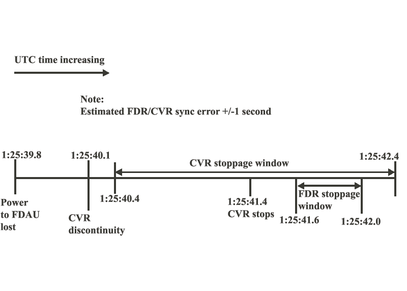
The FDR was powered by the 115 V AC Bus 3. The CVR was powered by the right emergency 115 V AC bus. Both buses are fed from 115 V AC Generator Bus 3. The FDR data indicates that a brief power interruption to the FDAU occurred less than two seconds before the FDR stopped. A warm start re-initialization (re-boot) of the FDAU followed the power interruption. The CVR also showed a discontinuity in the recording within two seconds of the CVR stopping. These interruptions and discontinuities introduce variability in the relative timing between the two recordings and, consequently, the precise stop times.
Estimates of the FDR and CVR relative stop times were based on an analysis of the FDR data at the time of the FDAU re-boot and the CVR discontinuity.
FDR stoppage time
Analysis of the last seconds of recorded FDR data indicate that power to the FDAU was interrupted. The FDR lost synchronization after word 54 of subframe 3, which corresponds to a time of approximately 0125:39.8. Two words containing 1s and 0s were then recorded, followed by 27 words, most of which contained only 0s. The FDR then regained synchronization, repeating subframe 3, although with updated values. The frame counter was incremented by one, and the recording continued for another partial subframe of 22 valid words (duration of 22/64 of a second), after which the recorder stopped. It was determined that a brief power interruption to the FDAU had occurred between word 54 and the pattern of 0s. When the FDR loses signal input from the FDAU, it continues to record for up to two words (duration of 2/64 of a second), based on tests carried out by the FDR manufacturer.
The FDR will coast through a power outage of up to 400 milliseconds, during which time no recording will take place, even though the recorder is still up and running. When power was restored, a FDAU re-boot was initiated, as indicated by the 27 words of 0s (a duration of 27/64 of a second). The re-boot was considered to be a warm start, in that 0s were recorded without a resetting of the frame counter. A warm start re-boot implies a power interruption of anywhere between 10 and 400 milliseconds. The actual duration of the power interruption was not determined. However, it was most likely at least 2/64 of a second long, in order to have recorded the two non-zero words, representing a loss of FDAU signal. Therefore, following the loss of the FDAU signal, there was no recording of data for a maximum period of up to 0.37 seconds (0.4 minus 2/64).
Based on the pattern of the re-boot and the possible duration of the power interruption, the FDR stopped recording between 1.8 and 2.2 seconds after the FDAU power interruption (see above). The time of FDR stoppage would therefore be somewhere between 0125:41.6 and 0125:42.0.
CVR stoppage time
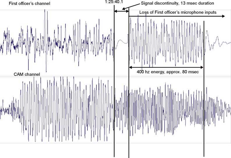
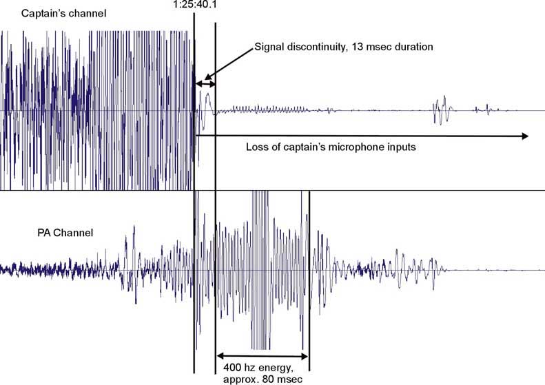
The digitized CVR recording, after time correction, was approximately 32 minutes and 27 seconds long. The arbitrary time reference was converted to UTC (based on FDR and radar information), with the end of recording at approximately 0125:41.4. This stoppage time does not take into account any possible power interruptions that may have occurred during the CVR recording, which would increase the stoppage time. No obvious power interruptions were noted. In addition, the conversion of the CVR arbitrary time to UTC by synchronization with the FDR, has a maximum error band of plus or minus one second, owing to the one-second sample rate of VHF keying. A simultaneous discontinuity in the two radio channel signals, of 13 milliseconds, was noted at 0125:40.1. There was also a significant 400 Hz presence for approximately 80 msec immediately following the discontinuity on the copilot's radio channel. This 400 Hz signature was also simultaneously present on the observer's (PA) audio channel.
Inputs from the captain's and copilot's microphones were lost from the time of the discontinuity to the end of the recording. An attempt was made to determine whether the discontinuity was the result of a power interruption to the CVR. Based on the synchronization used, the time of the discontinuity on the radio channels occurred approximately 0.3 seconds after the time of the FDAU power interruption. It is possible that the CVR discontinuity and FDAU power interruption were related to the same event and therefore occurred at the same time, with the synchronization in error of approximately 0.3 seconds.
The manufacturer of the CVR performed tests on the same model of recorder to characterize the amplitude/time signature of the signal during a power interruption. A signal input of 1 kHz was recorded on all four channels, and a power interruption of 80 milliseconds was applied. The signature was compared for any similarities with the discontinuity and 400 Hz signature observed on the occurrence CVR. The test revealed a distinct roll-off in amplitude when the power was interrupted, and there was evidence of amplitude modulation for a 200 msec when the power was restored.
The test signature did not appear to be similar to the discontinuity on the occurrence CVR, as depicted above. Since all four channels and the bias oscillator are powered by the same source, a power interruption would likely affect the four channels simultaneously. The occurrence signatures from the four tracks, however, were dissimilar. The CVR has a test capability that, when activated, records a 600 Hz test tone sequentially on all four channels. The tone is also recorded on normal start up and would be expected to be generated following the restoration of power after a power interruption. The test tone was not evident on any of the CVR channels on the occurrence recording. Based on the available information, it does not appear that a power interruption to the CVR occurred at the time of the discontinuity and 400 Hz signature, or at any other time during the recording. It is more likely that the two radio channels and possibly the remaining channels on the occurrence CVR experienced some form of electrical interference at the end of the recording.
Relative stoppage times of FDR and CVR
The relative stop times of the FDR and CVR depend on two unknowns, primarily the duration of the FDAU power interruption and the time synchronization. From the synchronization, the FDAU power interruption and the CVR discontinuity were 0.3 seconds apart. Since there is a tolerance of plus or minus one second on the synchronization, and it is possible that one event may have caused the FDAU power interruption event and the CVR discontinuity, it could be assumed that the power interruption and discontinuity were coincident. If the two recordings were synchronized using this point, then the CVR stopped at least half a second before the FDR. The synchronization point using VHF keying (used as the reference for the investigation) and the synchronization point that assumes the power interruption and discontinuity were coincident suggest that the FDR and CVR did not stop simultaneously. However, because it could not be determined whether the power interruption and discontinuity were coincident, and there is a tolerance in the VHF keying synchronization method, it is also possible that the FDR and CVR stopped simultaneously.
Possible causes for premature stoppage of flight recorders
The crew had referenced the CABIN BUS switch, which is the first item on the Swissair Smoke/Fumes of Unknown Origin Checklist. The checklist also requires rotating the SMOKE ELEC/AIR selector sequentially into three possible positions (3/1 OFF, 2/3 OFF and 1/2 OFF), pausing at each position to see whether the smoke diminishes. Each position turns off the associated electrical and pneumatic system (one third of each system). Selection of the 3/1 OFF position would stop both recorders at the same time, since the 115 AC Generator Bus 3 is taken off-line in the 3/1 OFF position.
The SMOKE ELEC/AIR selector is believed to have been fully rotated through the various positions during the final minutes of the flight. For the flight recorders to have stopped through the use of the SMOKE ELEC/AIR selector, either the selector remained in this position for the remainder of the flight (which it did not) or other multiple failures occurred simultaneously.
The flight data revealed that the ADC-1 was not reporting to the FDR; that is, NDU was recorded about half a minute before the flight recorders stopped. The radar data, sampled approximately once every five seconds, showed that the Mode C (altitude information) from the transponder was also lost at about this time. If ADC-1 was supplying the transponder in use (typically ATC-1 for odd flight numbers, as was this flight) with Mode C altitude information, then the loss of Mode C would be expected when ADC-1 went NDU. The loss of ADC-1 would also have caused the captain's primary flight display to show Xs in place of air data parameters, if ADC-1 were the source in use. At this point in the flight, the copilot was flying the aircraft and the captain was troubleshooting. The CVR indicated that the copilot's electronic flight instrument displays then went blank, about 8 to 9 seconds before the flight recorders stopped, and the copilot made a reference to having to use the standby instruments.
About 9 seconds after the flight recorders stopped, the Mode C was restored. It is plausible that when the copilot's displays went blank and he was forced to use the standby instruments, the captain decided to restore valid air data on his electronic displays since he would have had no ADC-1 information. It would, therefore, have been reasonable to select ADC-2 as an alternate source of data for the captain's displays. This action would account for the restored Mode C altitude, assuming ADC-2 was still functional. ADC-2 is on the right emergency 115 V AC bus, fed by Generator Bus 3, the same generator bus that powers the flight recorders and the first position of the SMOKE ELEC/AIR selector. This scenario implies that the SMOKE ELEC/AIR selector was not rotated and was not the cause of the flight recorder stoppage.
Additionally, the FDAU exhibited a power interruption less than 2 seconds before the FDR stopped, whereas, on an other occurrence (Delta Airlines MD-11, N805DE, 9 October 1998), stoppage with the SMOKE ELEC/AIR selector in the 3/1 OFF position reportedly did not result in this characteristic. It is considered highly coincidental (and therefore unlikely) for a SMOKE ELEC/AIR selector action to have been made so close to the power interruption in the FDAU.
Physical evidence from the wreckage also suggested that the numerous fuel pumps powered by Generator Bus 3 were operational at the time of impact with the water.
The CABIN BUS switch was mentioned on the flight deck before the action was made to remove power to the cabin. Since the movement of the SMOKE ELEC/AIR selector to the first position is a significant action (compared to use of the CABIN BUS switch) affecting the operational status of the aircraft, it would be reasonable to also expect a verbal communication before that action was made. There was no verbal communication from either crew member with respect to operation of the SMOKE ELEC/AIR selector. In the seconds before the recorder stopped, when the copilot's displays went blank, it is possible that problems associated with the basic flight of the aircraft were escalating to the point where both crew members were focused on the task of flying the aircraft and restoring instrument display information.
It is considered unlikely that the SMOKE ELEC/AIR selector was the cause of the recorder stoppage. The flight recorders probably stopped as a result of problems with the continuity of the electrical system.
FDR anomalies
The parameters that recorded fault codes were associated with the following LRUs: FCC-1, FCC-2, DEU-1 and ADC-1. Each LRU performs signal monitoring; when a fault is detected the LRU generates an NCD fault code. For example, the FCC-1 contains monitors that can detect shorts to ground on input wires, open input wires, loss of excitation, or incorrect power phasing. Upon detecting any of these failures, the FCC-1 will flag the anomalous synchro output as NCD. The NDU fault code is generated by the FDAU when it detects a loss of bus input. The loss can be caused by a number of possible failures, including the opening of the input bus wire or the shorting-to-round of the input bus wire.
According to the manufacturer, when a fault is detected by the FDAU, it will continuously output static data (no longer updated) for a specified time period, followed by the generation of the NDU fault code. The output of the fault code continues until the fault condition no longer exists. The last valid data (or NCD fault code, if FDAU was outputting NCD at initiation of NDU condition) will be generated for a count of four samples, prior to the output of the NDU fault code. Information from the FDAU manufacturer indicates that the duration of the static data is dependent on the subframe number being recorded at the time the fault occurs, and the sample rate of the parameter. For parameters recorded once per second, the duration of static data is estimated to be in the range of approximately 5 to 8 seconds. For parameters recorded once every 2 seconds, the estimated duration of static data is in the range of approximately 12 to 13 seconds. These durations are considered approximate; variations may exist. Analysis of the accident flight data indicated that some of the static data preceding the NDU output was generated for the expected duration, while other data did not match the estimated times. For those parameters (at varying sample rates) that recorded the NDU fault code and that were sourced from FCC-1, the period of static data ranged from approximately 10 to 16 seconds (most parameters were static for 12 to 13 seconds). For those parameters (at varying sample rates) that were sourced from ADC-1, the period of static data was approximately 6 to 7 seconds.
The earliest parameter that recorded the NCD fault code was "Angle of Attack Right 2B", at approximately 0124:58. The parameter source was FCC-1 Channel B. Within the next 2 seconds "Spoil RT 5" and then "Flap ROB" also began to record the NCD fault code, also sourced from FCC-1 Channel B. According to the manufacturer of the aircraft, the FDAU receives output from channels A and B of FCC-1 only via the Channel A side. If a problem occurs with the Channel A side such that Channel A no longer processes Channel B data, the LRU will generate the NCD fault code for the unprocessed Channel B parameters. Since the sampling rates of the parameters were not the same, the different NCD start times were likely a result of sampling effects.
The earliest parameter that recorded the NDU fault code was "Spoil LT 3", at approximately 0125:09. The parameter source was FCC-1. An additional 10 parameters also began to record the NDU fault code in sequence over the next two seconds. The difference in the sampling rates of the parameters likely accounts for the different start times of the NDU fault codes. The loss of primary power to FCC-1 Channel A would result in the loss of FCC-1 output to the FDAU and generation of the NDU fault codes. When primary power is lost, 1.5 seconds of back-up power is provided to the FCC Channel A side, during which time no data processing of the Channel B side occurs, resulting in the initial NCD fault code, which precedes the NDU condition. When considering the length of back-up power and the 12 to 13 second delay in recording the fault codes, during which time static data was recorded, the time of the FCC-1 Channel A loss was approximately 0124:57. None of the parameters from FCC-2 recorded fault codes during the last minute of the recording, suggesting that FCC-2 was functional up to the time of flight recorder stoppage.
At approximately 0124:59.7, the first of two DEU-1 discrete parameters (FMA 2 - Vertical) changed from "Hold - White" to "No Display", indicating that the FMA display went blank. The second DEU-1 discrete (FMA 1 - Roll) changed from "Heading - White" to "No Display" at 0125:00.3. The DEU parameters require data from FCC-1 in order to display the associated FMA modes.
The Computed Airspeed, Pressure Altitude, and TAT parameters recorded NDU fault codes at approximately 0125:14. These parameters were sourced from ADC-1. When considering the approximate 6 to 7 seconds of static data preceding the fault codes, it is estimated that a fault with ADC-1 occurred at approximately 0125:07. The ATC Transponder 1 is believed to have been in use, as Swissair procedures require that this system be used for odd-numbered flights (e.g., SR 111). The ATC Transponder 1 is normally fed from ADC-1. The loss of ADC-1 at the estimated time, based on the fault codes, is in agreement with the last radar Mode C return at 0125:06, before the Mode C was temporarily lost (Mode C was regained at 0125:50).
Several discrete parameters recorded changes during the time the parametric data recorded fault codes in the last minute of the recording. Some of these changes in the discrete data represented anomalous or non-real events, likely occurring as a result of damage to electrical systems, as opposed to being the result of crew actions. In other instances, the changes were considered to be real events that occurred as a result of system-related damage. The first discrete parameter to indicate a change in status (that was considered to be a result of system-related damage) was FMA 2 - Auto Flight, which changed from "A/P 2 - Cyan" to "A/P 2 - OFF Red", indicating autopilot disconnection. This is considered to have been an actual event, as opposed to being anomalous. A review of the control surface deflections suggested that the disconnection was not a result of inadvertent manual control inputs by the crew. There was also no indication that the crew had intended to manually disconnect the autopilot. Radio communications with ATS following the autopilot disconnection suggested that the crew was forced to fly the aircraft manually. Furthermore, the autopilot warbler, which had begun to cycle at the time of the disconnection, continued to cycle to the end of the CVR recording. It would be reasonable to expect the crew to switch to the other autopilot and to try to silence the warbler. The fact that they were unable to use the other autopilot and unable to silence the warbler suggests that a fault in the system had caused the disconnection.
The discrete parameter Yaw Damp. Lower 1A, provided from FCC-1, was the second parameter to indicate a change in status as a result of system-related problems. While the 1A channel of the lower yaw damper changed from "On" to "Off" at 0124:54, the 1B channel side remained "On" suggesting that the change was not a crew action, but a result of system damage.
A failure associated with FCC-1 was consistent with the fault codes, and with the subsequent change in the FMA data to "No Display" (loss of FCC-1 information), occurring at approximately 0125:00. At approximately 0125:15, the four slat sensor parameters, normally provided from DEU-1, indicated what are considered to be anomalous or non-real changes in status, changing from "Retracted" to "Transit" for 25 seconds. These changes are considered anomalous, since there is no flight recorder data concerning aircraft behaviour to indicate that the slats had actually moved from the retracted position. Furthermore, the slat overspeed protection (284 KIAS threshold) would have inhibited slat extension at the 320 KIAS recorded at that time.
At the time of the slat sensor changes, there was a further change in the FMA data that is considered an anomalous or non-real event. The recorded FMA data represents information presented on the captain's FMA displays. Under normal conditions, the captain's SOURCE SELECT switch (label 270) is set to DEU-1, and the recorded FMA data will be based on information from DEU-1. The FDR records the switch position; however, it does not record which DEU is providing information for the FMA data. The FDR recorded the captain's SOURCE SELECT switch as having remained in the DEU-1 position for the entire recorded flight. According to the manufacturer of the FDAU, when the FDAU detects failure of DEU-1 (failure of the bus activity test, which checks for a 1 second update of label 270), it then automatically outputs information from DEU-3 (auxiliary), following the recording of static data, although no specific fault code is generated. The switch to DEU-3 is not recorded on the FDR; the FDR only records the captain's DEU selection, which is retrieved from the selected DEU bus. The recording of anomalous data was likely a result of a failure associated with DEU-1, which is estimated to have occurred at approximately 0125:08. This estimate assumes the recording of 5 to 8 seconds of static data, followed by the switch to DEU-3. Since DEU-3 was not selected during the flight, the parametric data from DEU-3, which included the FMA data, had not been updated, and contained random data from the last re-initialization. Since discrete data, such as the slat sensor data, was output to all three DEUs simultaneously during the flight, DEU-3 therefore contained discrete information that did not represent the actual position of the slats. The last second of recorded FMA data matched the previous values from DEU-1, preceding the switch to DEU-3. This was consistent with the FDAU warm start re-boot sequence, whereby DEU-1 would be temporarily re-selected for approximately 1 second.
At 0125:34 the discrete Yaw Damp. Upper 2A, provided from FCC-2, changed from "On" to "Off." While the 2A channel of the upper yaw damper changed to "Off," the 2B channel side remained "On," suggesting that the change was not initiated by a crew action, but a result of system damage.
According to the manufacturer of the FDAU, the loss of a digital discrete (DITS) input to the FDAU will result in the output of the last valid data until new data is received again. If there is a loss of an analog discrete input to the FDAU, the FDR output will depend on whether the discrete is a series or shunt-type analog discrete. When a loss of signal input occurs for the series and shunt discretes, the FDR output will be 0 and 1, respectively. Therefore, depending on the type of discrete and the state of the discrete at the time of the fault, there may or may not be a change of status when a loss of input signal to the FDAU occurs. For the final minute of FDR operation, during which time fault codes were occurring as a result of system damage, some of the discrete parameters may not have been recording valid information. Although discretes such as Master Warning (DITS) indicated no warnings during the flight, the validity of the information was not known for the final minute of the recording.
During the diversion to Halifax, the digital discrete parameters recorded that all the air conditioning packs, as well as all the air bleeds remained "On" to the end of the recording (sampled every 4 seconds). The Swissair Air Conditioning Smoke Checklist was referenced by the crew on the cockpit voice recording, although it is not known whether the checklist had been performed. This checklist requires various combinations of air packs and air bleeds to be turned off in sequence in order to isolate the source of the smoke. Although the discretes indicated that the air conditioning packs and air bleeds remained on, it is possible that this data was invalid (or static) during the final minute of the recording.
Although the FCC-1, FCC-2, ADC-1 and DEU-1 LRUs are located in the main avionics rack in the avionics bay below the cockpit, they are in separate locations within the rack. There was no evidence of fire damage in the avionics bay. The different locations of the LRUs, outside of the fire-damaged areas suggest that the problems were associated with system wiring external to the avionics bay, rather than with the LRUs themselves.
Weather diversion, 13-minute communications gap, air page selections
A review of the FDR data was undertaken to determine whether any anomalies existed from the time the aircraft departed New York's JFK airport to the point when the FDR stopped recording. Although the entire data set for the occurrence flight was reviewed, several time segments were of particular interest, including the following:
- Diversion around weather during the initial climb-out (0017:30 to 0025:30)
- Initial Air Page selection (0025:30 to 0040:30)
- Time segment, including 13-minute gap in radio communications, and up to the time of initial detection of odour/smoke (0032:30 to 0112:30)
- Second Air Page selection (0112:30 to 0122:30)
Although there were no reports from the aircraft that a lightning strike had occurred during the weather diversion, data was reviewed for any HIRF/EMI-related anomalies stemming from a lightning strike. Of particular interest were possible electrical anomalies:
- Synchronization losses;
- Wrong length subframes (data drop-outs or spikes); or
- FDAU resets (frame counter resets as a result of power interruptions).
There was also the possibility of transient voltages affecting sensor outputs and resulting in the recording of invalid data, data spikes, or the generation of fault codes.
It should be noted that neither system voltages nor temperatures (with the exception of TAT) were recorded parameters with Swissair's MD-11 FDR configuration. No FDR parameter anomalies were found during the weather diversion or at any other time during the flight, with the exception of the fault codes and power interruption to the FDAU, which occurred within the final 90 seconds of the FDR recording. No warnings or failures of any kind were recorded at any time during the flight, leading up to the final 90 seconds of the FDR recording, when fire-related system damage was occurring.
The SD was initially selected to the Air Page at 0025:56 (possibly 64 seconds earlier). The Air Page remained selected for up to approximately 15 minutes (considering the sampling rate). A second and final selection of the Air Page was recorded at 0112:52 (possibly 64 seconds earlier), following the crew's initial detection of a odour/smoke. The SD remained on the Air Page for as long as 9.5 minutes. Information on the Air Page includes the following:
- Duct temperatures, including overheat condition
- Zone temperatures and set temperatures
- Pack temperatures, including overheat condition
- Smoke and heat detector indications
- Duct and flow line information, including manifold failure
- Air conditioning pack information, including overheat and manifold failure
- Engine bleed pressures and temperatures, including limit exceedances
- Bleed valve, isolation valve, tail anti-ice valve, and wing anti-ice valve operation, including uncommanded position and wing manifold fail
- Cabin ALT, Cabin Differential Pressure, Cabin RATE, and Cabin LAND readouts
- OUTFLO (valve) and APU Air (Load Control Valve) readouts
- PAX Load readout
With respect to the Air Page selection, the FDR parameters associated with the Air Page are
- A/CFootnote 1 Pack OFF discrete, APU N1, APU N2, APU Fire Warn discrete;
- Bleed Air OFF discrete;
- Cabin Altitude;
- Cabin Pressure Warn discrete;
- Cargo Heat Aft and Cabin Heat Fwd discretes;
- Pneu Mfld Sup (pneumatic manifold supply failure) discrete;
- Sys Display Status; and
- Tail Anti-ice discrete and Wing Anti-ice Valve Pos discrete.
None of these parameters indicated that there was an anomaly or warning of any kind during the Air Page selections or at any other time during the flight. During the final minute of FDR operation there is evidence of progressive system failures, generation of fault codes, and a power interruption. Certain parametric data indicated invalid information or fault codes during this time; however, since no fault codes are generated for discrete data, it is not possible to discern whether discretes were valid for the final minute of the recording. A search was also undertaken for any FDR anomalies that might be related to the 13-minute radio communications gap; however, none were found for this segment of the flight.
No other recorded parameter exhibited anything considered unusual. The outboard ailerons, spoiler positions and ND Weather Radar parameter revealed some recording inconsistencies, which were considered insignificant. In cruise, the outboard ailerons are normally locked out and are both drooped a few degrees. The right outboard aileron recorded a value of 5.6 degrees down during the cruise phase, compared to 3 degrees down for the left outboard aileron. This discrepancy was also noted on the previously recorded flight, and is not considered to be relevant to the accident. The Spoil LT 5 position changed from 0 counts (0 degrees position–spoilers retracted) to maximum counts (1023) intermittently during the flight, opposite to the other spoiler positions. This was also observed with both Spoil LT 5 and Spoil LT 3 positions on previously recorded flights. The spoiler discrepancies were attributed to the absence of a recorded sign bit for the spoiler parameters. According to the aircraft manufacturer, the spoilers are signed parameters, although the documentation does not indicate this. The sign bit is not recorded to enable the recording of a higher resolution of spoiler position within the 10-bit allocation for spoilers in the recording map. For a 10-bit signed parameter, a count of 1023 in two's complement would convert to a slightly negative angle (−0.1 degrees) of the spoiler position. It was determined that the definition of the ND-Weather Radar OFF discrete in the recording map specification for the MD-11 was incorrect.
Flight animation
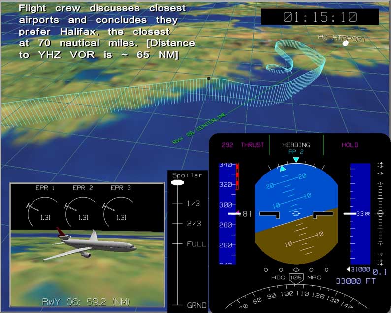
A computer flight animation was generated to depict the sequence of events in real time. The animation contains a representation of a primary flight display for the MD-11 aircraft, an inset with a close-up of the aircraft along the flight path, the overall location of the aircraft on the flight path, a written commentary of key events, and the ATS voice recording synchronized to the animation. Key information from the CVR is depicted in the animation, but owing to the privilege under the Canadian Transportation Accident Investigation and Safety Board Act, the audio from the recording is purposely not included. A two-dimensional overlay of a 1 km satellite image covering the geographic area of the flight was added to the flight animation, along with an extended runway centreline, extending 60 nm from the threshold.
A ground track was developed using the FDR recorded data comprising inertial ground speed, drift angle, and magnetic heading. Aircraft displacement was determined by mathematical integration of the ground speed data. The ground track was calculated from the start of the take-off out of JFK to just prior to the final point of impact. Since the FDR stopped recording approximately six minutes before the crash, the primary surveillance radar data was used for the ground track calculation for the latter portion of the flight. By positioning the start of the ground track at the threshold of JFK Runway 13R, it was found that the end point of the ground track corresponding to the time of flight recorder stoppage did not precisely match the radar data position at the time the recorder stopped. This was probably owing to mathematical integration and inertial data errors, and radar data inaccuracies. To synchronize the calculated ground track with the radar track at the time of recorder stoppage, the ground track based on inertial data was stretched by applying a weighted offset to the x and y coordinates. Although it was found that the stretch required was small, approximately 0.02%, given the inaccuracies in the calculation method and the quality of the FDR and radar data, the position of the aircraft between take-off and the time of impact was considered approximate.
The altitude profile for the segment up to the point of the flight recorder stoppage was based on the recorded pressure altitude. For the final 5.5 minutes of the flight, when no altitude or FDR data was recorded, an average rate of descent was assumed between the time of the last transponder Mode C return and the time of impact. The last Mode C altitude of 9 700 feet was recorded at 0126:04, approximately 5 minutes and 14 seconds before impact with the water at 0131:18. Assuming the descent was begun at the time of the last Mode C return, an average rate of descent of approximately 1 800 feet per minute was possible. The spacing of the primary surveillance radar returns after the loss of Mode C information suggested that the forward speed of the aircraft was nearly constant during the right-hand turns. This, in turn, suggested that the aircraft descended at a nearly constant rate. Any large changes in the descent rate during this time likely would have been characterized by noticeable changes in the ground speed and, consequently, the spacing of the primary surveillance radar returns. Lacking more precise data, the final 5.5 minutes of the flight animation was depicted with a constant rate of descent from the 10 000 foot level to the surface of the ocean, although there may have been deviations from the depicted profile. The animation stops at the last primary radar hit, at an assumed altitude of approximately 600 feet.
The flight animation depicts a representation of the PFD, which contains both recorded data and derived information. The recorded data includes computed airspeed, pressure altitude, magnetic heading, EPR, pitch and roll attitude, and FMA automatic flight modes, all recorded at a rate of 1 Hz. The spoiler lever position is represented by the position of the left Spoiler Panel 5, recorded once every 2 seconds, as the actual spoiler lever position was not a recorded parameter. The FMA display includes Speed, Lateral, and Vertical modes, based on both FMA-1 and FMA-2 data. Selected airspeed and selected altitude were recorded once every 64 seconds. The recorded values were displayed and held until the next sample was recorded, even though it is possible that the selected parameter may have changed between the recorded samples. Pitch and roll data were used to drive the PFD attitude display. The vertical rate in feet per minute was calculated by differentiating the pressure altitude data. The resolution of the pressure altitude data was such that some mathematical smoothing of the data was initially required to correct for noise. Computed airspeed was recorded on the FDR; however, since the PFD also displays Mach number at the higher airspeeds, this parameter was calculated from the recorded airspeed and pressure altitude data. In addition, a representation of the "barber pole" showing the maximum operating speed, VMO/MMO, was calculated as a function of pressure altitude, assuming wingtip fuel of at least 90%. During the last minute of the FDR recording, numerous parameters recorded fault codes as a result of fire-related system damage. The generation of the fault codes is evident in the PFD display, as numerous parameters suddenly change in value.
The inset view of the flight animation depicts the approximate ground distance to Halifax's Runway 06 threshold in nautical miles, based on the recorded inertial latitude/longitude data.
For the flight animation segment following the FDR stoppage (final six minutes), the flight profile is based on the primary surveillance radar returns. Also displayed are approximations of the aircraft attitude, altitude, speed, vertical rate, and heading based on radar data calculations.
List of FDR parameters
- A/C Pack 1 OFF
- Elev Pos LT OUTBD
- Eng 3 Oil Press Low
- A/C Pack 2 OFF
- Elev Pos RT INBD
- Eng 3 Oil Qty
- A/C Pack 3 OFF
- Elev Pos RT OUTBD
- Eng 3 Oil Temp
- Aileron Pos LT INBD
- Emer Lights Disarm
- Eng 3 Throttle Res. Angle
- Aileron Pos LT OUTBD
- Eng 1 Anti-ice Valve Pos
- Eng 3 Thrust Rev
- Aileron Pos RT INBD
- Eng 1 EGT
- FCC Sel - CAPT
- Aileron Pos RT OUTBD
- Eng 1 EPR (P&W)
- FCC Sel - FO
- Altitude: Radio 1
- Eng 1 FADEC Sel
- Flap LIB
- Altitude: Radio 2
- Eng 1 Fire Warn
- Flap LOB
- Angle of Attack Lt 1A
- Eng 1 Fuel Flow
- Flap Posn
- Angle of Attack Lt 1B
- Eng 1 Fuel Valve Open
- Flap RIB
- Angle of Attack Rt 2A
- Eng 1 N1 Fan Speed
- Flap ROB
- Angle of Attack Rt 2B
- Eng 1 N2 Core Speed
- Flight Director Active
- APU Fire Warn
- Eng 1 Oil Press PSI
- FMA 1 - Auto Speed Protect
- APU N1
- Eng 1 Oil Press Low
- FMA 1 - Roll
- APU N2
- Eng 1 Oil Qty
- FMA 1 - Roll Armed
- Baro Set Capt
- Eng 1 Oil Temp
- FMA 1 - Roll Flash
- Baro Set FO
- Eng 1 Throttle Res. Angle
- FMA 1 - Speed
- Bleed Air 1 OFF
- Eng 1 Thrust Rev
- FMA 1 - Speed Flash
- Bleed Air 2 OFF
- Eng 2 Anti-ice Valve Pos
- FMA 2 - Auto Flight
- Bleed Air 3 OFF
- Eng 2 EGT
- FMA 2 - Auto Throttle
- Brake Pedal Posn L
- Eng 2 EPR (P&W)
- FMA 2 - Ground Prox.
- Brake Pedal Posn R
- Eng 2 FADEC Sel
- FMA 2 - Land Armed
- Brake Press LT Sys2
- Eng 2 Fire Warn
- FMA 2 - Land Mode
- Brake Press RT Sys1
- Eng 2 Fuel Flow
- FMA 2 - Profile
- C of G
- Eng 2 Fuel Valve Open
- FMA 2 - Vertical
- Cabin Altitude
- Eng 2 N1 Fan Speed
- FMA 2 - Vertical Alert
- Cabin Pressure Warn
- Eng 2 N2 Core Speed
- FMA 2 - Vertical Flash
- Cargo Heat Aft
- Eng 2 Oil Press PSI
- FMS Sel - CAPT
- Cargo Heat Fwd
- Eng 2 Oil Press Low
- FMS Sel - FO
- Computed Airspeed
- Eng 2 Oil Qty
- Frame Counter
- Date (Day/Month)
- Eng 2 Oil Temp
- Gear Compress Nose-L
- DEU Recorded
- Eng 2 Throttle Res. Angle
- Gear Compress Nose-R
- DEU Sel - CAPT
- Eng 2 Thrust Rev
- Gear Down & Locked CTR
- DEU Sel - FO
- Eng 3 Anti-ice Valve Pos
- Gear Down & Locked LH
- DH Warn
- Eng 3 EGT
- Gear Down & Locked Nose
- Display Unit Config
- Eng 3 EPR (P&W)
- Gear Down & Locked RH
- DME1 Dist
- Eng 3 FADEC Sel
- Gear Unsafe CTR
- DME1 Freq
- Eng 3 Fuel Valve Open
- Gear Unsafe RH
- DME2 Freq
- Eng 3 Fuel Valve Open
- Gear Unsafe RH
- Documentary Data
- Eng 3 N1 Fan Speed
- Gross Weight
- Drift Angle
- Eng 3 N2 Core Speed
- Ground Speed
- Elev Pos LT INBD
- Eng 3 Oil Press PSI
- GS Dev 1
- GS Dev 2
- ND-WX Radar
- Slat R2
- HF 1 Keying
- Overspeed Warning
- Slat R4
- HF 2 Keying
- Park Brake Set
- Slats Disagree
- Hydraul Oil Qty-R1
- PFD-ALT Fail
- Spoil LT 3
- Hydraul Oil Qty-R2
- PFD-ALT Miscompare
- Spoil LT 5
- Hydraul Oil Qty-R3
- PFD-ATT Fail
- Spoil RT 3
- Hydraul Sys 1 Press Low
- PFD-ATT Miscompare
- Spoil RT 5
- Hydraul Sys 2 Press Low
- PFD-CAS Fail
- Spoilers Armed
- Hydraul Sys 3 Press Low
- PFD-FD Fail
- Stab Out Of Trim
- ILS-1/MLS-1 Sel
- PFD-Feet/Meters Sel
- Stab. 1 Posn
- ILS-2/MLS-2 Sel
- PFD-HDG Fail
- Stab. 2 Posn
- IRS Sel - CAPT
- PFD-HDG Miscompare
- Stall Warn
- IRS Sel - FO
- PFD-HDG/Track Sel
- Sync codes
- Lateral Accel
- PFD-IAS Miscompare
- Sys Display Status
- Latitude Position
- PFD-IAS/MACH Sel
- T/O Config Warn-Flaps
- Loc Dev 1
- PFD-In/hP Sel
- Tail Anti-ice
- Loc Dev 2
- PFD-MACH Fail
- TAT
- Longitude Position
- PFD-Mag/True Sel
- TAT Probe Heat
- Longitudinal Accel
- PFD-V Speed Fail
- TCAS Display
- LSAS LIB Fail
- PFD-V Speed/FPA Sel
- TCAS SL
- LSAS LOB Fail
- Pitch Attitude
- Thrust Limit Mode
- LSAS RIB Fail
- Pitot Stat Heat-AUX
- Total Fuel Quantity
- LSAS ROB Fail
- Pitot Stat Heat-Capt
- Track Angle (True)
- Magnetic Heading
- Pitot Stat Heat-FO
- True Heading
- Marker Middle
- Pneu Mfld Sup
- UTC
- Marker Outer
- Pressure Altitude
- Vertical Accel
- Master Warning
- Roll Attitude
- VHF 1 Keying
- Mode 5 Visual
- Rudder Pos. (Lower)
- VHF 2 Keying
- ND-APPR Mode Sel
- Rudder Pos. (Upper)
- VHF 3 Keying
- ND-CDI Source Fail
- SATCOM 1 Keying
- VOR/NAV 1 Freq
- ND-HDG Fail
- SATCOM 2 Keying
- VOR/NAV 2 Freq
- ND-HDG Miscompare
- Select Baro Min #1 (DH)
- Wind Direction
- ND-Map Fail
- Select Baro Min #2 (DH)
- Wind Speed
- ND-Map Mode Sel
- Selected Airspeed
- Wing Anti-ice Valve Pos
- ND-No Plan Mode
- Selected Altitude
- Yaw Damp. Lower 1A
- ND-Plan Mode Sel
- Selected Flight Path Angle
- Yaw Damp. Lower 1A/1B
- ND-Position Miscompare
- Selected Heading
- Yaw Damp. Lower 1B
- ND-Predict Wshear-Alert
- Selected Rwy Heading
- Yaw Damp. Upper 2A
- ND-Predict Wshear-Warn
- Slat L2
- Yaw Damp. Upper 2A/2B
- ND-VOR Mode Sel
- Slat L4
- Yaw Damp. Upper 2B
Invalid and valid parameters in last three subframes of FDR data
0125:39 Invalid parameters in last 10 words of subframe 3 of 4. All other parameters in the first 54 words of the subframe trend with previous values.
- Aileron Pos LT OUTBD
- Eng 3 FADEC Sel
- Hydraul Sys 2 Press Low
- APU Fire Warn
- Eng 3 Fire Warn
- Hydraul Sys 1 Press Low
- Cabin Pressure Warn
- Eng 3 Oil Press Low
- IRS Sel - CAPT
- Elev Pos LT OUTBD
- Eng 3 Throttle Res. Angle
- IRS Sel - FO
- Eng 1 Fire Warn
- Flap Posn
- Master Warning
- Eng 1 Oil Press Low
- Flight Director Active
- Pitch Attitude
- Eng 2 FADEC Sel
- FMA 2 - Profile
- Rudder Pos. (Lower)
- Eng 2 Fire Warn
- FMA 2 - Ground Prox.
- Slats Disagree
- Eng 2 Oil Press Low
- Gear Down & Locked CTR
- Vertical Accel
- Eng 3 EGT
- Gear Down & Locked Nose
- Eng 3 EPR (P&W)
0125:40 Invalid parameters in the last 9 words of subframe 3 of 4. All other parameters in the first 55 words of the subframe trend with previous values.
- Aileron Pos LT OUTBD
- Eng 3 FADEC Sel
- Hydraul Sys 1 Press Low
- APU Fire Warn
- Eng 2 Fire Warn
- Hydraul Sys 2 Press Low
- Cabin Pressure Warn
- Eng 1 Oil Press Low
- IRS Sel - CAPT
- Elev Pos LT OUTBD
- Eng 2 FADEC Sel
- IRS Sel - FO
- Eng 3 EGT
- Eng 3 EPR (P&W)
- Master Warning
- Eng 2 Oil Press Low
- Flap Posn
- Pitch Attitude
- Eng 3 Oil Press Low
- Flight Director Active
- Rudder Pos. (Lower)
- Eng 1 Fire Warn
- Gear Down & Locked CTR
- Slats Disagree
- Eng 3 Fire Warn
- Gear Down & Locked Nose
- Vertical Accel
0125:41 Valid parameters in the first 22 words of subframe 4 of 4. The last 42 words in the subframe were not recorded, as the recording ended.
- Aileron Pos LT INBD
- HF 2 Keying
- Pitch Attitude
- Altitude: Radio 2
- HF 1 Keying
- Roll Attitude
- Angle of Attack
- Lateral Accel
- Slat R2
- Brake Press RT Sys1 (psia)
- Lateral Accel
- Slat L4
- Computed Airspeed
- Longitudinal Accel
- Spoil LT 5
- Drift Angle
- Longitudinal Accel
- TCAS SL (bit 21)
- Elev Pos LT INBD
- LSAS ROB Fail
- TCAS SL (bit 20)
- Emer Lights Disarm
- LSAS RIB Fail
- TCAS SL (bit 19)
- Eng 1 Throttle Res. Angle
- LSAS LOB Fail
- TCAS Display
- Eng 1 Thrust Rev
- LSAS LIB Fail
- Vertical Accel
- Eng 1 EPR (P&W)
- Marker Outer
- Vertical Accel
- Frame Counter
- Marker Middle
- Vertical Accel
- Gear Compress Nose-R
- ND-Predict Wshear-Warn
- VHF 1 Keying
- Gear Compress Nose-L
- ND-Predict Wshear-Alert
- VHF 2 Keying
- Ground Speed
- Overspeed Warning

