Associated links (A98H0003)
Landing gear
Landing Gear System Description
The landing gear system consists of two main gear (left and right main landing gear), a center gear, and a nose gear. The left and right main landing gear incorporate a four-wheel twin bogie beam assembly with individual wheel brakes. The center gear incorporates a dual wheel assembly with individual wheel brakes. The nose gear has a steerable shock strut with dual wheels and no brakes. The left and right main landing gear retract inward and, in the stowed position, the gear strut is aligned horizontally with the wheels oriented inboard. The forward wheel assemblies on the left main landing gear are numbered 1 and 2, and the aft wheel assemblies are numbered 5 and 6. The forward wheel assemblies on the right main landing gear are numbered 3 and 4, and the aft wheel assemblies are numbered 7 and 8. The center gear retracts forward, and the wheel assemblies are numbered 9 and 10. The nose gear retracts forward and, in the stowed position, the shock strut is inclined slightly upward.
The landing gear system is hydraulically operated. Hydraulic System 3 provides normal gear extension and retraction.
Landing gear system examination
Main landing gear
Left main landing gear
The left main landing gear was recovered as a single unit.
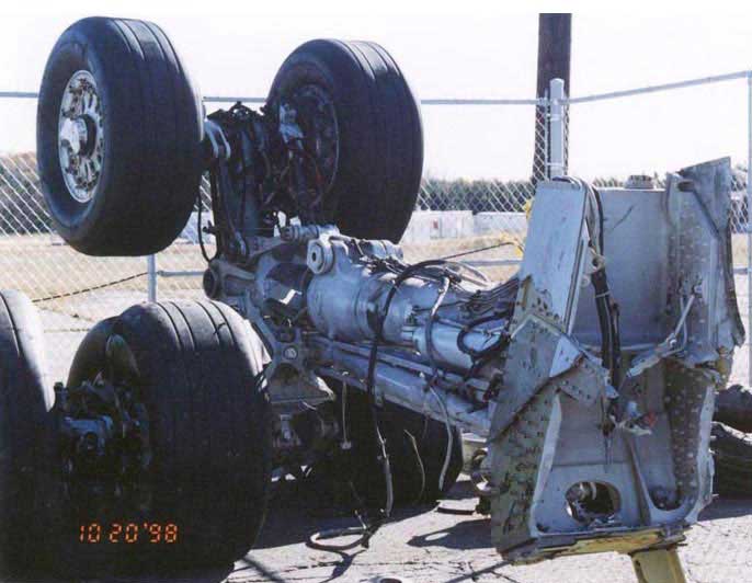
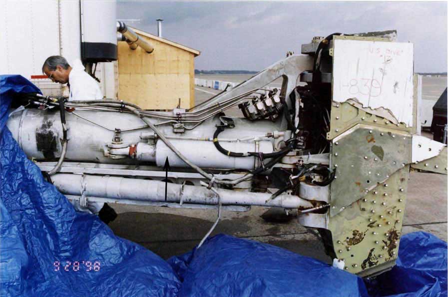
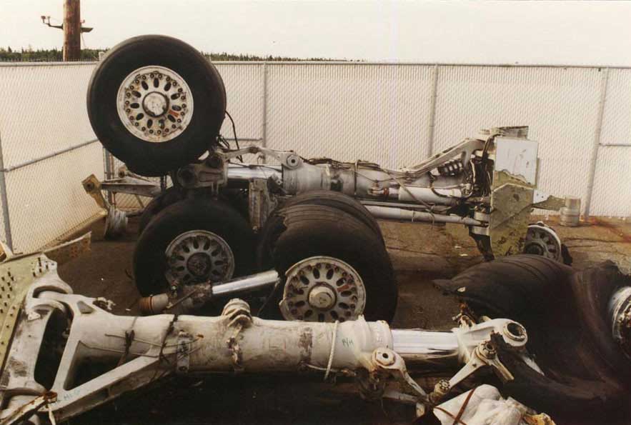
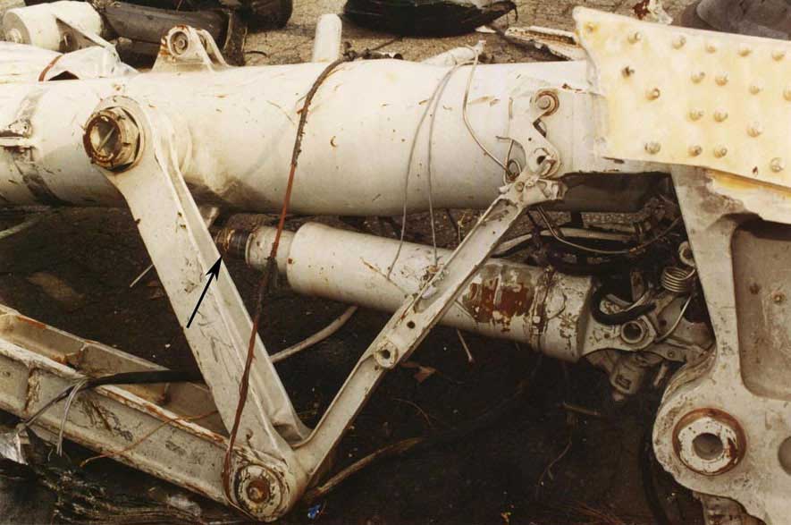
The upper trunnion pivot points were attached to the landing gear wing box structure, which had torn free from its surrounding structure. The landing gear was in the stowed position as oriented to the wing box structure. The landing gear assembly was intact; the truck beam and its four wheel and tire assemblies were attached. Tires 1, 2, and 5 were ruptured and deflated. Tire 6 was inflated. The fixed side brace link, the upper and lower side brace links, the downlock link, and the retract cylinder were attached and oriented in the retracted position.
Right main landing gear
The right main landing gear was recovered in several pieces.
The upper trunnion pivot points were attached to the landing gear wing box structure, which had torn free from its surrounding structure. The landing gear was in the stowed position as oriented to the wing box structure. The lower truck assembly was detached from the lower strut and was fractured in numerous locations. Wheel assemblies 3 and 4 were separated into individual components. The rim of Wheel Assembly 4 was fractured into small segments and the tire was detached. Wheel Assembly 3 was intact, but the tire was ruptured and deflated. Wheel assemblies 7 and 8 were detached from the truck assembly as a unit. Both tires were ruptured; Tire 8 exhibited greater damage. The upper and lower side braces, the downlock link, and the retract cylinder were intact. The upper end of the upper side brace was detached from the support structure and the side brace was pulled away from the strut. The retract cylinder had a partial extension of 60 mm, which is consistent with the movement of the lower gear leg at the time of impact or during the recovery phase.
Center gear
The center gear was extensively damaged and was recovered in several pieces. The retract actuator had broken away from the gear assembly and the actuator was in the fully retracted position.
The strut assembly was detached from the upper strut housing. The lower leg assembly was intact, but tires 9 and 10 were ruptured and deflated.
Nose gear
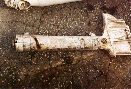
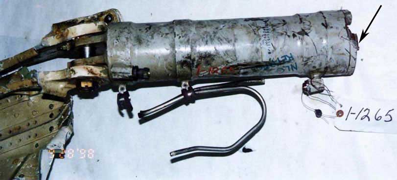
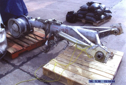
The nose gear was recovered in several pieces. The upper trunnion pivot points were attached to structural support members. The nose gear actuator had separated from the nose gear assembly and the actuator was in the fully retracted position.
The left tire and wheel assembly were detached, and the axle was fractured at mid-span.
The right wheel was attached to the axle and the tire was torn free from the rim. The strut was fully compressed; the strut air valve and cylinder cap were not recovered.
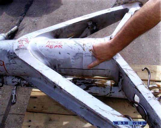
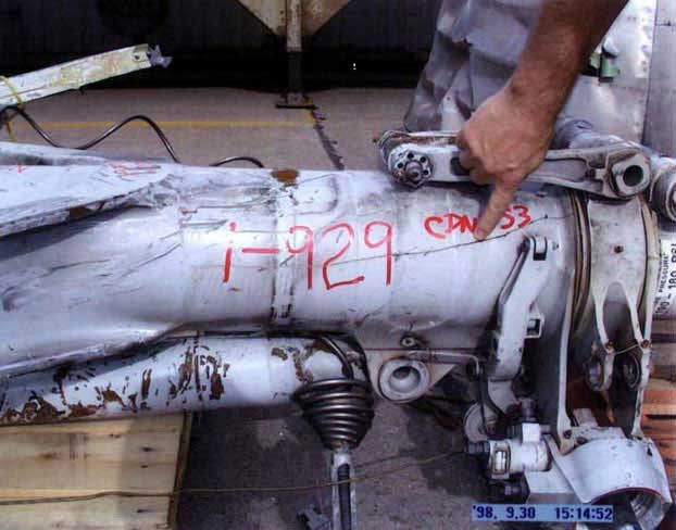
The strut outer cylinder wall had two longitudinal cracks-one on the right side of the strut between the trunnion frames, and one on the left side of the strut below the trunnion lower frame.
The damage to the strut outer cylinder wall and to the strut air valve is consistent with the lower leg assembly being driven rearward into the strut housing with the landing gear in the retracted position.
Landing gear system determination
An examination of the landing gear system indicated that all four landing gear assemblies were in the stowed position at the time of impact. The right main landing gear displayed greater overall damage than the left main landing gear.
