Associated links (A98H0003)
Standby flight instruments
Standby attitude indicator
Description
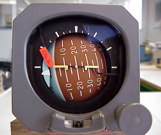
The SAI or "gyro horizon" installed in HB-IWF (the occurrence aircraft) was manufactured by Thomson-CSF Sextant (PN H321BVM1). The spherical display drum is divided into two colours: blue indicates "climb" and brown indicates "dive." The SAI is powered by the battery bus through CB B1-865 located in the overhead CB panel at position C-01. The battery bus is in turn redundantly powered by TR 1, TR 2A, TR 2B, and TR 3.
From CB B1-865, wire B201-166-24 is routed from the overhead tub via wire runs AMN, AMP, AMK, and AMH to pin N of P1/R5 329 located in the avionics disconnect panel. Wire B203-187-24 is then routed into the avionics compartment via wire runs ABC and RBP.
The warning flag comes into view as a result of a loss of power or if the rotor speed falls below 18 000 rpm. The SAI gyro normally operates at 23 000 rpm or higher. Sextant estimates that the flag comes into full view in less than one second.
At 0125:33, the first officer alluded that the flight instruments on his side were no longer functional and that he had to refer to the standby instruments. The SAI is designed to provide reliable information for five to six minutes following a loss of power. After five to six minutes, the gyro begins to tumble with continuously increasing amplitude. After approximately nine minutes, the gyro can be in any position, making it impossible to determine its final position.
Examination
Two SAIs were recovered: the spare SAI and the installed SAI. The spare SAI was carried in the fly-away kit. It was identified by SN 9659, matching the SN in the Aircraft Component Inventory supplied by SR Technics. The unit was contained in bubble wrap and its electrical connector was capped.
Although part of the installed SAI's data plate was missing, some of the PN and SN was nonetheless readable: PN H321??? and SN 96??.Footnote 1 According to the Aircraft Component Inventory, the installed SAI would have been identified by SN 9664. It was determined that SAI SN 9664 had accumulated a total time of 17 578 hours and 5 269 hours since it was tested. The installed SAI exhibited more extensive impact damage than the spare SAI.
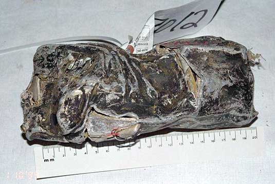
The casing or protective cover of the installed SAI was extensively deformed; the rear of the casing was pushed forward and downward to the right (as viewed from the front), causing the casing to fold over four or five times on itself.
The light plate that held the integral lamps across the top of the indicator was displaced and partially missing. The remaining piece of light plate was still attached to the indicator by the two lead wires. No part of the integral lamps remained. The failure warning flag and the quick erection knob (normally located at the lower right corner) were missing. Although most of the electromagnet that activated the failure warning flag was not recovered, a piece of the electromagnet remained attached to the upper left corner of the frame. The aircraft symbol was not recovered.
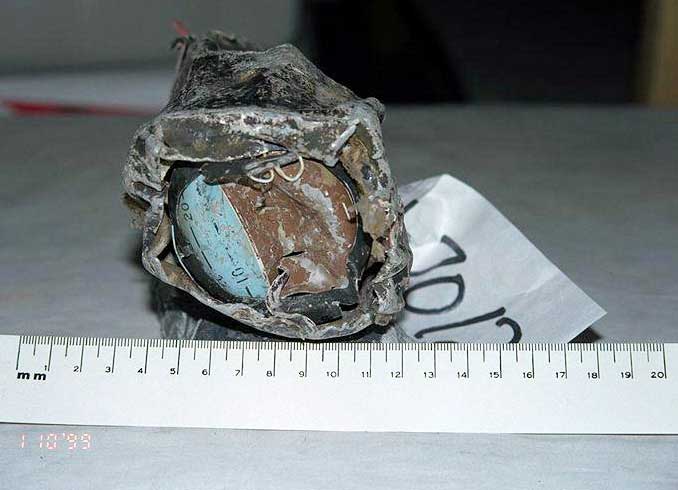
The spherical display drum was captured in place by the deformed surrounding frame.
The aircraft attitude captured at the time of impact was estimated to be 110 degrees right bank and 20 degrees pitch down. The drum exhibited an indent between the zero-degree pitch line and the 45-degree down pitch line.
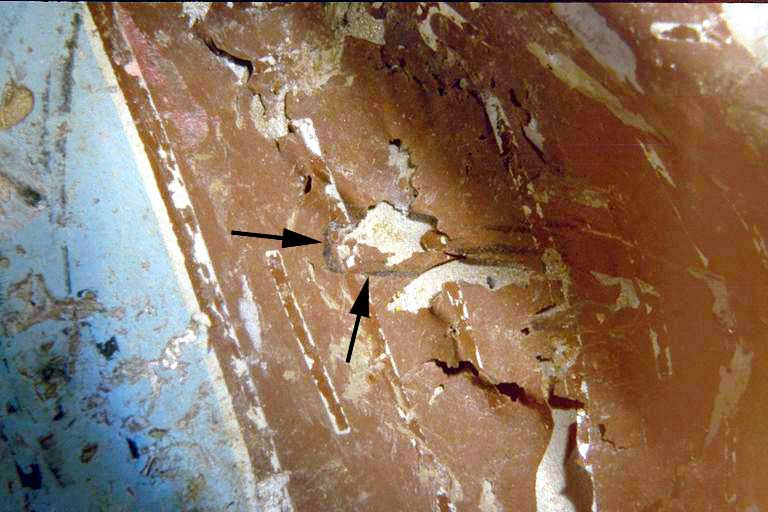
The spherical display drum exhibited a distinct red imprint, measuring approximately 9 mm in length and 3 mm in width with a distinct rounded end, in the upper left quadrant along the zero-degree pitch line graduation.
The imprint was similar in shape and colour to the original fluorescent gyro warning flag. The red imprint was oriented upward toward the left corner where the warning flag arm is attached to an electromagnet. The distance from the rounded tip of the red imprint to the remains of electromagnet measured 32 mm. According to information supplied by Sextant, the overall length of the flag arm, including the flag, was 32.2 ± 0.3 mm. The dimensions of the flag are 13.8 mm by 4.5 mm.
The brown area of the deformed spherical drum exhibited a series of distinct, black imprints.
The end of the imprint closest to the zero-degree pitch line had a distinctive rectangular shape measuring 1.5 mm in width. In total, the imprints measured approximately 25 mm in length. According to Sextant, the aircraft symbol (34 mm), including the support arm (16 mm), was approximately 50 mm long and 1.5 mm wide. It is attached to the right side of the casing.
The drum also exhibited a series of circumferential black imprints that matched the shape of the roll dial. These black imprints extended from the 5-degree up graduation on the left to the 65-degree down graduation on the right. The roll index was positioned on the left of the drum approximately 110 degrees from the vertical. The blue area on the drum to the right of the roll index exhibited a small, black smear that was approximately the same width as the roll index support arm.
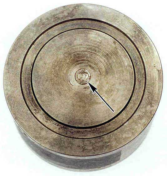
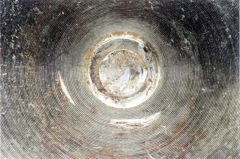
The spherical drum was removed from the indicator. The surface of the drum directly opposite the in-view surface exhibited a distinct circle of imprints, with an indentation in the centre. All of the imprints were distinct.
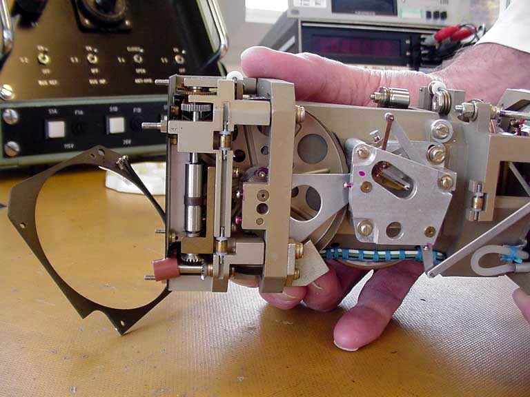
The gyro rotor housing was partially protruding through the side of the casing.
The rotor housing cover was held in place by one of the remaining four screws. The housing exhibited extensive damage, including broken and missing pieces.
The cupric nickel rotor had a light cover of corrosion products. The machined rotor mass consisted of a 2-inch cylinder measuring approximately 1 inch in width with a single bevelled edge. One end of the shaft that supports the rotor had failed. The fractured shaft surface exhibited evidence of a torsional overload failure with extensive surface over-rub. The rotor exhibited comet-like gouges adjacent to both the straight and bevelled edges of the mass. The straight edge adjacent to the cover exhibited three distinct gouges over a circumferential distance of 45 mm. Each of the gouges was located 2 mm from the edge.
Two additional gouges adjacent to the bevelled edge had a melted appearance, unlike the anticipated mechanical damage anticipated to occur at the time of impact. The recovered rotor from the spare SAI also exhibited similar gouges on the rotor surface. According to Sextant, these gouges are caused during the balancing process of the rotor during manufacture. The interior of the rotor mass housing exhibited a number of areas of light scoring and rub contact, many of which bear the characteristic imprint of the machining pattern of the outer diameter of the rotor mass. The housing was machined from a solid block of aluminum alloy and exhibited machine tool markings that are visible under the aluminum paint on both the inner and outer surfaces. These tool markings, however, are much finer than those on the rotor mass surface and the two patterns are easily differentiated.
The wiring in the general area of the SAI wire routing exhibited fire and heat damage. An 11-inch length of wire B201-166-24 exhibited soot damage but no arcing. Four 24 AWG wires exhibited arcing and melting damage. Only one of these wires was positively identified as the fire detector loop A Engine 2 wire.
Determination
The aircraft attitude captured upon impact with the water was estimated to be 110 degrees right bank and 20 degrees pitch down. The capture of the drum and roll index by the surrounding frame and the lack of any evidence indicating that the drum or roll index had moved during or following the impact support this determination.
The fractured surface of the rotor shaft exhibited evidence of a torsional overload failure. The extensive surface over-rub exhibited on the shaft is consistent with continued rotation following separation. The comet-like gouges on the rotor mass adjacent to both the straight and bevelled edges are also consistent with continued rotation of the gyro rotor mass at the time of impact. The actual rotational speed, however, could not be estimated.
The Engine 2 FADEC recorded the last airspeed and altitude to be 228 knots at 1 800 feet asl. At this speed, the SAI would have been crushed in the order of 50 msec; the flag would not have had sufficient time to move from behind the mask to the full in-view position at the time of impact. Since the warning flag was captured in the full in-view position, it was determined that the flag had moved to this position prior to impact. The location of the red imprint on the drum further supports the determination that the warning flag was in full view prior to impact.
Based on the appearance and position of the imprints on the brown area of the deformed spherical drum, it was determined that the imprints were made by the fixed aircraft symbol at the time of impact. It was also determined that the circumferential black imprints that matched the shape of the roll dial resulted from the roll dial being forced into the drum. The marks on the blue area of the drum are consistent with the displacement of the roll index/roll arm further to the left following its initial contact with the surface of the drum.
It was determined that the circle of imprints on the surface of the drum resulted from contact with the bell-shaped forward pitch gear wheel teeth. The indentation in the centre of the gear teeth imprints was consistent with contact with the centre of the gear wheel, which was also forced into the drum. Based on the distinct appearance of the imprints, it was determined that the spherical drum was captured at this position at the time of impact.
In order to determine a more precise pitch attitude, the spherical drum from the spare indicator was removed. The roll dial from the installed SAI was placed overtop the spare drum. The left side of the roll dial aligned at 5 degrees up, and a pitch attitude of 20 degrees nose down was estimated at the mid-point of the roll dial. The installed SAI was also compared to an intact indicator on which the warning flag was in view. The results of this comparison supported the determination that the warning flag was in full view at the time of impact.
Although it was determined that the warning flag was in view at the time of impact, the time at which power was lost to the SAI could not be determined. Although the gyro was rotating with high rotational energy at the time of impact, it could not be conclusively shown that the captured attitude represented the actual aircraft attitude at the time of impact.
Standby airspeed indicator/altimeter
Description
The standby airspeed indicator/altimeter was manufactured by Smith Industries Aerospace, PN WL10AMS5, SN AF768. It was installed on 3 July 1997.
Examination
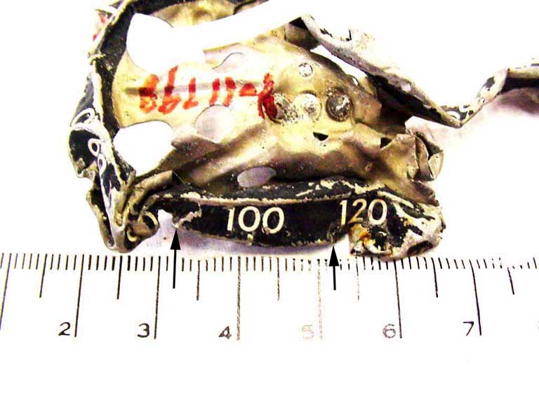
The airspeed dial face was the only part of the standby airspeed/altimeter that was recovered. The dial face, an aluminum circular drum, was extensively distorted. The airspeed dial face exhibited two indentations approximately 20 mm apart located at the 80 knots and 120 knots graduations.
Determination
Based on a comparison of the airspeed dial face and an intact airspeed indicator, it was determined that the drum passed directly in front of two support posts 20 mm apart.
By aligning the airspeed dial drum so that the 80 knots and 120 knots graduations aligned with each support, the 300 knot graduation was placed at the airspeed index mark.
Standby instrument lighting
Description
The same electrical circuit powers the SAI and the standby airspeed indicator/altimeter integral lights.
Under normal conditions, power originates from the 115 V , AC-1 phase B CB B-523 referred to as "MAIN AND PED INSTR PNL LTG," on the lower main CB panel at position A-13. The wire is routed from the CB to plug/receptacle P1/R5-490 in the lower main CB panel. From R5-490, the wire is routed into the avionics compartment to R5/P1-433. The wire is routed from P1-433 to R5/P1-318 in the captain's console. From R5-318 the wire is routed to terminal HV in the main instrument light controller in the left console. This wire powers the controller. A second wire extends from terminal HV to the standby instruments lights R2-211 relay. This relay is powered as long as power is supplied by the 115 V AC-1 CB A-13.
The voltage in the light controller is stepped down by a transformer and feeds CB B1-532 mounted on the P1 panel. From this CB, the wire stays within the left console and is routed to terminal strip S3-785. A wire is routed from S3-785 to the normally open contact A1 of relay R2-211. From R2-211 common contact A2, this wire is routed to R5/P1-337 on the captain's console. The wire is routed from P1-337 to terminal strip S3-866 where it splits and powers both of the standby indicator lights.
If the power is lost from the 115 V AC-1 Bus or if the CB A-13 trips, the lights are powered by the left emergency 115 V AC bus through CB B1-399, "STBY HORIZON ALTIM LTS BACK-UP," on the overhead CB panel at position C-1. The wire from CB C-1 is routed to the overhead switch panel P1/R5-327 above the lower avionics CB panel over the observer's station. The wire is routed from R5-327 into the avionics compartment P1/R5-414 on the aux rack. From R5-414, the wire is routed to P1/R5-318 on the captain's console. The wire is routed from R5-318 to one side of a step-down transformer, T1-189. The wire from the other side of the transformer is routed to the normally closed contact A3 of relay R2-211. The left emergency 115 V AC bus will automatically supply power to the standby lights in the event of a loss of power to R2-211.
The normal power routing to the standby instrument lights is located below the floor. The lower CB panel is located on the aft cockpit wall.
Examination
Because the wire routing is not located in an area of fire damage, there is no reason to suspect a loss of power to the integral lights.
Determination
The warning flag was in view prior to impact, and was most likely illuminated by the integral light. The light should have been visible unless the density of the smoke obscured the instrument.
Standby compass lighting
Description
The standby compass is located at the top of the windshield on the left side of the centre post. The compass must be pulled down to be viewed. The compass is illuminated by selecting the STBY COMP switch located on the overhead light control panel almost directly above the compass. Selecting this switch supplies power from the 28 V DC-1 CB B1-736 located on the lower main CB panel at position D-13.
Wire B114-13-22 is routed via wire run AFW from the CB to P1-497/R5-497 in the lower main CB panel. From R5-497, wire B102-508-22 is routed via wire run AAC to R5/P1-424 in the overhead disconnect switch panel above the observer's station. Wire B203-46-22 is then routed via wire runs AMJ and AMK into the overhead switch panel to terminal strip S3-613, then to R5/P1-204 (also in the overhead switch panel), and finally to pin 9 of the STBY COMP switch. When the STBY COMP switch is selected, pin 11 supplies power back through PI-204 and terminal strip S3-613 to the light in the compass.
Examination
Parts of the wire routing of the standby compass lighting are routed through areas of heat damage, namely, behind the avionics CB panel near the overhead switch panel.
Determination
It could not be determined whether the light in the standby compass was operational at the time of impact.
