Associated links (A98H0003)
-
Table of contents
Structures
Empennage
The stabilizers, elevators, and rudder from HB-IWF were examined to document the fracture and deformation patterns and, if possible, determine the aircraft attitude at the time of impact.
This process was limited to those pieces greater than approximately four feet long. These larger pieces were expected to provide the clearest patterns showing the deformation of the structure as a whole. During the break-up sequence, localized buckling may have caused deformation in smaller pieces that is contrary to the deformation of the overall structure, which would be misleading. Since the salvage operation was thorough, especially salvage of the larger pieces, it is probable that most of the gaps in the reconstruction represent parts that had broken apart into smaller pieces.
Horizontal stabilizers and elevators examination
Pieces of structure that were examined included pieces of elevator in the vicinity of hinge attachment fittings, pieces of stabilizer skin, operating bulkheads, and a length of front spar.
The operating bulkheads are located at the innermost ends of the horizontal stabilizers.
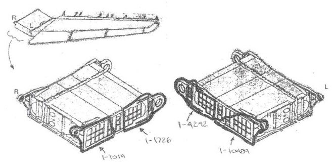
The two bulkheads were fractured, and both bulkheads were fractured at similar locations. The rear connection point of each bulkhead was still attached to a piece of aft fuselage structure, the piece of fuselage structure attached to the right bulkhead being the larger of the two.
The single large piece of front spar that was recovered came from the inboard end of the left stabilizer. It had been bent aft. There was no conclusive evidence of any up/down bending deformation, or of any nose-up/nose-down twisting to this section of spar. The large pieces of elevator that were recovered were all located at hinge fittings. Each piece included the hinge fitting and the short length of the rear spar to which the hinge fitting was attached. Note the corresponding locations on the left and right elevators and their similar appearance.
No conclusive deformation or fracture patterns were observed in any of the elevator pieces that would indicate whether they had separated upward or downward, or that would suggest the position of the elevator at the time of impact.
A large piece of the torsion box at the inboard aft end of the left stabilizer was still intact, with its upper and lower skins still attached. The lower skin was still attached to the operating bulkhead, but the upper skin had separated. No conclusive deformation or fracture patterns were observed in any of the skin panels that would indicate whether they had separated upward or downward, or whether they had twisted nose-up or nose-down. The ribs were bent outboard.
Horizontal stabilizers and elevators determination
The general damage pattern between the left and right stabilizers showed significant symmetry.
- The operating bulkheads broke at similar locations, and the rear of each bulkhead was still attached to a piece of aft fuselage structure. Pieces of stabilizer skin were still attached to the operating bulkheads.
- Large pieces of stabilizer skin, similar in appearance, were found in corresponding locations on the left and right sides.
- All that remained of both elevators were similarly sized sections located at the hinges; these hinges were still attached to similar short lengths of the rear spar.
Despite the overall symmetry, the left stabilizer showed less severe damage than did the right stabilizer.
- The torque box at the aft inboard end of the left stabilizer was still intact as a single unit.
- The single large piece of front spar that was recovered came from the left side.
The left main spar was bent aft, which is consistent with the stabilizer having been pushed aft by impact forces.
The ribs in the surviving portion of the wing box in the left stabilizer had been bent outboard. Owing to the sweep-back angle of the stabilizer, and the fact that the ribs are perpendicular to the leading edge, outboard bending of the ribs is consistent with impact forces pushing the stabilizer toward the rear.
No conclusive deformation or fracture patterns were observed that would indicate whether the stabilizers had separated upward or downward, or with nose-up or nose-down twist.
Vertical stabilizer and rudder examination
The examination was limited to those pieces greater than approximately four feet in length, and located above the engine nacelle. Pieces examined were limited to pieces of the rudder, since no large pieces of the stabilizer were recovered. The rudder is constructed as four separate pieces: upper forward, upper aft, lower forward, and lower aft.
The lower aft rudder was intact and relatively undamaged. The upper aft rudder was also intact, but was missing its uppermost quarter. The two forward rudders were severely damaged, and the upper forward rudder was missing its uppermost half. The leading edges were indented, and this damage favoured the left side.
Vertical stabilizer and rudder determination
The aft rudders were still relatively intact; the forward rudders were severely damaged and no large pieces were recovered from the vertical stabilizer ahead of the rudders. This is consistent with impact from the front.
The damage to the leading edge of the lower rear rudder favoured the left side, which suggests that the rudder was to the left at the time of impact. However, since the rudder is located at the rear of the aircraft, this impact would have occurred late in the accident sequence and does not necessarily indicate the rudder position just before the aircraft struck the water.
No conclusive deformation or fracture patterns were observed in any of the rudder pieces that would indicate whether they had separated to the right or left, or whether they had twisted.
Empennage overall determination
The deformation and fragmentation damage to the two horizontal stabilizers was almost symmetrical, although the left stabilizer was slightly less damaged. This suggests that the impact was relatively symmetrical, but favoured the right side.
Although there was physical evidence showing impact forces toward the rear, there were no conclusive deformation or fracture patterns that would indicate whether the horizontal stabilizer had separated upward or downward, with a nose-up or nose-down twist, nor was there evidence to indicate whether the vertical stabilizer had separated to the right or to the left. There was insufficient evidence to estimate the angles of bank, pitch, or yaw at the time of impact.
Wings
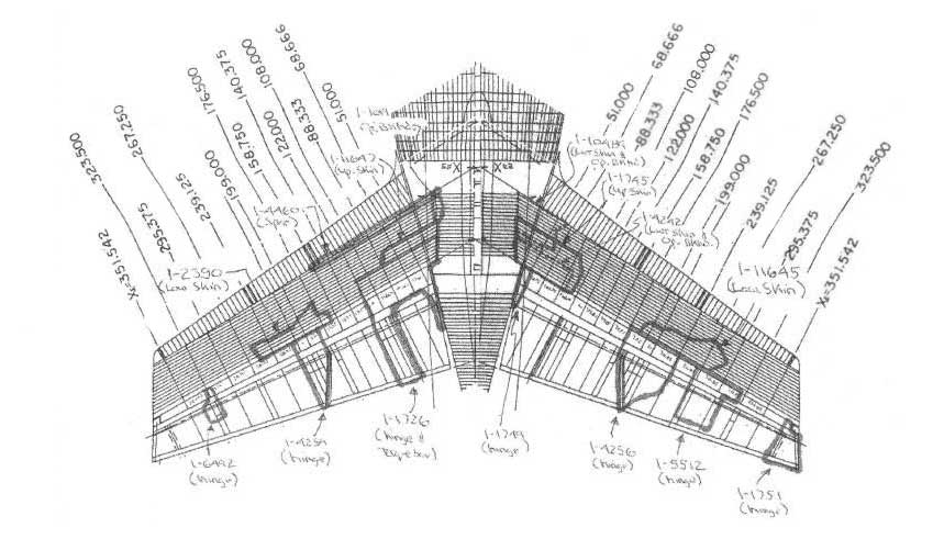
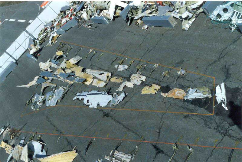
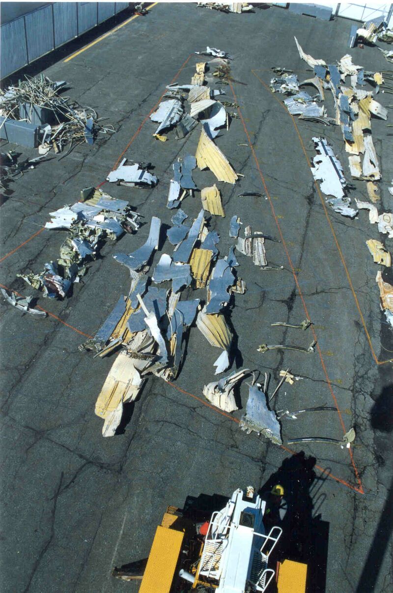
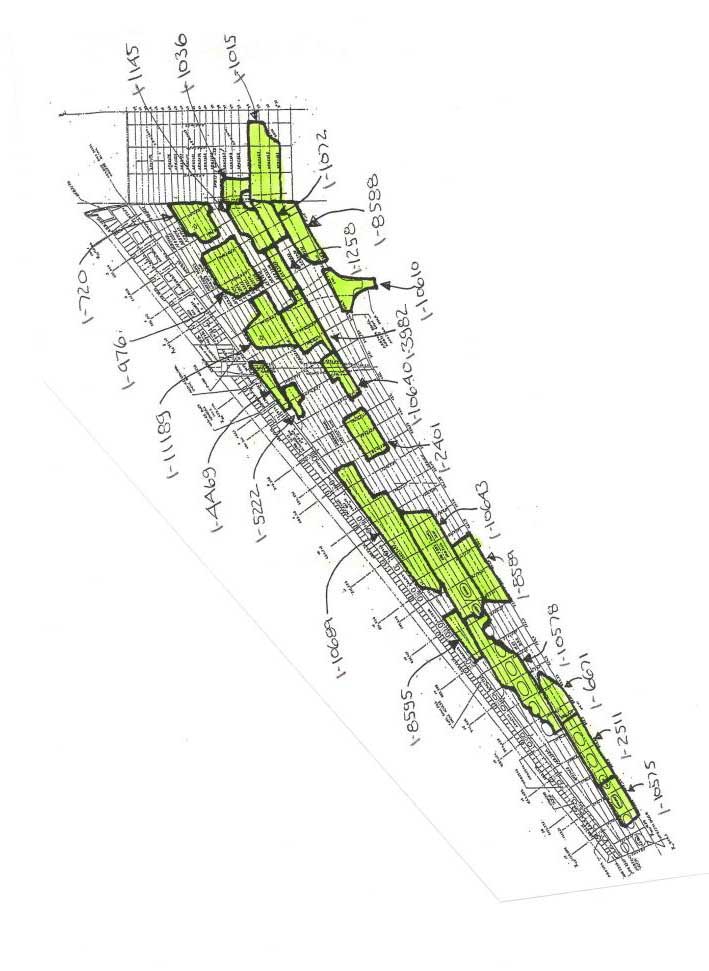
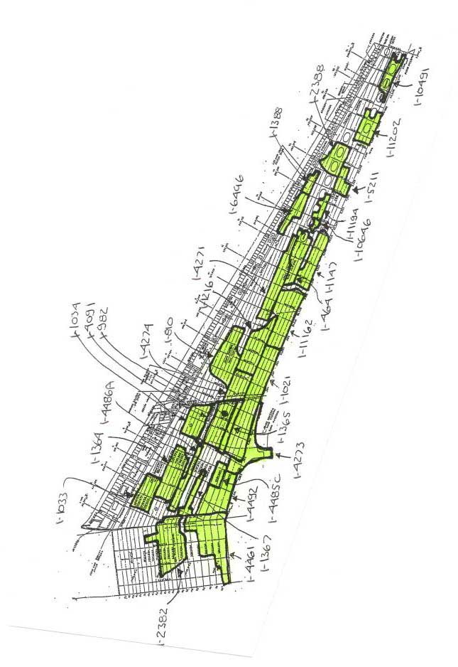
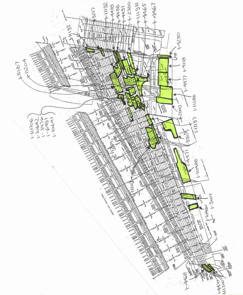
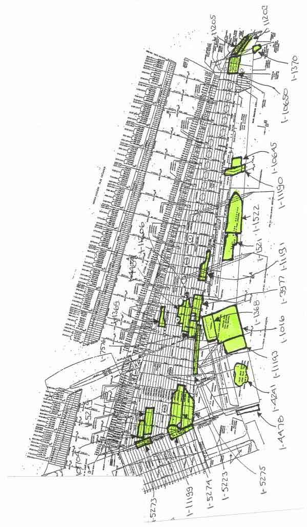
Pieces of wing structure from HB-IWF were individually identified and then laid out on the ground in their relative original positions. The aim was to document the recovered wing structure and, if possible, identify fracture and deformation patterns that could be used to determine the aircraft attitude at the time of impact.
This process was limited to those pieces greater than approximately four feet in length, as the larger pieces would provide the clearest patterns showing the deformation of the wing as a whole. During the break-up sequence, certain areas may have been subjected to localized buckling; therefore, smaller pieces might show deformations contrary to those of the overall wing.
Wing skin examination
Left versus right
The left and right wings showed similar fragmentation. At the inboard ends, the right lower wing appears to have a slightly greater number of large skin pieces than does the left wing. At the outboard ends, the left wing appears to have slightly larger pieces.
Top versus bottom
The upper skins were more severely fragmented than were the lower skins. The upper wing skins were manufactured from 7150-T6151 aluminum, which has a lower fracture toughness than the 2024-T351 aluminum from which the lower skins were manufactured. The upper skins were made of a thinner material than were the lower skins.
Wing skin bending deformation
Top versus bottom
The majority of the lower skins were bent concave down, whereas the majority of the upper skins were bent concave up.
Left versus right
The intensity of the bending deformation appears to be slightly greater on the left wing. There were several severely bent pieces from the left wing; the right wing pieces did not show the same extent of bending.
Skin torsional deformation
Each skin piece was examined to determine whether its outboard end tended to be twisted nose-up or nose-down with respect to the inboard end.
Top versus bottom
The torsional deformation was much easier to observe on the lower skins, which tended to be larger and were made of a more ductile material.
Left versus right
The left lower skin showed unique nose-up torsion; the right lower skin showed the torsion to be evenly distributed between nose-up and nose-down.
Wing skin determination
Since the salvage operation was thorough, especially with respect to large pieces, it is probable that most of the gaps in the reconstruction represent parts that had broken apart into pieces smaller than those being considered.
The upper wing skins were more fragmented than the lower skins since the upper skins were of a thinner gauge and were manufactured using a material with a lower fracture toughness. While the right wing tended to be fragmented in slightly larger pieces, the difference in fragmentation between the left and right wings was not significant. This could suggest that the left wing was subjected to slightly greater impact energy; however, the differences are so small and so few that this may not be significant.
Spanwise bending of the overall wing during impact would have caused the upper and lower skins to bend in generally the same direction, with a few possible discrepancies owing to localized buckling. However, the lower skins are bent concave down while the upper skins are bent concave up, which is not consistent with the bending of the overall wing at the time of impact. This particular mode of failure is likely the result of a hydrodynamic effect (of wing fuel or of seawater) that caused the wing to burst. Although the impact attitude would nevertheless have resulted in some bending of the wing skins, the hydrodynamic effect was so much greater that it masked the effect of the attitude. The severity of wing skin bending was slightly greater on the left than on the right. Although this could suggest that the phenomenon responsible for bursting the wings was more severe on the left, the difference is so subtle that it may not be significant.
It was not determined whether the wing skin torsion deformation was caused mostly by impact attitude or by the hydrodynamic effect that burst the wing. Since the bursting effect was of such great magnitude that it overwhelmed the attitude effect in the bending mode, it probably also did so in the torsion mode. Therefore, the direction of the wing torsion is not considered to be a reliable indicator of the aircraft angle of attack at the time of impact. In the left lower wing the skin panels tend to be twisted in the same direction, whereas in the right lower wing they twist in both directions. This suggests that while the torsion in the left wing was the result of a single phenomenon, the torsion in the right wing had more than one cause.
Stringer and shear clip damage
Damage to the stringers and shear clips of both wings was compared. Damage tended to be slightly greater on the left. However, since the differences between the sides are subtle, are open to considerable interpretation, and involve a small number of pieces, they may not be significant.
The most common type of stringer damage in both wings was the fracture and separation of the vertical flange from the base of the stringer. Another type of stringer damage observed was where the stringers had been torn away completely from the wing skin. This type of damage was slightly more prevalent in the left wing than in the right wing. The final type of stringer damage observed was where the vertical flange was still partially attached to the base of the stringer. This type of damage was slightly more prevalent in the right wing than in the left wing.
The most common form of failure in the left wing was the tearing away of the shear clips. In the right wing, many shear clips were still relatively intact.
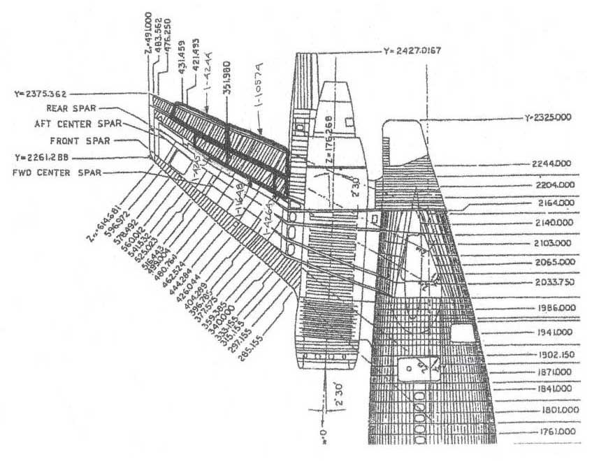
Wing spars examination and determination
Forward versus rear spars
None of the large wing pieces examined were from the forward spar; the only large pieces were from the rear spar.
Left versus right
The wing layout process included only the larger pieces of rear spar structure. Four pieces of the left spar and seven pieces of the right spar were recovered.
Deformation
Most of the spar pieces showed either deformation with the concave side toward the front or sinusoidal buckling deformation.
Determination
Since the front spar is thinner and taller than the rear spar, has holes in it for the slat tracks, and is located nearer the front (where it would absorb more impact energy), it is not surprising that the only surviving large spar pieces were from the rear spar. During impact, the wings would have been forced aft. This would have put a compression load in the rear spar, which could explain the sinusoidal curvature of many pieces. The appearance of the upper and lower wing skins suggests that the wing burst from internal pressures. This phenomenon may also explain why more spar pieces were found to have their concave face toward the front than toward the rear. The smaller number of large spar pieces recovered from the left wing suggests that the left wing was subjected to a greater impact energy, but since only a few large pieces were recovered, this may not be significant.
Wing ribs and bulkheads examination and determination
Left versus right
The wing layout process involved only larger pieces of rib and bulkhead structure. One piece from the left wing and four pieces from the right wing were recovered.
Deformation
Most of the pieces showed deformation with the concave side toward the right or sinusoidal buckling.
Determination
The smaller number of large rib pieces recovered from the left wing suggests that the left wing was subjected to greater impact energy, but since only a few large pieces were recovered, this may not be significant. There appeared to be a tendency for the rib deformation to favour the concave side to the right. In any case, it was not determined whether the curvature was caused by the fuel or seawater forces.
Slat tracks examination and determination
Most of the tracks on the right wing were bent toward the right, whereas those on the left wing were about evenly divided between those bent left and those bent right.
The slat tracks are normal to the wing leading edges, and the wing leading edges are swept back 35 degrees. Owing to this geometry, unless the aircraft had struck the water with a significant yaw angle, all the slat tracks on both wings would be expected to have been bent outboard. Almost all the tracks on the right wing were bent outboard, as expected. However, on the left wing, the tracks at the inboard end were bent outboard as expected, but those at the outboard end were bent inboard. One possible explanation for this is that, since there are two distinct modes of failure on the left wing, the left wing may have struck the water later in the accident sequence.
Pylon attachment fittings examination and determination
There is one such fitting associated with each engine. Both fittings were bent aft. The left fitting was bent further aft, but the spar at the right fitting is slightly more damaged. Seen from above, both fittings show clockwise torsional deformation.
The fact that these fittings were bent aft is consistent with the engines having been forced nose-down during the impact. The left fitting is bent aft to a much greater extent than is the right fitting, which suggests that it received a greater impact force. However, the piece of the front spar at the top end of the right fitting was more damaged than was the left one. This suggests that the right fitting experienced less bending, not because it experienced a smaller force, but simply because it lost stiffness at its upper end owing to spar fracture. The engines are normally toed inboard 2 degrees. If the aircraft had struck the water with zero yaw, the engines might be expected to be forced nose-inboard, twisting both pylon attachment fittings inboard. Both fittings showed clockwise deformation (viewed from above), which means that the nose of each engine was pushed to the right upon impact. This suggests a nose-right yaw of greater than 2 degrees at the time of impact.
The absence of any significant difference in the damage between the two wings suggests that there were no significant differences in the magnitudes and orientations of the impact forces that acted upon them. This, in turn, suggests a nearly symmetrical impact.
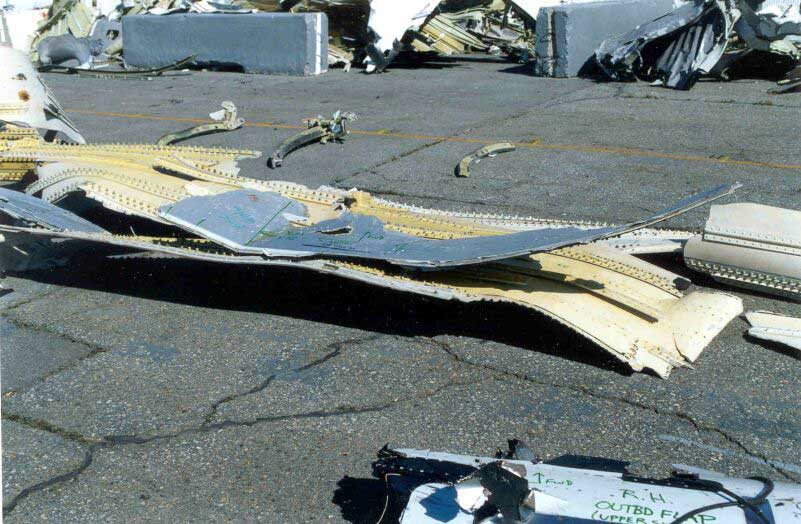
Control surfaces
The control surfaces were examined for deformation and damage patterns with the following results:
- No significant differences were observed between the left and right wings in the size or quantity of the pieces.
- The left outboard flap had a vane track at its leading edge that was bent inboard.
- The right wing fuel dump pipe was bent outboard.
- The right inboard flap had a vane track at its leading edge that was bent inboard.
Wingtips
Winglets
There were no significant differences between the left and right winglets in the damage they sustained. The outboard-most region of the right wing was still relatively intact, with the upper and lower skins still attached to the internal structure.
Wing overall determination
The deformation and fragmentation patterns did not vary significantly between the two wings. There were no significant differences in the magnitudes and orientations of the impact forces that acted upon them, which suggests a nearly symmetrical impact.
Close examination of skin bending and torsion, slat track bending, and damage to the stringers, shear clips, spars, ribs, and pylon attachment fittings revealed subtle differences that suggest the left wing may have sustained greater damage, and that the aircraft may have been yawed nose-right at the time of impact. However, the differences were so subtle, and involved so few pieces, they were inconclusive. There was no conclusive evidence from which to estimate the angles of bank or pitch at the time of impact with the water.
Cabin outflow valve doors
Cabin outflow valve doors examination
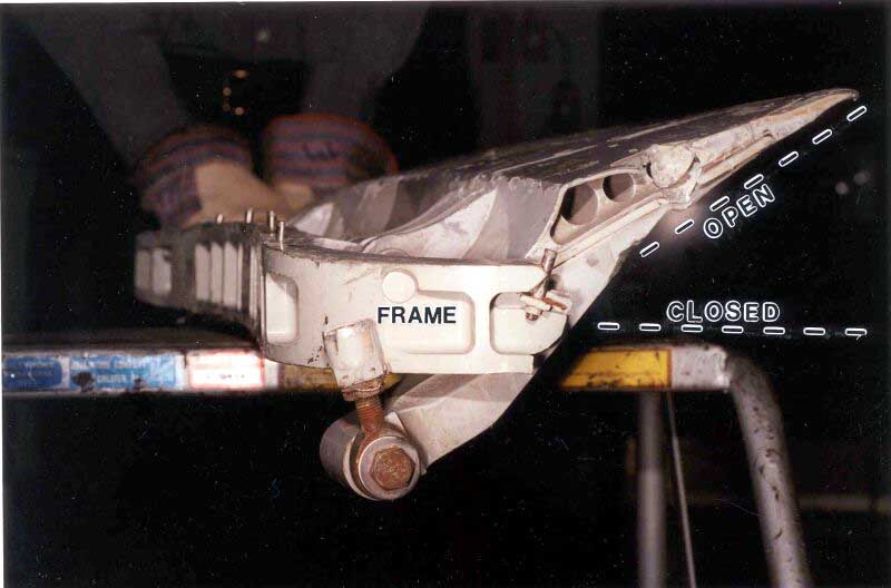
The doors from the lower forward fuselage cabin outflow valve were recovered. They were submitted for engineering examination to determine whether they were open or closed at the time of impact.
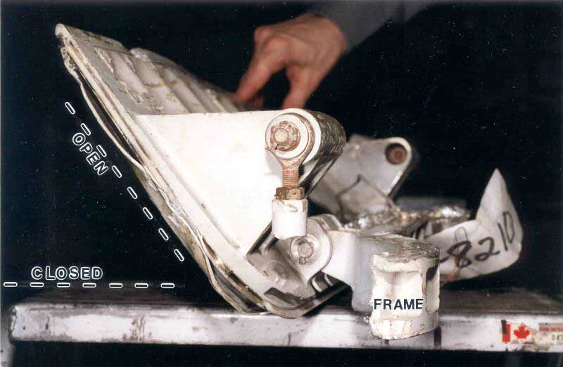
The entire door frame was recovered. The forward door is hinged along its forward edge, and opens by swinging outboard, away from the fuselage. The aft door is hinged along its aft edge, and opens by swinging inboard, into the left tunnel area. The doors are connected by a mechanical linkage, so they move in unison.
Generally, the door frame structure was bent away from the door, so it did not capture the door in its position at impact. Only at one location, along the forward edge of the forward door, was the door frame deformed toward the door. The forward door was trapped in an open position by the deformed frame (i.e., it was swung outboard).
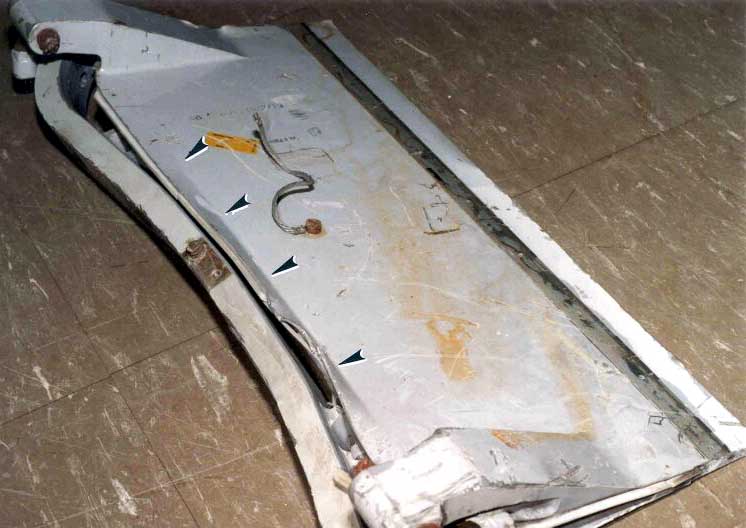
There is a very smooth mark visible along the length of the frame, probably the result of long-term wear. Although the door frame is deformed aft, the leading edge of the door itself has not been pushed aft by this frame. Rather, the leading edge of the door is bent inboard.
The aft door was not trapped by frame deformation, and was still free to swing open and closed. Damage near the lower hinge was probably caused when the hinge lug was bent. When the door is open (i.e., swung inboard), damage to the door's portion of the hinge lug aligns with damage to the frame's portion of the hinge lug. However, when the door is closed, the two damaged areas no longer align.

None of the many scratches and gouges on the surfaces of the doors are continuous across the both doors. There were no marks visible on the frame or on the door that were consistent with an impact of the door against the frame.

Uniform light soot was observed along the hinge line of the forward door. This soot was predominantly concentrated on the upper half of the door in the white painted area. A corresponding deposit of light soot was observed on the exterior skin of the upper half of the aft door. Localized deposits of moderate soot were also observed in depressions in damaged areas of the door. It is believed that the moderate soot deposits are representative of the exterior condition of the door prior to impact. The depressed areas would have preserved more soot deposits than other exposed areas. The inside surfaces of both doors also exhibited light soot deposits.
Cabin outflow valve doors determination
Not enough of the door actuator mechanism was identified to indicate the position of the doors at the time of impact.
The forward door was trapped in the open position by the deformation of the adjacent door frame. This suggests that the door was open when the frame became deformed. The forward door frame was deformed aft. Had the forward door been closed when this frame deformation occurred, the front edge of the forward door would have been crushed aft. Instead, this edge was pushed inboard. The front edge of this door could only have been pushed inboard if the door had been open when the adjacent frame was deformed. After the frame had been deformed, the door was then forced closed against the deformed frame, causing the edge of the door to bend inboard. This suggests that the door was open when the frame was deformed.
The observed soot pattern on both doors is consistent with the doors being open at the time the soot was accumulated. Little if any soot would be expected to have been deposited on the exterior skin of the forward door, since the exterior skin faces directly into the airstream. In contrast, the exterior surface of the aft door would have been exposed to smoke being expelled from the opening of the outflow valve.
The only evidence found to suggest the position of the aft door at the time of impact was a mark on the lower hinge made when the hinge lugs were bent. This damage only lines up when the door is open, which suggests that the door was open when the damage occurred.
Both doors appear to have been open in their appropriate directions when witness marks were created by the deformation of the frame and hinges. This suggests that the linkage between the two doors was still intact when those witness marks were created. Since the two doors were found apart, without the linkage mechanism, it is likely that the witness marks were created early in the accident sequence. The earlier the witness marks were created, the more likely it is that they are representative of the door position at the time of impact.
Among all the scratches, gouges, and dents on the surfaces and edges of the doors, not a single mark is continuous across both. Had the doors been closed when the marks were made, some marks would be continuous across the doors. This suggests that the doors were not closed when the marks were made.
Based on the damage patterns observed on the doors, it was determined that the doors were open at the time of impact.
Cockpit sliding clearview windows
Description
Each pilot is provided with a sliding clearview window. These are plug type windows that rest against a flange all around the perimeter of the sill. This flange reacts to pressurization loads and keeps the windows from being displaced outward. Along the forward edge of each window there are three blocks, which trap the forward edge of the window against the sill flange and stop the window from being displaced inward. Along the aft edge of each window, there are three moveable latches connected to a locking lever on the lower edge of the window. When these latches are extended, they trap the aft edge of the window against the sill flange. When these latches are retracted, the aft edge of the window is free to move inward.
A crank and chain mechanism on the bulkhead below the window sill moves the window. To open the window, the locking mechanism is first released. This action releases the latches on the aft edge of the window, but does not move the window. By turning the hand crank the aft edge of the window is pulled inboard enough to clear the sill, whereupon it slides aft. When the aircraft is pressurized, the outward force on the window is so great that turning the hand crank will not open the window, although it can still be unlocked. The unlocked window would not affect the airflow in the cockpit as long as it remained unopened.
First officer's window examination
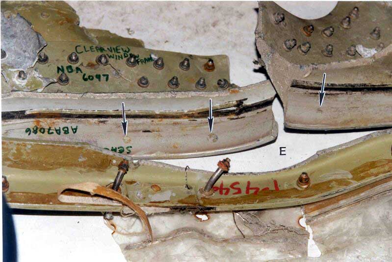
The area of metal normally in contact with the latch was plastically deformed. The third latch plate, labelled "C," was missing, and the rivets that held it had sheared away. The damage at all three latch locations was consistent with the window having been forced inboard. Both the window and sill fractured at the same location and have the same bend at location "E."
Indentations in the sill, at locations "E," correspond to the position and pitch of the fasteners used around the perimeter of the window. These indentations penetrate both the paint and the primer, and extend into the metal.
First officer's window determination
Damage to the two upper latch plates is aligned with the position of the latches when they are locked. Furthermore, the damage has the same shape as the ends of the latches. Therefore, the damage to the latch plates was likely caused by the latches. This is consistent with the latches having been locked at the time of impact.
The separation of the third latch plate was consistent with the direction of the damage to the first two. The direction of this damage to all three latch plates is consistent with the window having been forced inboard by the impact.
As the window and sill were fractured and bent at the same locations, they were likely in close contact when fractured. The window and sill are only in close contact when the window is closed, because the first action of the window-opening sequence is to move the window inboard so that it can slide back over the aft sill. The damage is consistent with the window having been closed at the time of impact.
The marks along the sill were consistent with the pitch interval and location of the fasteners around the perimeter of the window. The depth of these marks, which in most instances penetrated both the paint and the primer, and indented the metal, was inconsistent with marks caused by long-term wear, which do not penetrate the paint. These marks are also consistent with the window and sill having been in close contact (and the window closed) at the time of impact.
The physical evidence is consistent with the first officer's sliding clearview window having been closed and locked at the time of impact, and having been pushed inward by impact forces.
Captain's window examination
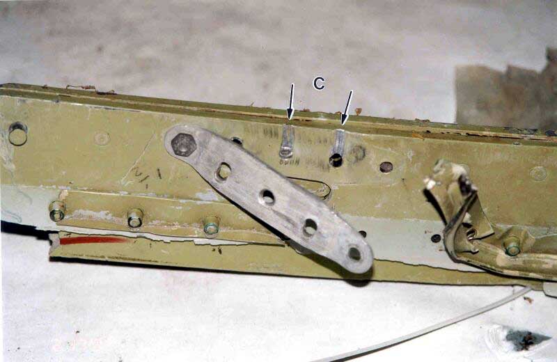
The metal on the two upper latch plates on the aft sill, labelled "A" and "B" has not been deformed as it was on the first officer's window. The lower latch plate on the aft sill "C" and its corresponding latch were still attached to the window structure.

Latch plate
The captain's window latch plate and latch were not plastically deformed.
Linking arm
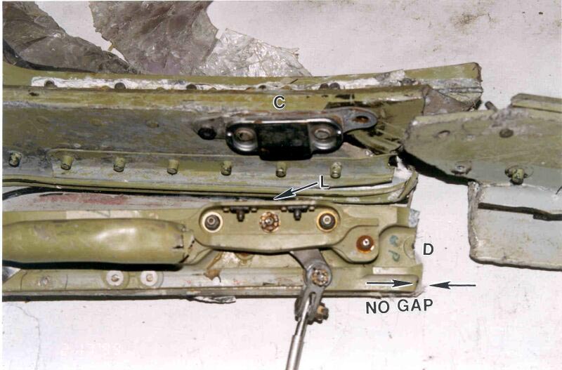
The linking arm, which attaches the latch to the other latches, had fractured. When the latch is in the locked position, this fracture does not align with the fracture in the window and sill. When the latch is in the unlocked position, this fracture aligns with the fracture in the window and sill, at location "D" (see picture of captain's window – lower latch plate above). The arm is trapped and deformed in the retracted position and corresponds to the latch being in the locked position.
Window and sill
At the lower aft corner of the window, both the window and sill fractured at the same locations. At the upper forward corner of the window, the fractures to the window and sill roughly align, but not as closely as at other locations.
Marks on the sill correspond to the position and pitch of the fasteners used around the perimeter of the window. A survey of similar aircraft found that normal wear resulted in fastener marks on the sills, but that these marks never penetrated the surface of the paint. The remainder of the marks, however, penetrate both the paint and the primer, and extend as an indentation into the metal.
Captain's window determination
The three latch plates on the captain's window did not show the same damage caused by the latches as did those on the first officer's window. Although this may be an indication that the window was not locked, it is also possible that the two windows experienced different loads upon impact.
In the vicinity of the lower latch, the sill and window fractured at the same location. If the fracture of the linking arm, which is in the same area, is aligned with the other two fractures, its position corresponds to the window being unlocked. Although this may be an indication that the window was not locked, it is also possible that it is the result of the particular loading experienced during impact.
The telescoping arm, which moves the latch, was jammed in the locked position. Although this may be an indication that the window was locked, it is also possible that, since it is cable actuated, the cable pulled it to the locked position during the break-up sequence. The physical evidence described above is inconclusive regarding whether the captain's window was locked at the time of impact.
At the lower aft corner, the window and sill were fractured at similar locations, which is consistent with the window having been closed. However, there were discrepancies at the upper aft and upper forward corners, where the fractures lined up less precisely. These discrepancies may indicate that the window was slightly open. They may also be the result of the influence of the pivoting joint in the upper aft corner of the window, which could have affected bending forces in the window.
The marks along the sill were consistent with the pitch and location of the fasteners around the perimeter of the window. In most instances these marks penetrated both the paint and the primer, and indented the metal. This is consistent with the marks having been caused by the impact and with the window having been closed at that time.
The physical evidence concerning the position of the captain's sliding clearview window was less conclusive than in the case of the first officer's window. While there was no evidence to indicate that it was locked, it is believed to have been closed.