In-Flight Break-up
Helifor Industries Limited
Boeing Vertol BV-107 II (Helicopter C-GHFT
South Bentinck Arm, British Columbia
The Transportation Safety Board of Canada (TSB) investigated this occurrence for the purpose of advancing transportation safety. It is not the function of the Board to assign fault or determine civil or criminal liability. This report is not created for use in the context of legal, disciplinary or other proceedings. See Ownership and use of content. Masculine pronouns and position titles may be used to signify all genders to comply with the Canadian Transportation Accident Investigation and Safety Board Act (S.C. 1989, c. 3).
Summary
The Boeing Vertol helicopter, model BV-107 II (registration C-GHFT, serial number 402), was engaged in helicopter logging operations in the South Bentinck Arm, 20 nautical miles from Bella Coola, British Columbia. At 1330 Pacific standard time, the helicopter was returning to the log pick-up site when one of the two pilots radioed that the helicopter was vibrating. Moments later, the crew made a second radio transmission indicating that the helicopter was behaving in an unusual manner and that they would be returning to the maintenance base. Approximately 10 seconds later, the helicopter suffered an in-flight break-up and fell to the ground in several sections. Both crew members sustained fatal injuries.
Factual information
The occurrence helicopter was leased to Helifor Industries Limited by Columbia Helicopters Incorporated of Portland, Oregon.
The weather in Bella Coola, about 15 nautical miles (nm) north of the occurrence site, at the time of the accident was as follows: visibility 15 statute miles, overcast cloud at 3500 feet above sea level (asl), and calm winds.
The helicopter wreckage was found distributed over a three-hectare area. These main sections - the cockpit and forward fuselage, the aft fuselage and engine compartment, and the aft pylon and transmission - were all within 150 yards of each other. There was a small post crash fire in the engine compartment that self-extinguished. Numerous smaller pieces were located throughout two identifiable debris fields along the helicopter flight path. These smaller pieces were comprised of sections of the main rotor blades, synchronizing drive shaft segments, drive shaft tunnel, and fuselage.
Following documentation of the accident site, the wreckage was transported to a hangar at the Vancouver International Airport for detailed examination. The engines were transported to Columbia Helicopters Incorporated. in Portland, Oregon, for further examination. Both engines were examined by TSB investigators to the extent possible, and no anomalies were found. There was nothing found to suggest that power loss occurred before the in-flight break-up.
Drive continuity of the forward transmission was confirmed, and no anomalies were found. The red and greenFootnote 1 forward rotor blades remained attached to the rotor hub assembly. The yellow blade had separated at the blade hinge due to ground impact. There was no indication of blade to blade contact or of forward blade contact with the fuselage. Damage to the forward rotor blades was consistent with ground impact.
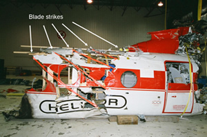
Examination of the aft transmission revealed a fracture at the combining gearbox casing. Continuity of the aft transmission drive was confirmed, and the case fracture was consistent with ground impact forces. The three aft rotor blades exhibited signs of contact with the helicopter fuselage: fuselage paint transfer, scuffing, control cable marks, and spar fractures. There were significant impact marks on the leading edge of the three rotor blades. All aft rotor blade fragments were recovered with the exception of the outboard four feet of the red blade. The majority of the damage to the aft rotor blades was consistent with fuselage contact, with the remaining damage due to ground impact. Partial reconstruction of the fuselage revealed six blade strikes extending from the synchronizing drive shaft tunnel on the roof of the fuselage to the floor of the helicopter (see Figure 1 and Photo 1).
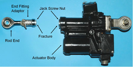
All flight controls were visually examined, and continuity was verified to the extent possible. With one exception, all fractures of the flight control system were consistent with overload due to impact forces. A fracture of the jack screw nut on the longitudinal cyclic trim actuator exhibited signs of fatigue (see Photo 2). The jack screw nut was examined macroscopically and the fracture surface revealed features typical of a progressive failure.
The fracture surface intersected the last thread in the jack screw nut that accommodates the end fitting adaptor. The rod end, which screws into the end fitting adaptor, was found damaged to the extent that the rod end bearing would not move freely. Further examination of the aft pylon and swash-plate area revealed scoring on the underside of the aft rotor head rain shield. This damage was consistent with the rod end coming into contact with the swash plate and rain shield before ground impact.
Speed Trim Actuator Maintenance History
The longitudinal cyclic trim actuator is commonly referred to as the speed trim actuator. The speed trim actuator from the occurrence aircraft (part number 541168-1-1, serial number 115-377) was originally manufactured by AiResearch, which eventually became part of Honeywell International Incorporated. It was recently overhauled by Columbia Helicopters Incorporated and installed on C-GHFT on 05 March 2005. The actuator has an overhaul life of 2000 hours and had accumulated 1409 hours since last overhaul. It had accumulated 20 982 hours since new. During the last overhaul, it was determined that the actuator overran the retract switch. It is not known if this was the cause of the removal or if the overrunning condition was found during the pre-overhaul inspection. Parts replaced during the last overhaul included both the retract and extend limit switches, jack screw nut, and rod end adaptor. The TSB requested the source control documents for the replaced parts, but Columbia Helicopters Incorporated was unable to provide them. Once the speed trim actuator is installed and adjusted in accordance with the Boeing 107 maintenance manual, no further testing or monitoring is required.
Speed Trim Actuator Operation
The speed trim actuator is an electric actuator installed between the aft upper controls and the swash plate to provide limited control of the aft rotor head in the pitch axis. The two primary purposes of the speed trim actuator are to minimize stress on the vertical drive shaft and to maintain a level pitch attitude of the helicopter at higher airspeeds. Pilots control the speed trim actuator from the cockpit by operating a switch on the collective controls. A speed trim indicator, located on the instrument panel, indicates the position of the actuator as a function of airspeed. When flying below 70 knots, the actuator would be fully retracted, and at 100 knots or higher, the actuator would be fully extended. Separation of the speed trim actuator from the swash plate would result in the loss of longitudinal cyclic control of the aft rotor head.
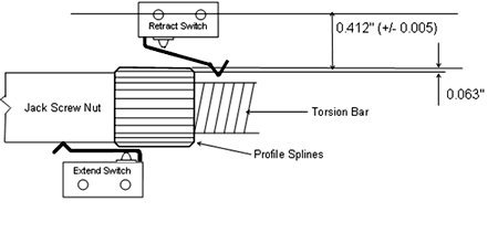
The speed trim actuator incorporates two limit switches, one for retract and the other for extend (see Figure 2). The purpose of these switches is to stop the electric motor at the retract or extend limit of the actuator. The two limit switches are activated by profile splines, which are integral to the jack screw nut. The switches incorporate an arm that rides on the profile splines. When sufficiently compressed, the arm activates a plunger on the switch and interrupts the electricity to the motor.
When airborne, the pilot selects the cyclic trim as a function of airspeed by selecting either CYC FWD (extend) or AFT TRIM (retract) on the collective control. The actuator jack screw nut moves in the selected direction until such time as the limit switch arm rides up the profile spline. In normal operation, the switch would activate before reaching the top of the profile spline and the motor would stop, ending the retract or extend operation.
Speed Trim Actuator Examination
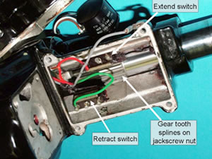
Before disassembly (see Photo 3), the occurrence speed trim actuator was energized to establish the fully retracted and extended positions. These tests confirmed that the extension was in the normal range. In the retract direction, the actuator overran the normal stop, retracting beyond the normal limit. Both switches were then manually tested for electrical on/off function and found to be capable of on/off operation. Further testing revealed that the retract switch arm rode up the maximum height of the profile spline without depressing the switch plunger sufficiently to activate the internal electrical contacts of the switch. For testing purposes, the retract and extend switches were interchanged, and the actuator worked normally. Testing of the occurrence actuator with the limit switches interchanged revealed that the actuator stroke length was correctly adjusted at the time of overhaul, indicating correct adjustment of the switches in the horizontal axis. There is no adjustment available for the switches in the vertical axis - the distance between the switch and the splines.
It was also noted that the retract switch arm had a groove worn where it contacts the profile spline. This wear was measured to be 0.003 inches. Switches from other actuators that had reached overhaul life exhibited wear on the arm, and on one switch, the arm was worn completely though yet continued to operate normally.
The electric motor drives a series of gears, causing the torsion bar to rotate. The torsion bar is inside the jack screw nut. Rotation of the torsion bar causes the jack screw nut to extend or retract. If the retract switch were to fail during retraction, the rod end adapter would eventually contact the face of the torsion bar and act as a mechanical stop. The electric motor would continue to apply force to the torsion bar even after travel had been halted by the mechanical stop. There are no indications to the pilots or maintenance personnel when the actuator limit switches have failed and the jack screw nut is contacting the mechanical stop.
Examination of the torsion bar inside the jack screw nut revealed damage to the keyway in the shaft of the torsion bar. Damage to the keyway is consistent with the motor continuing to drive in the retract direction after it had reached the mechanical stop.
Energy dispersive X-ray analysis (EDX) of the end fitting adapter revealed that it was cadmium plated, but the majority of the cadmium plating was worn away, most likely by contact with the torsion bar. Scanning electron microscope (SEM) examination of the torsion bar face revealed small isolated patches of bright-coloured material, which were analyzed by EDX and found to be cadmium.
Jack Screw Nut Examination
SEM analysis of the jack screw nut revealed that numerous fatigue cracks had initiated at the inner diameter of the nut in the root of the last of five threads (inside actuator body). The cracks had propagated around the entire circumference of the fracture surface, suggesting a symmetrical tension load, an indication that the actuator was not misaligned during installation. The fatigue cracks had propagated toward the outer surface until the final 10 per cent of the material failed in an overload mode.
The internal jack screw thread was a 3/4-20 UNEF-3B,Footnote 2 as specified on the production drawings. The internal thread-root radius of the jack screw nut was roughly 0.001 inches. The thread radius in two exemplar jack screw nuts varied from 0.001 and 0.004 inches.
Fatigue is a process that results in cracking and/or failure of a component subjected to fluctuating or repeated loading. Failure due to fatigue can occur at loads or stresses much below those necessary to cause overload failure of non-fatigued components. Since fatigue failures generally occur at locations of high stress concentration, threaded components are especially vulnerable because of the notch-like conditions at the thread roots. The smaller the thread-root radius, the greater the stress concentration factor.
A review of specifications found that the UNEF thread standard does not specify a minimum allowable thread-root radius. For comparison purposes, the UNJFFootnote 3 thread standard specifies a minimum allowable thread-root radius of 0.0075 inches, the BSWFootnote 4 thread standard specifies a minimum allowable thread-root radius of 0.0069 inches, and the DINFootnote 5 40430 thread standard specifies a root radius of 0.008 inches. Experimental fatigue testing has found that a BSW thread has a stress concentration factor of 3.85. Other testing has found that stress concentration factors can be as low as 3 for UNJF threads and as high as 6 for threads with sharp or flat roots. It is considered that the occurrence thread, with its 0.001-inch thread-root radius, likely had a stress concentration factor of 7.8 or higher.
Hardness testing of the fractured jack screw nut found an average value of 30.26 Rockwell C, which corresponds to an ultimate tensile strength (UTS) of roughly 138 000 psi. Metallurgy of the jack screw nut was consistent with the manufacturer's specifications. The occurrence actuator was installed in a tensile testing machine, with the retract switch disabled to allow the actuator to contact the mechanical stop. A force of 1324 pounds was required to stall the electric motor. Therefore, if the retract limit switch does not activate and the actuator reaches the mechanical stop, a force of 1324 pounds will be applied to the jack screw nut - a force four times greater than generated during normal flight loads.
Actual stress on the jack screw nut was calculated to be approximately 60 000 psi. Generally, for steels with a UTS less than 200 000 psi, the endurance limit will be between 0.35 and 0.60 of the UTS.Footnote 6 The calculated 60 000 psi value represents 0.43 of the actual material's UTS of 138 000 psi. Therefore, the force due solely to reaching the mechanical stop either exceeds or is very close to the endurance limit. It is considered that, when service loads are superimposed on this, the loads would exceed the endurance limit. If cyclic stresses are kept below the endurance limit, a component can have an infinite fatigue life. As soon as the endurance limit is exceeded, fatigue failure is likely.
Limit Switch Examination
The AiResearch illustrated parts catalogue (IPC) for speed trim actuator part number 541168-1-1 specifies the limit switches as part number 529303-1 for the retract switch and USML117 for the extend switch. Part number 529303-1 is an assembly of two USML117 switches piggy-backed together and was installed in helicopters where the main rotor blades folded. Blade fold was a requirement of some military helicopters used in aircraft carrier operations. The occurrence helicopter did not have blade fold and therefore the dual switch assembly was not required. No other differences were noted for the actuator in the IPC that would affect limit switch location or operation.
An exemplar speed trim actuator was obtained for comparison purposes. Data tags on the exemplar actuator indicate that it had been repaired and tested in 1993 and 1999 by Allied Signal, now part of Honeywell International Inc. The extent of the repair is not known. Examination of the exemplar actuator revealed the use of 2LML82E limit switches in both retract and extend positions. Although Honeywell International Inc. approved the use of the 2LML82E switch for use by the Canadian military only, documentation provided to the TSB revealed that the USML117 switch was superseded and changed to a 2LML82E in November 1977. This documentation confirmed the interchangeability of the two switches. This interchangeability was not documented in the speed trim actuator IPC.
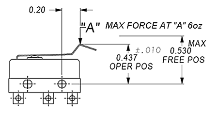
Various examples of 2LML82E and USML117 switches were obtained by the TSB and examined. The results of testing are shown in Table 1. Tests confirmed that the occurrence limit switches did not meet manufacturer's specifications for arm travel (see Figure 3). Using the switch mounting holes as a reference, the arm of the 2LML82E switch should cause the switch to operate at 0.437 ±0.010 inches. The retract switch and the extend switch from the occurrence actuator operated at 0.413 and 0.416 inches respectively - 0.014 and 0.011 inches beyond tolerance. This translates into a greater arm travel for switch activation.
Table 1. Switch Test Data
| Switch Part Number | Force (oz) | Operate Position (in) |
| USML117 - New | 1.6 | 0.439 |
| USML117 - New | 1.8 | 0.439 |
| 2LML82E - New | 2.8 | 0.435 |
| 2LML82E - New | 2.4 | 0.444 |
| 2LML82E - Occurrence retract | 3.4 | 0.413 |
| 2LML82E - Occurrence extend | 2.8 | 0.416 |
| 2LML82E - Manufacturer's specs | max 6.0 | 0.427 to 0.447 |
A new 2LML82E switch and the retract switch from the occurrence actuator were X-rayed to determine if any internal anomalies existed, but no differences were identified. Data sheets for operating characteristics could not be located for the USML117 switches, and it is unknown if the USML117 switches that were tested conformed to manufacturing specifications. However, with the exception of operating force, which was less on the USML117, both the 2LML82E and the USML117 switches had similar physical dimensions and operating characteristics. Of note, both the USML117 and the 2LML82E switches also had an AiResearch part number, 528047, stamped on the body of the switch.
Analysis
The only identifiable difference between the 2LML82E and the USML117 switches was operating force. Since the arm of the switch generally bends more as the force goes up, a switch with a lower operating force would likely produce less deflection of the arm, and therefore earlier operation of the plunger. It is possible that the force characteristics to operate the 2LML82E are higher than originally intended with a USML117, but without manufacturing data of the USML117, this cannot be proven. It should be noted that, during testing, a new 2LML82E switch had the same operating force as the out-of-tolerance extend switch, yet still was within specification for arm operating position.
The limit 2LML82E switches from the occurrence actuator did not meet the manufacturer's specification for switch arm travel. Given that there was no indication that the switch characteristics changed while in service, both switches were likely out of specification before installation and were operating with little margin for error. Since the switches cannot move in the vertical axis, it is likely that the 0.003-inch wear groove in the retract arm contributed to the failure of the retract switch to activate.
The deformed keyway on the shaft of the torsion bar and the cadmium material transfer residue on the face of the torsion bar are physical evidence that the retract limit switch did not activate and, therefore, was not stopping the retract motion. Continued motor operation caused the end fitting adapter to be driven into the face of the torsion bar, causing damage to the gear train by imposing a tensile load on the jack screw nut of over 1300 pounds. The stress concentration factor caused by the small thread-root radius, in combination with the high tensile load, resulted in a stress that was greater than the jack screw nut material endurance limit. Fatigue failure of the jack screw nut was inevitable once the endurance limit had been exceeded.
Virtually all mechanical components contain some form of geometrical, manufacturing, or microstructural discontinuities. These discontinuities are referred to as stress concentrators, often resulting in maximum local stresses at the discontinuity. Where this discontinuity is a notch, the magnification of the stress depends on the notch root radius - the sharper the notch, the greater reduction in fatigue life. In threaded components such as the jack screw nut, the thread-root radius and thread profile effectively create a notch. In threaded components, failure often occurs at the last thread, where the stress concentration is highest. The 0.001-inch thread-root radius in the jack screw nut reduced the fatigue strength of the material. A larger thread-root radius would likely have a significant beneficial effect on fatigue life.
Examination of the fracture surface of the jack screw nut indicated that bending or misalignment of the nut was not a factor, thus eliminating installation errors. Once the speed trim actuator was installed, maintenance personnel are only required to perform simple tests to ensure the actuator is working correctly. There are no provisions to check the stroke of the actuator or to check if the actuator is contacting the mechanical stops during its service life. Since the fatigue originated from the internal threads, visual examination of the nut during routine maintenance would not have revealed the fracture or impending failure.
The TSB was unable to determine the source or the manufacturer of the jack screw nut, replaced during the last overhaul, because Columbia Helicopters Incorporated could not provide source documents for the replaced part. Although in this case the jack screw nut conformed to specifications and was not found to be defective, proper documentation would aid in identifying the manufacturer and location of defective or unapproved components.
Partial reconstruction of the centre and forward fuselage sections clearly indicated that the aft rotor blades entered the cabin, severing the helicopter, synchronizing shafts, and control cables. A mechanical failure of the speed trim actuator rendered longitudinal pitch of the aft rotor system unstable and the helicopter became uncontrollable. Once the rod end separated from the speed trim actuator, the aft rotor head became unstable, allowing the aft rotor disk to tilt forward until the rotor blades contacted the fuselage. It is also possible in this type of failure that the aft rotor disk could tilt aft. Either scenario has catastrophic consequences for the helicopter.
The following TSB Engineering Laboratory reports were completed:
- LP 129/2005 – Jack Screw Nut Examination
- LP 004/2006 – Limit Switch Examination
These reports are available from the Transportation Safety Board of Canada upon request.
Findings
Findings as to causes and contributing factors
- The limit switches from the occurrence actuator did not meet the manufacturer's specification for switch arm travel. Since the switches cannot move in the vertical axis, it is likely that the greater arm travel distance prevented activation of the retract limit switch.
- Failure of the retract limit switch to activate caused the end fitting adapter to be driven into the face of the torsion bar, imposing a tensile load on the jack screw nut of over 1300 pounds.
- This high tensile load created a stress concentration within the 0.001-inch thread-root radius that was higher than the jack screw nut material endurance limit, which in turn caused the jack screw nut to fail.
- The aft rotor blades became unstable following failure of the speed trim actuator jack screw nut. The aft rotor blades tilted forward into helicopter fuselage, causing an in-flight break-up.
Findings as to risk
- There are no indications to the pilots that the speed trim actuator has contacted the mechanical stop. Pilots could continue to unknowingly operate a speed trim actuator against the mechanical stop, eventually resulting in failure of the jack screw nut and a catastrophic airframe failure.
- An internal thread-root radius of the jack screw nut was not specified in the production drawings. A larger thread-root radius would likely have a significant beneficial effect on fatigue life.
- Once the speed trim actuator is installed and adjusted, no further periodic maintenance is required. Failure of either the retract or the extend limit switches would likely go undetected until the next overhaul interval.
- Since the fatigue originated from the internal threads, fatigue cracking of the jack screw nut would not be apparent during visual inspections of the speed trim actuator. Internal fatigue cracks would continue to grow until failure occurred.
- The arm of the switch is subject to wear, increasing the likelihood of a switch malfunction.
- Columbia Helicopters Incorporated could not provide source control documents for the parts replaced during the last overhaul of the speed trim actuator. Proper documentation aids in identifying the manufacturer and location of defective or unapproved components.
Other Finding
- The illustrated parts catalogue (IPC) for the speed trim actuator did not reflect the interchangeability of the USML117 and the 2LML82E switches.
Safety action
Safety action taken
On 23 November 2005, Columbia Helicopters Incorporated issued an inter-office memorandum to all Boeing 107 helicopter crews, detailing recurrent procedures to check the operation and serviceability of the speed trim actuator switches. As a result of this memorandum, one other speed trim actuator was identified as having a non-functional extend limit switch.
On 23 November 2005, Boeing Aerospace Support-Philadelphia issued service bulletin 107-67-1001, requesting that all operators of Model 107 helicopters (BV and KV) and 107 derivatives inspect and functionally test the longitudinal cyclic trim actuator limit switches. Boeing recommended that this test be accomplished before the next flight, and before each subsequent flight until further notice.
This report concludes the Transportation Safety Board's investigation into this occurrence. Consequently, the Board authorized the release of this report on .

