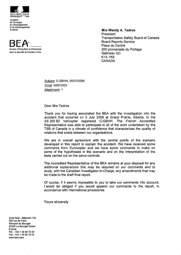
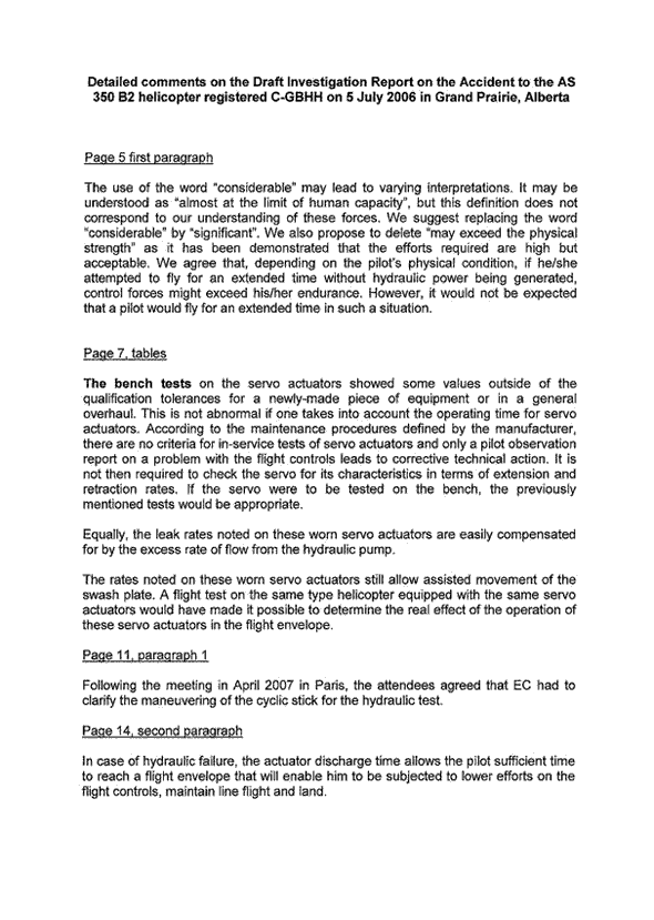
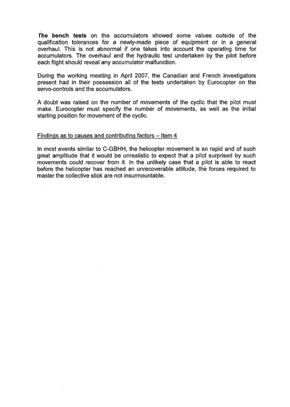
Unintentional Lift-off and Collision with Terrain
Highland Helicopters Limited
Eurocopter AS 350 B2 (Helicopter) C-GBHH
Grande Prairie Airport, Alberta
The Transportation Safety Board of Canada (TSB) investigated this occurrence for the purpose of advancing transportation safety. It is not the function of the Board to assign fault or determine civil or criminal liability. This report is not created for use in the context of legal, disciplinary or other proceedings. See Ownership and use of content. Masculine pronouns and position titles may be used to signify all genders to comply with the Canadian Transportation Accident Investigation and Safety Board Act (S.C. 1989, c. 3).
Summary
At 0830 mountain daylight time at the Grande Prairie Airport, Alberta, the Highland Helicopters Limited Eurocopter AS 350 B2 helicopter (C-GBHH, serial number 3180) was standing on the prepared hard surface outside the company hangar and running at flying rotor rpm (revolutions per minute). The pilot was in the process of conducting the pre-flight hydraulic servo accumulator test sequence when, during the lateral servo check, the helicopter tilted back sharply and became airborne.
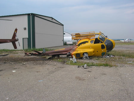
The pilot could not push the collective lever down and was unable to prevent the helicopter from lifting off to about 15 feet above the ground. The helicopter then turned left, descended tail down, and rolled to the right. The main rotor blades struck the ground and broke off, and the fuselage fell onto its right side. The pilot was not injured but the helicopter was substantially damaged; there was no fire. There was minor damage to an adjacent helicopter, but no persons were injured on the ground. The accident occurred during daylight and in calm, visual meteorological conditions.
Factual information
History of the Flight
Following an uneventful start-up, the pilot of C-GBHH began conducting his normal pre-flight hydraulic test sequence. In preparation for this pre-flight test, the pilot engaged the collective lock in the cockpit and established the rotor rpm (Nr) at 100 per cent, as required by approved procedure.
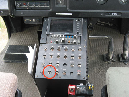
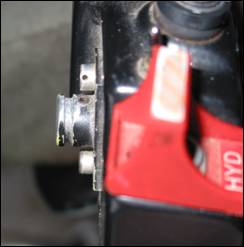
His practice was to select HYD TEST on the hydraulic accumulator test switch on the "VanIsle" centre console panel (see circle in Photo 2) and move the cyclic stick a number of times (normally 12 to 15 movements) in two specific directions—fore and aft, and laterally—so as to exhaust the servo accumulators. The pilot habitually performed these two functions in the same order each time: forward servo first, followed by the lateral servos.
The pilot observed that the forward servo accumulator exhausted after 14 fore-and-aft cyclic movements, which was consistent with his experience. He was about to continue with the lateral servo accumulator portion of the test sequence when he saw the attending aircraft maintenance engineer (AME) approaching the helicopter from the right-hand side, with the aircraft journey logbook in hand, indicating his wish to deliver the logbook to the pilot. In this model AS 350 B2 helicopter, the pilot is seated in the right-hand seat. The pilot then paused his test sequence and centralized the flight controls to provide the AME safe passage beneath the rotor disk. Once the AME was at the right-hand cockpit door, the pilot resumed the lateral portion of the accumulator test.
The pilot had moved the cyclic laterally only five times when the nose of the helicopter began to rise. The pilot was unable to prevent the helicopter from continuing to rise and the AME quickly moved away from his position at the right-hand side of the cockpit. Despite the pilot's efforts to lower the collective and stop the nose from rising, the helicopter became airborne in a pronounced nose-high attitude.
The helicopter quickly drifted backwards from the asphalt apron, turned about 90° to the left, and the tail guard on the lower vertical fin struck the ground and dug into the gravel surface now below. The helicopter slid back and rolled to the right, causing the landing skids and the main rotor blades to strike the ground. As a result of this heavy contact with the ground, the helicopter rolled over onto its right side. The rotor head and main rotor blades were destroyed; the blades shattered and were thrown over a large area. At the same time, the rear section of the tail boom broke off near the horizontal stabilizer forward attachment point and the tail rotor assembly tore out from the end of the tail boom.
After the roll-over, the engine continued to operate briefly, with the main transmission and rotor head turning, until the pilot pulled the throttle and the fuel cut-off levers to shut the engine down. During the sequence of events, the pilot did not operate the collective hydraulic cut-off switch or reset the hydraulic test switch. The pilot did attempt to push the collective lever down but was unable to move it.
Crashworthiness
This accident was survivable and the pilot escaped through the broken right-hand windshield. In general, the cockpit and cabin structures were not substantially damaged and the occupiable volume was not compromised. Only the windshield, the pilot door structure, the pilot seat, and the seat support rails were substantially damaged by the impact and roll-over forces.
Helicopter Information
| Manufacturer | Eurocopter |
| Type and Model | AS 350 B2 |
| Year of Manufacture | 1999 |
| Serial Number | 3180 |
| Certificate of Airworthiness | Issued 16 December 2003 (H-83) |
| Total Airframe Time | 3831 hours |
| Engine Type (number of) | Turbomeca Arriel 1D1 (1) |
| Rotor Type | STARFLEX – 3 blades, composite |
| Maximum Allowable Take-off Weight | 4961 pounds (2250 kg) |
| Recommended Fuel Type(s) | JP4, JP5, JP8, Jet A, Jet A1, Jet B |
| Fuel Type Used | Jet A1 |
The basis of certification for the AS 350 helicopter series is United States Federal Aviation Regulation (FAR) 27, Normal Category, effective 01 February 1965 including Amendments 27-1 through 27-10. Since France is the country of design, the French civil aviation authority, the Direction Générale de l'Aviation Civile (DGAC), issued the original product type certificate (H9EU) for the AS 350 B in October 1977.
In June 1978, the Canadian civil aviation regulator, Transport Canada (TC) issued Canadian type certificate number H-83 to the AS 350. In December 1990, TC certificated the AS 350 B2. The DGAC has recently become the European Aviation Safety Agency (EASA) with the same certification functions.
Helicopter Maintenance
Aircraft maintenance logbooks and records indicate that the aircraft was certificated, equipped, and maintained in accordance with existing Canadian regulations and approved procedures.
Engine Information
The engine installed in the accident helicopter was a Turbomeca Arriel 1D1 (serial number 9631) and was not damaged. Engine logs record that the engine was maintained and serviced in accordance with existing Canadian regulations and approved procedures. In consideration of the reported sequence of events, the investigation ruled out performance or mechanical malfunction of the engine in the accident circumstances.
Helicopter Weight and Balance
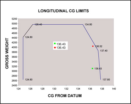
The maximum certificated gross weight for this model helicopter is 4961 pounds. Post-accident calculations reveal that at the time of the accident the helicopter weighed about 4040 pounds and that the longitudinal centre of gravity (CG) was about 136.5 inches from the datum. The weight and CG values were within the limits prescribed by the TC-approved rotorcraft flight manual (RFM).
The CG, however, was near the aft limit (see Figure 1). An aft CG position in flight requires the pilot to maintain more forward cyclic stick input than normal, thus reducing the available forward cyclic stick travel. In cases of limited cyclic travel in flight, the amount of forward cyclic movement available may be insufficient for the pilot to control the helicopter.
Pilot Information
Records show that the pilot was licensed and qualified for the flight in accordance with existing TC regulations and held a valid Canadian commercial helicopter pilot licence (CPL (H)). He had about 2100 hours of total flying experience on similar light helicopters, about 800 hours on the AS 350 helicopter, and had worked for the operator for just over three years.
In March 2006, the pilot received company flight training on the AS 350 B2 helicopter, including simulated hydraulic malfunctions that he performed correctly and well. Immediately after that training, the pilot successfully completed his most recent pilot proficiency check (helicopter) on the AS 350 B2.
Hydraulic Flight Control System
General Description
In flight, helicopter flight control loads, principally resulting from aerodynamic forces, are normally considerable. The flight controls in the Eurocopter AS 350 B2 helicopter are assisted by a single hydraulic system that reduces pilot workload during flight through servo actuators absorbing these flight control loads, thereby allowing the pilot to fly the helicopter with precision and reduced effort. Normal hydraulic system pressure is 40 bar (580 pounds per square inch (psi)). In the event of a loss of hydraulic pressure, however, the flight control loads revert to the unpowered condition. The helicopter can be controlled without hydraulic servo actuators but the pilot has to exert considerable muscular effort, which is difficult to gauge accurately, and, in some cases of extended flight, may exceed the physical strength or endurance of an individual pilot.Footnote 1 The AS 350 B2 is also equipped with a yaw load compensator that offloads much of the aerodynamic feedback force generated by the tail rotor.
The servo actuators on the AS 350 series helicopter are made by two approved manufacturers, Goodrich Actuation Systems (SAMM) and Dunlop. Except for a minor difference in the slide valve operation, the two actuator designs are identical in function and installation. According to Eurocopter, the helicopter may be fitted with either SAMM or Dunlop servos, or both.
Hydraulic Servo Actuator Operation
In total there are four hydraulic servo actuator units: three main rotor servos—one longitudinal and two laterals—provide nose-attitude and roll cyclic control, as well as collective pitch control; one tail rotor servo provides yaw control. Each of the four servos incorporates a hydraulic actuator, a pressure accumulator, and a solenoid valve (also called an electro-valve). Apart from airframe mounting differences, the four servo actuators on the control linkages are identical. The tail rotor servo incorporates the yaw load compensator.
The electro-valve is an electrically actuated device that relieves the high-pressure hydraulic fluid at each servo and the regulator unit, thus unpowering the servos simultaneously. The function of each accumulator is to provide its actuator with a small reserve of pressurized hydraulic fluid so that, in the event of loss of system hydraulic pressure, the pilot has a brief opportunity to reconfigure the helicopter to a flight regime of 40 to 60 knots, where the control feedback forces without hydraulic assistance are acceptable. The position adopted by the collective stick in this condition is about the same position it seeks during the hydraulic test procedures on the ground. The AS 350 series helicopter has no hydraulic system pressure gauge in the cockpit, nor is there a static pressure monitoring device for the accumulators.
Hydraulic System Control
The operation of the hydraulic system is controlled by the pilot using two switches in the cockpit: the hydraulic cut-off switch and the hydraulic accumulator test switch.
The hydraulic cut-off switch is a guarded toggle switch with two positions—ON or OFF—and is mounted on the pilot's collective stick. The switch is normally set to ON, allowing the servos to be powered when the hydraulic system is functioning correctly. When the pilot selects the switch to OFF, the hydraulic system is depressurized, the accumulators on the three main rotor servos are depressurized simultaneously, and the tail rotor load-compensating system retains its assist function (Eurocopter complementary flight manual (CFM) RR 7D, section 7.7). The tail rotor servo accumulator is not affected. The pilot then experiences higher-than-normal feedback forces on the flight controls.
In this particular helicopter, the hydraulic accumulator test switch is a two-position toggle switch mounted in the centre console switch panel (see Photo 2). Operating the switch on the ground verifies the correct function of the accumulators and it is normally set to the OFF position. Selecting the switch to HYD TEST depressurizes the hydraulic system (via the regulator unit) and simultaneously depressurizes the tail rotor yaw load compensator.
The RFM cautions pilots to avoid operating the hydraulic test switch in flight, because when the tail rotor yaw load compensator depressurizes, high tail rotor feedback forces are transmitted to the yaw pedals.
Hydraulic Servo Accumulators
By design, the hydraulic servo accumulators are charged with nitrogen to a pressure of 15 bar (218 psi ) that provides a finite reservoir of pressurized hydraulic fluid to the actuators. Since there is no device on the helicopter to monitor the existing pressure in an accumulator, Eurocopter requires the pilot to ascertain that all the accumulators are functional by conducting a specific pre-flight accumulator check. The prescribed test does not determine actual accumulator pressure, only that the accumulators are capable of providing hydraulic pressure for a limited number of flight control movements.
One of the principles of certification of the helicopter was the provision of a flight control system that, in the event of a hydraulic system failure, permitted the pilot to continue to manipulate the flight controls with reasonable feedback forces. The accumulator system was added to provide that opportunity, albeit finite and of short duration, for the pilot to establish a safety speed. The accumulators are an intrinsic part of the hydraulic system and crucial to its function; their proper function is required for flight, hence the pre-flight test.
Hydraulic System Examination
Main Rotor Hydraulic Servo Actuators
The hydraulic servo actuators installed on the accident helicopter were SAMM and Dunlop, which have a service life of 3000 or 1800 hours respectively before requiring overhaul (referred to as time between overhaulor TBO); the recorded time left on the main rotor servos before next overhaul varied from about 85 to 2326 hours. The following table summarizes the servo data:
| Servo Location | Make | Part number | Serial number | TBO | TSOFootnote 2 | Time Left |
|---|---|---|---|---|---|---|
| Left lateral | SAMM | SC 5083 | 638 | 3000 | 764 | 2236 |
| Right lateral | Dunlop | AC 67244 | DW 215 | 1800 | 1715 | 85 |
| Forward | SAMM | SC 5084 | 459 | 3000 | 674 | 2326 |
| Tail Rotor | Dunlop | AC 67032 | DV 386 | 1800 | 1689 | 111 |
Servo Examination and Functional Tests
On 15 August 2006, the hydraulic servos were examined and functionally tested in Langley, British Columbia, undisturbed as fitted to the accident helicopter, under the direct supervision of the TSB. Each servo actuator passed all preliminary functional tests and no servo anomaly was detected.
Before the functional tests began, the accumulators for the three main rotor servo actuators were examined and all were found to have lower pressure than the specification value of 15 bar (218 psi) as shown in the adjacent table. The accident investigation team operated the hydraulic system components and found variance in the number of cyclic movements required to exhaust the forward and lateral servo accumulators after the hydraulic system pressure was shut off. It took 9 to 10 fore-and-aft cyclic movements and 4 to 5 lateral cyclic movements to exhaust the respective accumulators; these results were repeated consistently.
| Servo Location | Accumulator Pressure – bar (psi) |
|---|---|
| Left lateral | 10.0 (145) |
| Right lateral | 4.1 (60) |
| Forward | 4.5 (65) |
In September 2006, the four hydraulic servo actuators with their accumulators and the regulator unit were removed from C-GBHH and taken by the TSB to the Eurocopter Canada facility in Fort Erie, Ontario, for further examination and testing. Each servo was bench-tested completely against the certification specifications for a new servo under the direct supervision of the TSB. Each servo actuator passed all functional tests except for the extension and retraction speeds. The minimum and maximum travel speeds for the Dunlop servo actuators are 100 and 120 mm/s respectively. For the SAMM actuators, the minimum and maximum travel speeds are 100 and 160 mm/s. The maximum permissible speed differential between extension and retraction in an individual servo is 15 per cent of the faster speed. The following table summarizes the results of the servo speed tests carried out in Fort Erie:
| Servo Location | Make | Limits | Extension | Retraction | Differential | Pass/Fail |
|---|---|---|---|---|---|---|
| Left lateral | SAMM | 100/160 | 114 | 135 | 21 (16%) | Fail |
| Right lateral | Dunlop | 100/120 | 109 | 91 | 18 (17%) | Fail |
| Forward | SAMM | 100/160 | 120 | 123 | 3 (2%) | Pass |
| Tail rotor | Dunlop | 100/120 | 90 | 121 | 31 (26%) | Fail |
These servo actuator rates were measured under bench-test conditions, gathered from servos that had been in service for varying periods. The effect of in-flight conditions upon the specification performance of the servos is not known because in-service specification monitoring is not done, nor is it required by regulation. Servo functionality is based solely on condition; normally when a servo malfunctions, it is removed for overhaul.
It is important to note that a servo and its accumulator are not considered an inseparable unit, that is, the servo actuator has a TBO but the accumulator is an on-condition item and is not subject to periodic overhaul or inspection. It is conceivable that an accumulator, with undetected marginal performance, could remain on the airframe for an indefinite period.
During the examination of the servo actuators in Fort Erie, the nitrogen pressure charge in each of the three main rotor servo accumulators was again measured, with the results confirming the original lower-than-specification pressures. The tail rotor servo accumulator pressure was not measured, but the compensator unit was inspected and tested in accordance with overhaul procedures and no anomaly was found.
The wide static variance of accumulator pressure is of some interest because it indicates that the accumulators would have exhausted at different times following a loss of system hydraulic pressure, thereby potentially leading to asymmetrical flight control forces. By design, this undesirable situation is prevented by the pilot operating the hydraulic pressure cut-off switch on the collective stick, thereby dropping system pressure on each servo and accumulator at the same time, provided that the pilot operates the switch before any of the accumulators is exhausted.
In concert with recent investigations into other occurrences involving loss of control and hydraulic malfunction, the pressures in the accumulators from other AS 350 helicopters, both accident-related and in-service, were measured using consistent methods and tools. The results of some of those examinations are tabled below (values are indicated in psi):
| Servo Location | Sample 1 | Sample 2 | Sample 3 | Sample 4 | Sample 5 | Sample 6 |
|---|---|---|---|---|---|---|
| Left lateral | 35 | 90 | 145 | 100 | 150 | 160 |
| Right lateral | 87 | 153 | 60 | 10Footnote 3 | 175 | 45 |
| Forward | 90 | 90 | 65 | 55 | 160 | 105 |
Hydraulic Servo and Accumulator pre-Flight Tests
Servo and Accumulator Test Procedures
The purpose of this pre-flight test is to assess the function of the main rotor servo actuator accumulators individually and to assure the pilot that they are capable of providing at least two flight control movements before hydraulic pressure is exhausted. This action is intended to allow the pilot to establish the helicopter in a stabilized flight regime that has been shown to have acceptable flight control loads, thus enabling the pilot to maintain control.
The accumulators are tested during each pre-flight check by the pilot operating the hydraulic test switch and moving the cyclic stick to verify that the accumulators are providing hydraulic assistance. Furthermore, the test verifies the integrity of each accumulator by checking its recovery time.
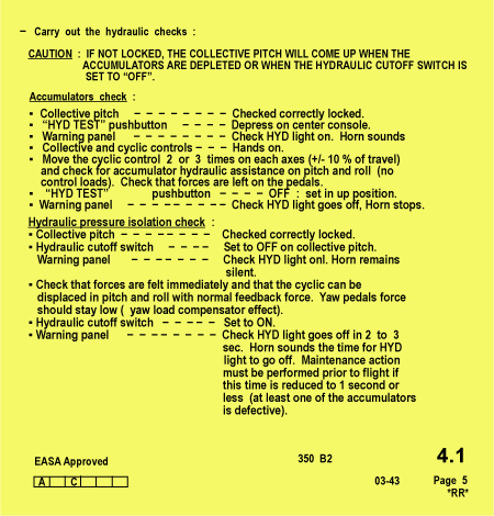
The pre-flight hydraulic test procedures prescribed in the Eurocopter AS 350 B2 RFM RR 3a, page 5 (see adjacent text box) state that there should be two or three cyclic control movements before pressurized hydraulic fluid from the accumulator is depleted. The accumulator test is carried out on the ground at normal flying (flight) rotor speed, that is, at least 375 rotor rpm, and with the collective stick lock engaged. In summary, the test requires the pilot to select the hydraulic test switch to the HYD TEST position and move the cyclic stick two or three times to verify hydraulic assistance in the pitch and roll axes. The pilot then selects the switch to the normal OFF position. At the end of this hydraulic isolation check, the pilot verifies that the accumulators recharge within two to three seconds, but no faster than one second. An interval of one second or less indicates that at least one of the accumulators is defective.
Uncommanded Collective Control Stick Movement
It is important to note that the pre-flight hydraulic accumulator test procedures prescribed in the TC-approved RFM caution that the collective stick will rise up when the accumulators exhaust or when the cut-off switch is set to OFF. This uncommanded collective movement is a design characteristic of the rotor control system in the AS 350 helicopter, but is prevented on the ground by engaging the collective lock correctly. This situation, however, requires two conditions before it can occur: the collective lock be disengaged, and at least one of the main rotor hydraulic servo accumulators be exhausted. This characteristic is known to the helicopter manufacturer, Eurocopter, TC, and many Canadian operators of the AS 350 series helicopter. It is the subject of Airworthiness Directive (AD) CF-2003-15 and subsequent revisions, as well as DGAC AD F2004-174 (CF-2003-15 was rescinded when F2004-174 was promulgated).
Canadian Airworthiness Directives and Airworthiness Notices
Transport Canada issued an urgent AD, CF-2003-15, dated 16 May 2003, which in part required pilots of the AS 350 helicopter to functionally check the hydraulic system and accumulators before flight. This original AD was superseded by revised AD CF-2003-15R1, dated 01 July 2003, which prescribed that the pre-flight accumulator check be carried out before every flight.
In September 2003, TC issued Airworthiness Notice (AN) D006, Edition 1, to address its concerns with the flight control characteristics of the AS 350 when hydraulic system pressure was lost. Eurocopter tests showed that an uncommanded servo actuator movement is possible when one lateral accumulator is depleted and the other is charged. The AN also notes that this uncommanded movement is prevented in flight when the pilot, following a hydraulic failure, slows the helicopter promptly to a specified "safety speed" and sets the hydraulic cut-off switch on the collective lever to OFF. When the pilot turns the switch off, any unbalanced force caused by asymmetric residual accumulator pressure is avoided. If the cut-off switch is not used, and if the accumulators deplete at a different rate by normal flight control movements, sustained and asymmetric hydraulic pressures may occur. In this Grande Prairie accident, the pilot had not yet operated the cut-off switch.
Testing Accumulators to Exhaustion
The accumulator portion of the test prescribed by the superseded Canadian AD purposely required the depletion of all the accumulators to provide a timely warning to the pilot that an accumulator was gradually failing (leaking internally). This deterioration would have been identified by the pilot noting a progressive reduction in the number of cyclic movements to reach accumulator exhaustion each time the pre-flight test was done. After such a test, the pilot knew that a certain number of cyclic movements caused the accumulators to exhaust, with the added benefit of giving the pilot a tactile demonstration of the associated cyclic response and forces. The negative side of this procedure is that the pilot is deliberately exposed to uncommanded collective movement should the collective lock disengage. However, that movement is expected and would be the same as if the accumulator were failing and became exhausted after the two cyclic movements. In either case, an unrestrained collective stick would rise sharply to the same position.
The hydraulic test technique currently prescribed in the RFM (see page 10) requires the pilot to only make two or three cyclic movements and not to accumulator depletion. This procedural difference intends to reduce the exposure to uncommanded collective movements resulting from accumulator depletion. In this RFM procedure, the pilot is verifying that the accumulators are still charged after the two or three movements; however, there is no indication as to how many more movements any one accumulator would still provide.
It is clear that the test would not identify an accumulator that would exhaust after, for example, four cyclic movements. Furthermore, assuming the collective lock is defective or disengaged, the protection the pilot had from any uncommanded collective movements is also lost with the "two-or-three-movement" technique once the failing accumulator reaches the point where two or three movements exhaust it. The negative side to this procedure remains that the pilot is exposed to uncommanded collective movement should the collective lock disengage, except that in this case the pilot could be caught unexpectedly. In the previous "exhaustion" procedure, the pilot was expecting it to happen because that was the purpose of the test.
Although the prescribed pre-flight test assumes that the number of cyclic movements remaining before an accumulator is exhausted is two to three, the reality of control movements in flight is that a combination of collective and cyclic movements is necessary to return the helicopter to the safety speed, and in some cases, it is unlikely that only two or three flight control movements are sufficient to achieve that reduced speed.
In this accident, the pilot's practice was to use the accumulator test prescribed by the superseded Canadian AD rather than the procedure in the RFM.
Pre-flight Test Rotor rpm
The accumulator test is prescribed to be conducted on the ground at normal flying rotor speed (at least 375 rpm). This condition ensures that the hydraulic system operating pressure and volume are consistent with normal flight. Examination of the hydraulic system and the operating characteristics of the pump and servos show that full operating hydraulic system pressure is achieved at lower rotor rpm, in the order of 50 per cent rotor rpm. Discussions with several Canadian operators of this helicopter model reveal that the hydraulic system can be, and has been, tested successfully at lower rotor rpm without adverse effect.
Lower rotor speed produces lower aerodynamic forces that are insufficient for flight. Conducting the hydraulic test at lower rotor speed introduces a safety benefit by reducing the risk of unintentional and violent helicopter movement resulting from uncommanded servo response to accumulator exhaustion, should the collective lock become disengaged.
Collective Stick Locking Device
The investigation revealed a concern within the Canadian helicopter industry with the collective locking device on the AS 350 helicopter. Anecdotal information and documented cases show that the locking device is prone to premature or uncommanded release.
On 09 October 2003, Eurocopter France issued Alert Service Bulletin (ASB) number 67.00.27, which, in summary, requires the inspection of the collective lock device ("button") for wear on all AS 350 model helicopters. This ASB was precipitated by an accident where a helicopter became airborne during the hydraulic test procedure and it was found that the collective locking plate had disengaged because of excessive in-service wear on the lock button.
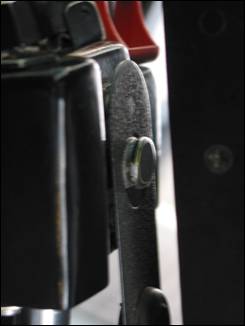
Preliminary examination of the locking plate in C-GBHH does show wear, but it also reveals clear signs of frequent improper engagement of the device (see Photo 3). By design, the locking plate engages the collective lock button in a machined groove intended to secure the spring steel locking plate. The plate is released by pushing down on the collective lever, allowing the plate to release from the groove and spring forward away from the lock button. In practical tests, this simple function occurred without fault when the plate was correctly engaged in the groove.
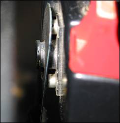
If the locking plate is engaged past the collective button, the plate catches on the machined shoulder on the button and locks the collective in that manner (see Photos 4 and 5). This position is outside the machined groove and it takes less force to release the locking plate than if it had been correctly engaged in the groove. Again, practical tests showed that the plate was positioned past the groove on most occasions, thus locking the collective improperly. The location of the device prevents this error being easily detected by the pilot and the only practical verification that the lock has engaged is the tactile sense that the collective cannot rise.
The consequence is that the collective lock may be inadvertently released by the pilot bumping the collective, a force that normally would not cause it to release were the locking plate in the groove. The intent of the ASB is to prevent uncommanded release of the collective lock owing to wear on the anterior lip of the lock button; however, the safety action of the ASB does not address the circumstance of improper engagement of the lock.
The ASB is a one-time only instruction. It is clear that this part will continue to wear through normal service operation and now-serviceable locks will deteriorate without benefit of further examination. Eurocopter has since changed the instructions contained in the master servicing recommendations (MSR) chapter 05-20-01, as well as the associated work cards, to incorporate a periodic check of the button every 500 hours of service.
Analysis
General
The pilot of this helicopter experienced a sudden upward movement of the collective stick during the prescribed pre-flight hydraulic accumulator check procedure. However, the pilot was unable to prevent the helicopter from becoming airborne and could not regain control before the helicopter struck the terrain. The uncommanded collective stick movement is a characteristic of the rotor system design and pre-flight procedures are in place to prevent it.
The factual information in this report explains the mechanical reasons for the uncommanded collective stick movement during this hydraulic test. Without the collective lock in place, it is clear that the helicopter flight controls behaved in a predictable manner and no further analysis is needed to explain this behaviour itself.
This analysis will therefore focus on the reasons behind the chain of events that allowed the collective to move and cause the accident. Also, several physical and procedural anomalies were discovered that had an impact on the safety defences that are built into the flight control system and its operation, including those that have already resulted in TSB safety action.
Circumstances Leading to Uncommanded Collective Movement
The original design of the locking button on the pilot's collective stick permitted incorrect engagement of the locking plate. This anomaly created a situation where the downward force on the collective stick necessary to release the lock was considerably less than it would have been had the lock been engaged correctly. Once the lock was released, the collective stick was free to move up.
In this accident, the pilot exhausted the forward servo accumulator as part of his usual pre-flight checks, but stopped his test and centralized the flight controls to allow the AME under the rotor disk. This action likely included light downward pressure on the collective stick as a matter of normal reflexive action by the pilot. Such pressure was sufficient to release the improperly engaged lock and free the collective; at this stage, the pilot was unaware that the lock had disengaged.
Once the pilot continued testing, it was only a matter of time before the collective stick rose up as a result of the lateral accumulator(s) exhausting and causing the flight controls to move to the non-hydraulic-powered position.
Weight and Balance
The helicopter was well below maximum certificated gross weight and the longitudinal CG was near the aft limit. As a result of the relative light weight of the helicopter, a lesser amount of collective pitch application would have been necessary for the helicopter to become airborne. The aft CG condition would have required the pilot to maintain more forward cyclic input in flight than normal and thus reduced the available forward cyclic stick travel. Although not a significant factor until the helicopter became airborne, this reduction in forward cyclic stick travel made the helicopter vulnerable to nose-high attitudes; the onset speed and magnitude of this nose-up force may have lessened the pilot's ability to prevent the nose of the helicopter from rapidly rising.
Hydraulic Test Procedures
It could be said that the former hydraulic test procedures prescribed by the original Canadian AD incorporated a proactive approach toward detecting a failing accumulator whereas the procedure presently contained in the RFM is reactive. That is, the procedure only identifies a failed accumulator after it cannot supply the required two or three cyclic control movements; up to that point, the failing accumulator is undetectable.
There is some doubt regarding the number of cyclic movements prescribed by Eurocopter for the procedures for both the hydraulic system ground test and the in-flight loss of hydraulic pressure. This doubt was primarily created by inconsistent interpretation of the procedures promulgated in the RFM, and timely revision of the procedures by Eurocopter is necessary.
Furthermore, the diagnosis of the final stage of the test (both the former and current) relies on a small interval of one second or less to identify a defective accumulator. Given that pilots would have varying interpretations of this time, this subjective factor makes the recharging element of the pre-flight test an insensitive method of assessing the integrity of the accumulator.
Another factor in the circumstances leading to the accident was the procedural requirement to establish full flying rotor rpm (revolutions per minute) for the pre-flight hydraulic test procedure. Coupled with low gross weight and exhausted accumulators, the flying rotor rpm placed the helicopter in a condition to certainly become airborne were the collective stick lock to release.
Servo Actuator Anomalies
The servo actuators were tested and found anomalous in two particular areas: inconsistent piston extension and retraction travel rates, and low accumulator pressures.
Though it could not be proven that the inconsistent servo travel rates directly contributed to the accident, there is doubt that such servo behaviour is always benign. It is possible that a combination of servo performance tolerance limits, though individually insignificant, could act synergistically in a manner that causes the servo to malfunction. Because the servos always leave the overhaul/manufacturing facility well within the required specification tolerances, it is clear that, in some cases, a servo can deteriorate in service. At this time, however, no meaningful link to the servo malfunctions has been made.
Regardless, Eurocopter tests have shown that asymmetric lateral servo accumulator depletion can cause uncommanded servo movement. Information also exists to demonstrate that the helicopter is difficult to control in the event of unequal exhaustion of the accumulators. Following pertinent ANs and ADs, modifications to the hydraulic system were mandated by both Canada and France. These modifications allowed pilots to shut off the hydraulic system pressure and exhaust the accumulators simultaneously, thus providing a controlled transition into non-hydraulic-assisted flight.
Hydraulic Accumulator Pressure Monitoring
Part of the certification basis for the helicopter required that the pilot be able to continue to manipulate the flight controls with reasonable feedback forces in the event of a hydraulic system failure. The hydraulic accumulators are the sole approved mechanical devices providing that guarantee and they are crucial to the proper function of the flight control system in flight. With an unserviceable accumulator, the helicopter is not permitted to dispatch.
The pre-flight test is the last opportunity for the pilot to ascertain that the accumulators are functional. Apparently, the test methodology is not particularly effective since many instances of undetected low accumulator pressures have been found, with a range of pressures from 35 to 175 psi, where 218 psi would have been expected. Adding to the uncertainty of the test is the situation where these low-pressure accumulators were in service without any indication given to either pilots or maintenance personnel as to their low-pressure state, and where they all apparently passed the pre-flight test procedures. The underlying issue remains that the revised hydraulic accumulator test per se is not effective in identifying accumulators that do not contain the prescribed pressure. There is still the risk that flight in the AS 350 helicopter could commence with one or more marginally serviceable hydraulic accumulators, thereby reducing the level of defence against hydraulic system failure.
Given that this critical element of the flight control system is subject to progressive and latent failure, a simple method of measuring the actual accumulator pressures before flight would appear to be an indispensable component. While this device would not alert the pilot to in-flight failure of an accumulator, it would prevent take-off with a marginal pressure resulting from progressive deterioration of the accumulator unit.
Findings
Findings as to causes and contributing factors
- The design of the lock button on the collective stick allowed improper engagement with the locking plate and led to premature release of the collective stick during the hydraulic test procedure.
- When the pilot interrupted his pre-flight hydraulic test sequence, the collective stick lock released without his knowledge.
- When the lateral accumulator(s) exhausted, the unlocked collective stick rose up sharply and caused the helicopter to become airborne; such collective movement is a predictable characteristic of the AS 350 B2 helicopter.
- The rapid feedback forces on the flight controls, resulting from the exhausted accumulators, were such that the pilot was unable to lower the collective stick and prevent the helicopter from becoming airborne, nor could control of the helicopter be regained before it struck the ground.
- The helicopter centre of gravity was within the limits of the approved rotorcraft flight manual (RFM); however, it was near the aft limit and this situation exacerbated the nose-up attitude.
- The rotor speed for the pre-flight hydraulic test was required by approved procedure to be at normal flying rpm (revolutions per minute); however, during the pilot's test process when one of the accumulators exhausted with the collective stick lock disengaged, such rpm enabled the helicopter to become airborne inadvertently.
Findings as to risk
- The accumulators for the three main rotor servos had lower pressure than specification value, yet no indication of that condition had been given to either the pilot or maintenance personnel.
- The approved maintenance documents for the AS 350 B2 helicopter required that the accumulators be charged with nitrogen to 15 bar (218 pounds per square inch); however, there was no visual method of monitoring the pressure in each hydraulic accumulator and a significant pressure differential could develop before it became apparent to the pilot.
- In the event of a hydraulic system pressure loss in the AS 350 B2 helicopter, the condition of significant pressure differential in the main rotor accumulators leads to unequal depletion of the reserve of pressurized hydraulic fluid, thereby causing asymmetric servo actuator movement, high and unpredictable flight control forces, and a potential loss of control in flight.
- The current hydraulic accumulator test is not effective in identifying accumulators that do not contain the prescribed pressure. The risk is that flight in the AS 350 helicopter could commence with one or more marginally serviceable hydraulic accumulators, thereby reducing the level of defence against subsequent hydraulic system failure.
- The prescribed pre-flight hydraulic test procedures required the pilot to move the cyclic at least twice to verify that the servo continued to be powered. An earlier airworthiness directive from Transport Canada required the cyclic to be moved to exhaustion and gave a more meaningful assessment of accumulator condition.
- The prescribed hydraulic system ground-test and in-flight procedures contained in the RFM are not consistent with Eurocopter's procedures and need to be clarified.
- The hydraulic servo actuator has a time between overhaul (TBO) of either 1800 or 3000 hours in service and is therefore subject to periodic overhaul and specification adjustment, whereas the accumulator unit is an on-condition item and is not subject to overhaul. As a result, an accumulator with undetected marginal performance could remain on an airframe for an indefinite period.
Other findings
- There is no meaningful data concerning the effect of in-flight conditions upon the specification performance of the hydraulic servo actuators because in-service monitoring is not done, nor is it required by regulation.
- The upward collective movement caused by the exhaustion of the hydraulic accumulators is a design characteristic of the rotor control system in the AS 350 B2 helicopter and is effectively prevented on the ground by correctly engaging the collective lock.
- Functional tests with the servo actuators revealed inconsistent travel rates that were beyond the manufacturers' specifications; however, no data exist to conclude that this anomaly was applicable to this or other loss-of-control accidents in the AS 350 B2 helicopter.
Safety Action Taken
Transportation Safety Board of Canada (TSB)
Collective Stick Lock Device
On 06 June 2007, the TSB issued Safety Advisory A06P0123-D1-A1 (Improper Engagement of Collective Lever Lock in AS 350 Helicopters) suggesting that Transport Canada (TC) may wish to pursue the issue of improper engagement of the collective lever lock with the helicopter manufacturer, with the aim of improving the functionality and durability of the collective lever lock, thus reducing the risk of unintentional release.
Hydraulic Accumulators Test Procedures
On 18 June 2007, the TSB issued Safety Advisory A06P0087-D3-A1 (AS 350 Helicopter pre-Flight Hydraulic Test – Duration of Cyclic Movements) to TC, which urged a review of the rotorcraft flight manual (RFM) approved pre-flight test procedures for the hydraulic accumulators. In summary, the advisory noted that the present procedures of moving the cyclic two or three times was insufficient to ascertain in a timely manner that an accumulator was failing, that is, losing pressure progressively. The TSB also noted that the former procedures prescribed in expired Canadian Airworthiness Directive CF-2003-15R2 took a proactive approach and were satisfactory in alerting pilots and maintenance personnel of a failing accumulator.
In July 2007, TC sent a letter to the European Aviation Safety Agency (EASA) requesting that EASA review the issues referenced in the advisories to determine if corrective action could be implemented.
Rotor rpm for Hydraulic Test Procedure
On 06 June 2007, the TSB issued Safety Advisory A06P0123-D2-A1 (AS 350 Helicopter Hydraulic Accumulator Test – Rotor rpm Requirement ) suggesting that TC may wish to examine and review the requirement to conduct the hydraulic test procedure at 100 per cent rotor rpm.
Eurocopter France
Rotor rpm for Hydraulic Test Procedure
In September 2006, the helicopter manufacturer, Eurocopter France, issued a revision to the operating procedures of the approved RFM for the AS 350 B3 helicopter. It modified the rotor rpm required for the hydraulic accumulator test to be set to flight idle, which eliminated the possibility of the helicopter becoming airborne were the collective lock to disengage. At the time of this report, however, there has been no such change for the AS 350 BA/B2 helicopters.
Hydraulic Test Procedures
TSB research into the RFM procedures revealed an inconsistency in the interpretation of the number of cyclic movements required by Eurocopter for this procedure. As well, the prescribed hydraulic system ground-test and in-flight procedures contained in the RFM are not consistent with Eurocopter's procedures. As a result, Eurocopter plans to revise the RFM accordingly.
Collective Stick Locking Button
Eurocopter has designed a modified collective locking button to replace the original design as described in this report (new part number 350A27-3155-22). The shape of this new component evidently prevents improper engagement or premature release of the collective stick. Eurocopter has scheduled this improved part to be available to operators of the AS 350 helicopter in October 2007.
This report concludes the Transportation Safety Board's investigation into this occurrence. Consequently, the Board authorized the release of this report on .
