Hydraulic Pump Failure
Bombardier BD-100-1A10, C-GFHR
Geneva, Switzerland
The Transportation Safety Board of Canada (TSB) investigated this occurrence for the purpose of advancing transportation safety. It is not the function of the Board to assign fault or determine civil or criminal liability. This report is not created for use in the context of legal, disciplinary or other proceedings. See Ownership and use of content. Masculine pronouns and position titles may be used to signify all genders to comply with the Canadian Transportation Accident Investigation and Safety Board Act (S.C. 1989, c. 3).
Summary
A Bombardier BD-100-1A10 aircraft (registration C-GFHR, serial number 20016) operated by Fairmont Hotels and Resorts was en route between Prague, Czech Republic and Geneva, Switzerland. At 1038 central European summer time, the flight crew had completed their "in-range" checklist, which included switching the direct current (DC) hydraulic pumps from "OFF" to "AUTO". Approximately two minutes after the switch was selected to "AUTO", an "L HYD DC PUMP FAIL" caution message was displayed. There were no other abnormalities and the crew continued with an otherwise uneventful landing at Geneva. After deplaning, the flight crew noted soot on the side of the fuselage trailing aft from the battery bay door. The flight crew proceeded to open the battery bay door and found there was an acrid electrical fire odour. The flight crew then opened the rear bay and found soot and a burned wire on the positive terminal of the left DC motor pump filter assembly.
Factual information
The weather at the time of the incident was reported as follows: visibility greater than 6 statute miles, wind 240° magnetic at 8 knots, temperature 14°C, dew point 11°C, and atmospheric pressure 29.92 inches of mercury.
Records indicate that the crew was certified and qualified for the flight in accordance with existing regulations.
The aircraft was equipped with left (LH) and right (RH) DC motor pumps (DCMPs) that are located in the aft equipment bay. The two electric hydraulic pumps are to provide additional hydraulic capability to the system during take-off and landing. They also provide limited system contingency operation for specific failure modes.
Control of the DCMPs can be either automatic or manual. The two control switches are mounted on the hydraulic control panel in the cockpit pedestal. The DCMPs use three-position, double-pole switches. With the DCMP switches in the "AUTO" position, a DCMP will automatically turn on when its associated engine-driven pump fails, or when the flaps are not at zero and at least one aircraft generator is operational. In manual mode, the DCMP is turned on or off by the flight crew. The pumps are each protected by a 0.5-amp remote circuit breaker that provides a control power supply to the main power circuit breaker (PCB) for each DCMP. Turning the DCMP switch to the "OFF" position will remove all electrical power to the DCMP. The aft equipment bay is not equipped with either smoke or fire detection equipment and there is no fire suppression system, nor are these required by regulation.
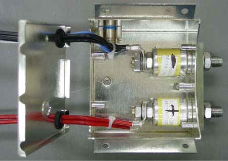
Mounted to the top of each DCMP is an electromagnetic interference (EMI) filter assembly. The filter assembly consists of a stainless steel box with two wound capacitors inside. One end of each capacitor is soldered to the filter box near the terminal studs and the other end is connected to the terminal stud. The terminal studs are bolts that pass through the centre of the capacitors and the nut at the inside end of the capacitor. One end of the terminal studs provides an attachment for the positive or negative electrical supply for the DCMP. The other end has electrical leads attached and routed out of the box for electrical connection to the DCMP (see Photo 1). The inside of the filter assembly is filled with a specific weight of potting compound which acts as a heat sink and vibration damper for the capacitors. The potting compound almost completely covers the capacitors. A stainless steel plate is soldered to the bottom of the box of the assembly, completely sealing the assembly.
The filter assembly is attached to the DCMP via four machine screws. Attachment of the electrical supply leads for the aircraft is accomplished via the brass stud of the capacitor and a nut and washer. Torques of the attachment nuts are critical to ensuring proper electrical conductivity.
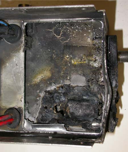
An examination of the left DCMP showed that the EMI filter had overheated at the capacitor attached to the positive lead and completely melted the positive terminal attachment stud. Removal of the filter revealed a burn-thru on the bottom of the filter assembly and build-up of molten metal on the top of the DCMP. The DCMP had accumulated 684.5 flight hours and 272 flight cycles.
The DCMP filter assembly overheat on the occurrence aircraft is the first known in-flight failure of this type. However, at least two other similar filter assembly failures have occurred in the past year. Both of these occurred while the aircraft were on the ground. In November 2006, the DCMP on aircraft S/N 20022 failed during ground runs. In April 2007, the DCMP on aircraft S/N 20023 failed while the aircraft was taxiing. Date codes on these two filters indicate they were from the same batch. The date stamp on the occurrence filter assembly was destroyed by the heat damage.
The top and bottom of the filter assembly were machined off and the inside of the filter assembly was examined (see Photo 2). A portion of the negative terminal of the capacitor was above the potting material. The positive terminal of the capacitor was destroyed with very little remaining. The damage was consistent with an electrical short within the capacitor.
Bombardier and Parker Hannifin Corporation, the DCMP manufacturer, have conducted numerous tests to determine the cause of the failure, but have been unable to identify the root cause.
Analysis
When the flight crew selected the hydraulic pumps from the "OFF" position to the "AUTO" position in accordance with their checklist, the DCMP would have energized. This possibly caused the capacitor filter to overheat and a caution message was displayed in the cockpit that the pump had failed. There were no smoke or fire warnings because there is no requirement to have smoke or fire detection equipment in the aft equipment bay.
It could not be determined when the melting or burning started or stopped, and there was no identifiable discrepancy that would have caused the capacitor attached to the positive terminal of the EMI filter to overheat and fail.
Finding as to Causes and Contributing Factors
- The capacitor attached to the positive terminal of the electromagnetic interference (EMI) filter mounted to the left DC motor pump (DCMP) failed for unknown reasons, causing the positive terminal to melt and burn the associated wiring.
Safety action
As a precaution, the following Bombardier advisory wire (AW), Aircraft Flight Manual (AFM) temporary revisions (TRs) and service bulletins (S/Bs) were issued by Bombardier and Parker Hannifin Corporation (Parker) to address the problem. The new DC motor pump (DCMP) configuration identified by the service bulletins and certified by Bombardier and Parker eliminates the capacitor from the electromagnetic interference filter assembly:
- 13 July 2007 - Bombardier issued AW300-29-0069 Rev. 2, advising operators of the problem.
- 01 August 2007 - Bombardier issued AFM TR-44 temporarily restricting the operations of the DCMP during flight.
- 06 August 2007 - Bombardier issued S/B 100-29-12 to check DCMPs for overheating.
- 20 August 2007 - Bombardier issued S/B 100-29-12 Rev. 01 to check DCMPs for overheating.
- 21 September 2007 - Parker issued S/B 955805-5-29-380 to replace the DCMP filter and re-identify the DCMP as P/N 955805-7 (from a -5).
- 11 October 2007 - Bombardier issued AFM TR-44-1 temporarily restricting the operations of the DCMP during flight.
- 04 December 2007 - Parker issued S/B 955805-5-29-380 Rev. 01 to replace the DCMP filter and re-identify the DCMP as P/N 955805-7 (from a -5).
- 05 December 2007 - Bombardier issued S/B 100-29-11 to replace the DCMP filter and re-identify the DCMP as P/N 955805-7 (from a -5).
- 21 December 2007 - Bombardier issued S/B 100-29-11 Rev. 01 to replace the DCMP filter and re-identify the DCMP as P/N 955805-7 (from a -5).
This report concludes the Transportation Safety Board's investigation into this occurrence. Consequently, the Board authorized the release of this report on .

