Limited Power - Hard landing
Prism Helicopters Limited
Eurocopter AS 350-B3 (Helicopter) N530NA
Pitt Meadows, British Columbia, 2 nm W
The Transportation Safety Board of Canada (TSB) investigated this occurrence for the purpose of advancing transportation safety. It is not the function of the Board to assign fault or determine civil or criminal liability. This report is not created for use in the context of legal, disciplinary or other proceedings. See Ownership and use of content. Masculine pronouns and position titles may be used to signify all genders to comply with the Canadian Transportation Accident Investigation and Safety Board Act (S.C. 1989, c. 3).
Summary
The Eurocopter AS 350-B3 (serial number 3209, registration N530NA) was being utilized for training on Douglas Island, two nautical miles west of Pitt Meadows Airport, British Columbia. There were two crew members onboard: the pilot-in-command (training pilot) was the pilot flying and was seated in the left (co-pilot) seat; the trainee pilot was seated in the right seat. At about 1100 Pacific standard time, the helicopter was hovering with its 100-foot longline positioned near the top of a 30-foot tree. After descending about 10 feet, the pilot attempted to arrest the descent by raising the collective; however, the helicopter continued to descend. The pilot lowered the collective, manoeuvred the helicopter to a clearing, and then pulled the collective all the way up to slow the rate of descent, but the helicopter impacted the ground heavily. The right side pilot seat base was fractured and collapsed. The trainee pilot received a minor injury. The training pilot was uninjured. The aircraft skid gear, belly panels, and main rotor blades were damaged. There was no fire. The emergency locator transmitter did not activate.
Factual information
History of the Flight
With the engine in a limited power condition, the pilot-in-command attempted to arrest the descent by raising the collective, but the helicopter continued to descend slowly. He immediately lowered the collective and twisted the throttle toward the "Vol" (flight) setting; however, it was already at that setting. He then pitched the nose forward and executed a 180° turn in preparation for an emergency landing. Upon impact, the aircraft settled about 15° to the right and the main rotor blades contacted some small trees. The engine was still running at low RPM, as was the rotor. The pilot shut off the engine and applied the rotor brake.
Weather
At the time of the accident, the weather conditions were cloudy with light rain showers, visibility was about five statute miles, wind was light and variable, and the temperature was about 3°C.
Operations
The helicopter had a United States (U.S.) registration and was being operated in Canada by Prism Helicopters Ltd. in accordance with the Canadian Aviation Regulations (CARs).
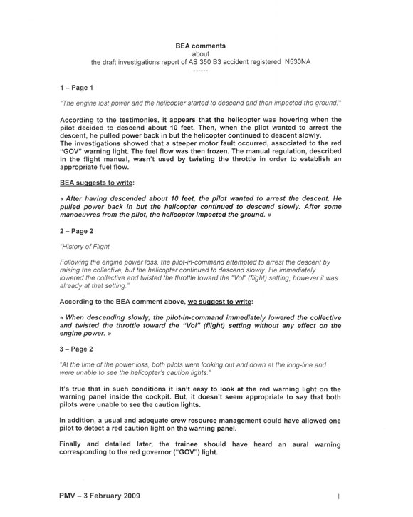
The pilot-in-command (PIC) was asked to assess the trainee pilot and provide some AS 350-B3 familiarization for employment in the company's U.S. operations. At the time of the occurrence, the PIC was demonstrating longline operations to the trainee.
The pilots did not conduct a detailed brief on crew duties in the event of a real emergency. At the time of the limited power condition, the crew were looking out and down at the longline and did not check for or observe a red governor light, or recall hearing an aural warning "GONG". The PIC did not identify the fixed fuel flow condition and, therefore, did not call for the defined procedure in the flight manual to establish an appropriate fuel flow. The helicopter was at a height above ground where an autorotation has not been demonstrated to result in a safe landing.
Crew Experience
The captain was certified and qualified for the flight in accordance with existing regulations. He had a total flight time of about 5510 hours, of which 4300 hours were flown in McDonnell Douglas 369E (HU50) model helicopters and about 536 hours were flown in the AS 350-B3 helicopter. He did not have an instructor rating; it was not required by regulation.
The trainee pilot had a U.S. commercial pilot licence. He had accumulated about 2000 hours of flight time on various types of helicopters, of which 1850 hours were on turbine powered helicopters. He had approximately 500 hours of longline experience. He had just completed the ground-based familiarization training for this helicopter type and about 2.5 hours of flight training. The occurrence flight was his second exposure to the Eurocopter AS 350-B3 helicopter.
Post-Accident Observations
After engine shutdown, it was observed that the red governor (GOV) light was on. Company maintenance personnel, with the assistance of the engine manufacturer technical representative, subsequently extracted data stored in the helicopter's Vehicle Engine Multi-function Display (VEMD). Fault codes were indicated. Of significance were VEMD Code 129 - RED / AMBER GOV F MTR: Fuel valve resolver failure or stepper motor failure, and FAIL 2, 4002: RED GOV INDICATION: Serious stepper motor failure.
Eurocopter's analysis of VEMD codes revealed a major governor failure occurred with illumination of the red GOV light. This would mean the helicopter engine experienced a fixed fuel condition and additional power was not available when demanded (i.e. collective lever increase). Analysis of digital engine control unit (DECU) data revealed that the twist grip was not moved out of the flight position at any time during this occurrence. The Rotorcraft Flight Manual (RFM) procedure for a red GOV failure warning requires the throttle lock/flight notch be moved forward to allow manual operation of the fuel control.
The compressor turbine and power turbine rotated without unusual noises. There was no sign of foreign object damage and no measureable erosion to the compressor. The engine magnetic plugs (3) were found clean with no metallic debris.
There were no signs of fuel system rupture or fire. The helicopter was equipped with a Eurocopter Canada supplemental type certificate (STC) airframe mounted fuel filter installation (SH02-42). The time since installation was 448.6 hours; scheduled replacement is every 600 hours. There was brownish material in suspension in the airframe fuel filter that was attributed to iron oxide (rust). The operator provided a fuel sample from the helicopter reservoir sump drain and the filter unit for further testing at the TSB Laboratory. The fuel sample was clear and bright.
The emergency locator transmitter did not activate for undetermined reasons.
Helicopter Configuration and Warning Systems
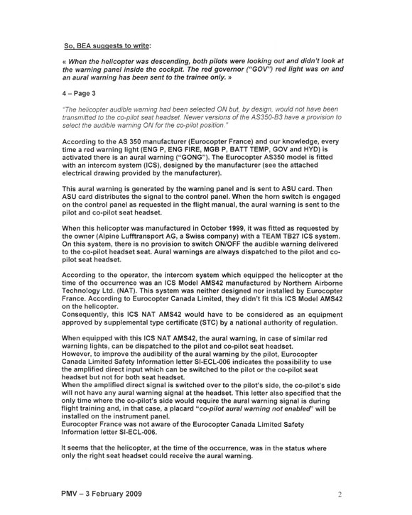
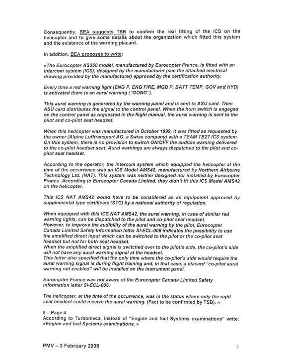
The Eurocopter AS 350 model, manufactured by Eurocopter France, is usually fitted with an intercom system (ICS) designed by the manufacturer and approved by the certification authority. Every time a red warning light (ENG P, ENG FIRE, MGB P, BATT TEMP, GOV, and HYD) is activated there is an aural warning ("GONG"). When the horn switch is engaged on the control panel as recommended in the flight manual, the aural warning is sent to the pilot and co-pilot seat headsets.
When this helicopter was manufactured in October 1999, it was fitted (as requested by the owner at the time) with a Team TB27 ICS system. On this system, there is no provision to switch off the audible warning delivered to the co-pilot headset.
The intercom system installed at the time of the occurrence was a model AMS42, manufactured by Northern Airborne Technology (NAT) Ltd. No record of this installation was provided. When equipped with this NAT AMS42 ICS, the aural warning, in case of similar red warning lights, can be dispatched to the pilot and co-pilot seat headsets. The operator chose to have the warnings only available to the pilot because passengers often sit in the left cockpit seat. It was reported that such audio alerts can be unnecessarily alarming to them.
This NAT AMS42 ICS did not have a technical standard orders (TSO)Footnote 1 approval, nor was it required. The U.S. Federal Aviation Regulations (FARs) and the CARs do not require an audible warning to be provided and, therefore, there are no specific airworthiness requirements that address audio warnings and that provide detailed guidance for assessment.
In response to a 1995 TSB recommendation (A95-15), Transport Canada issued Advisory Circular (AC) 500-001 Issue 001, dated 20 June 2007, to advocate the provision of audio warnings that can be heard by pilots. The purpose of the AC is to provide guidance for the demonstration of compliance and for assessment and approval to assist in the confirmation of compliance with the applicable requirements of the Airworthiness Manual (AWM) in relation to:
- Cockpit audio alerts and warnings; and
- Switch systems designed to "mute" cockpit speakers, thereby "inhibiting" audio alerts to the flight deck under certain conditions.
In April of 2002, the U.S. Federal Aviation Administration (FAA) assigned four new tasks to the Aviation Rulemaking Advisory Committee (ARAC) under Title 14 of the FAR Part 25/Joint Aviation Requirements (JAR-25), Sec. 25.1322, to develop recommendations that would broaden the current regulations and advisory material to include state-of-the-art flight deck displays and new technologies to aid flight crewmembers in decision making. The regulations remain unchanged, however, and address visual alerting cues only in the form of coloured lights installed in the flight deck.
During the course of this investigation, Eurocopter Canada Limited issued Service Information Letter SI-ECL-006 (dated 28 March 2008) to address recent comments from pilots in the field about the relative volume of the aural warning signal in the pilot's headset. It suggested that to improve the audibility of this signal, the audio control of the NAT AMS42 could be reconfigured so that the direct amplified input is switched over to the pilot's headset. It further advised that for future COMM/NAV modifications on the AS 350 B2, B3, and EC 130 B4 helicopters, the amplified direct signal will be switched over to the pilot's side.
When the amplified direct signal is switched over to the pilot's side, the co-pilot's side will not have any aural warning signal at the headset. The only time when the co-pilot's side would require the aural warning signal is during flight training. For this configuration, the following placard will be installed on the instrument panel: "CO-PILOT AURAL WARNING NOT ENABLED". Eurocopter U.S. and Eurocopter France were not aware of the Eurocopter Canada Limited Safety Information Letter SI-ECL-006.
Both pilots were leaning out of the helicopter to observe the longline at the time of the reduction in power and could not recall hearing any audible warning or seeing any warning lights. The aural warning at the co-pilot seat was not enabled and the warning placard was not installed.
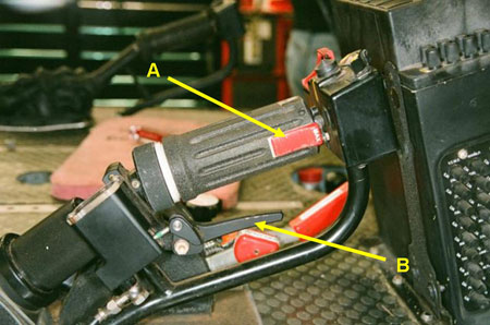
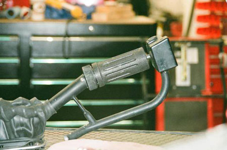
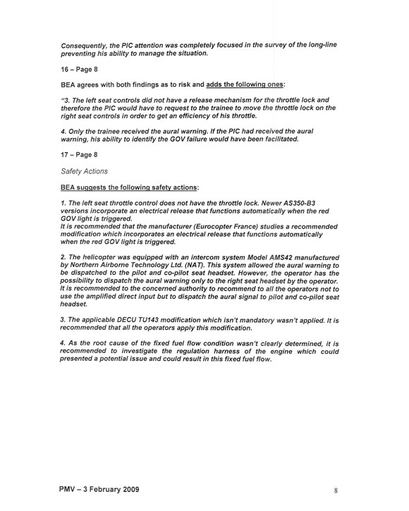
The controls installed to accommodate a second pilot in the left front seat were different from the right seat position. The normal pilot position (right) controls have a collective lever that incorporates a throttle lock referred to as flight notch in the RFM (see Photo 1). In case of emergency, releasing the lock allows manual fuel control operations at all power settings. The left seat throttle control does not have the lock (see Photo 2). Newer versions of the AS 350-B3 incorporate an electrical release that functions automatically when MANUAL MODE is selected, or when the red GOV light is triggered.
The helicopter's cargo hook is normally released by electric push buttons on both cyclic controls, but they were not armed during the accident flight. While there is a hydro-mechanical manual cargo release, it is only incorporated in the right side collective control. The longline was not released during the emergency.
Engine and Fuel System Examinations
The engine (a Turbomeca Arriel 2B, serial number 22083, total time since new (TTSN) of 2304.9) along with its hydro-mechanical metering unit (HMU) and DECUFootnote 2 were removed from the airframe for further evaluation at an engine test facility.
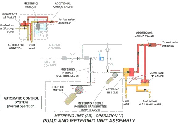
The DECU monitors and controls engine operations. The Arriel 2B utilizes a single-channel digital engine control system with a redundant electrical supply from the engine alternator and aircraft battery. It is programmable and interfaces between the aircraft and system components. It captures and retains events that exceed certain pre-set parameters and stores this information in memory. In the event of a level three failure, the DECU freezes the stepper-motor (which adjusts the fuel metering valve), resulting in a fixed fuel flow condition. The faults previously noted from the VEMD were compared to the data retained by the DECU.
The DECU data confirmed that a fault occurred about 30 minutes into the flight. The fault is referenced in Turbomeca Arriel 2B Maintenance Manual Task 71-00-06-817-854-A01 as a fuel valve resolver and stepper-motor failure. This manual provides troubleshooting instruction for this failure and three possible causes:
- Pump and metering unit assembly (HMU)
- EECU/DECU
- Control harness
When the engine arrived at the test facility, an inspection was conducted to determine the general condition and feasibility of conducting a test run. Some contamination of the HMU fuel filter was noted; it had accumulated about 450 hours of its 600-hour in-service life. Fuel and oil samples were recovered for analysis. Some debris from the fuel sample was analyzed at JET-CARE International Inc. The results of this study were examined as part of TSB Laboratory report LP 020/2008 - Test and Analysis of DECU. Both the engine oil filter and the HMU fuel filter were removed and retained for further analysis. This analysis revealed no materials inherent to the HMU and determined that its filter was performing its function as it had retained the contamination observed during its removal.
The engine was installed in the test cell with its original HMU and electrical harnesses. There are two harnesses - the control and monitoring harness and the regulation harness. Both harnesses are plugged into the DECU on one side and into sensors and the HMU on the other. The control and monitoring harness transmits signals dedicated to DECU control and monitoring. The regulation harness transmits signals dedicated to DECU regulation functions.
It was operated in both speed and position/automatic flight modes. It was capable of producing full power. The engine was tested through transients, engine sensors of accelerations and decelerations, bleed valve opening and closing points, and alternator function. The manual/auxiliary system function of the fuel control performed without fault. The HMU functions were tested and also performed with no fault indicated. The performance of the engine in the test cell did not indicate any issues with its electrical harnesses.
The engine had been prepared for the test cell with slave oil and fuel filters installed (from the test cell group). These were not new filters because it is a Turbomeca policy and the practice of the test cell engineers to re-use these filters several times; however, they are inspected after each engine test run. After the engine testing, chip plugs were examined and found clean. Fuel and oil filters were checked; some very fine shiny magnetic debris was found in the HMU filter housing. The probability that the HMU was generating this metal was considered because the filter should have been clean. It was reported that this filter had been used on six previous occasions.
Turbomeca U.S. advised that more in-depth testing could be performed in France, as it was not possible to test all components as an assembly (DECU and engine) in its test cell. The HMU could be tested and/or disassembled to check for possible scoring and/or metal generation. The investigation was re-focused on the DECU and HMU in France. Thales manufactures this DECU for Turbomeca.
Recently, the French Bureau d'Enquêtes et d'Analyses (BEA) investigated an Agusta A109E helicopter with an Arrius 2K1 engine that experienced a stepper motor fault resulting in a fixed fuel flow condition (BEA Report n-du080711_cal01/ - 11 July 2008). The regulation harness manufactured by Aquitaine Electronique, part number 0319768200, was found to conceal internal corrosion and signs of electrical arcing considered to be at the root cause of the stepper motor fault. Also, Turbomeca advised of an examination of a Eurocopter AS 350 B3 with an Arriel 2B engine operated in Australia that revealed a regulation wiring harness with a continuity discrepancy considered again to have resulted in a fixed fuel condition.
Continued Examination of Engine Fuel Controls at Turbomeca France and Thales Facilities
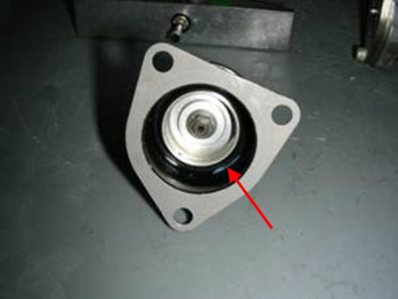
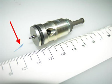
A detailed disassembly and examination of the HMU by Turbomeca, Thales, the BEA, and TSB Laboratory personnel revealed the presence of a contaminant within the HMU fuel channels. This contaminant was determined to be a small sliver of O-Ring seal material resting in the delta P diaphragm chamber (see Photo 3 and Photo 4). There was no metal generated within this component. The stepper motor and DECU were extensively tested individually with no results that could explain the condition experienced. A detailed diagram of the metering unit assembly is provided at Appendix A.
The TSB Laboratory investigation determined that the portion of blue O-ring was not part of the O-rings installed on the system and therefore had likely been introduced into the system during previous maintenance work or during the initial manufacture of the system.
Control and Monitoring Harness, and Regulation Harness Examination
A follow-up examination of the engine wiring harnesses (control and monitoring harness, and the regulation harness) was deemed advisable in light of the two recent occurrences confirmed by Turbomeca U.S. and despite the uneventful earlier results with the subject harnesses in the engine test cell. TSB Laboratory report LP 020/2008 was amended to show this activity. The wiring harnesses showed no relevant anomaly and no corrosion on connector wires and pins.
Maintenance History
All maintenance, logbooks, and applicable DECU modification updates were accomplished, except for software update TU143. That update changed the DECU through:
- improvement of logic concerning pitch loss tolerance;
- the addition of a reset function for the cycle counters;
- the incorporation of a rundown time counter and failure context storage; and
- updating of the N1, N2, and alternator failure detection logics.
HMU / (HP Fuel Pump) part number 0292858770, serial number 174B, was removed on two occasions for unspecified maintenance actions. It was overhauled on 09 March 2004 and returned to service with time since overhaul (TSO) of 0.0 hours. It was installed on engine serial number 22083 on 20 September 2004 with TSO of 907.04 hours. On 26 January 2005, the HMU had accumulated TSO of 1294.3 hours, at which time pressure switch part number 9550172000 was replaced. At the time of the accident, the HMU had accumulated a total TSO of 1393.8 hours. It has a 3000 hour life.
On 06 June 2002, Eurocopter issued Service Letter No. 1556-71-02, which addressed the failures of the fuel control unit as a result of the "discrepancy between the theoretical and effective positions of the stepper motor in the fuel metering unit". As a precaution, Eurocopter asked operators to completely shut down the engine prior to refuelling to "reduce the suspected risk of discrepancy by resetting the computer more frequently. The computer is automatically reset at each engine shutdown." The service letter also stated that Turbomeca had issued Service Bulletin 292 73 2066, which provided data for installing software modification TU66C, that "...basically increases FADECFootnote 3 tolerance to the rotor pitch drop phenomenon... Once modification TU66C is introduced, the prohibition of refuelling while the engine was running is no longer necessary."
On 17 April 2004, Turbomeca issued Service Bulletin (SB) 292 73 2076/TU76, titled Hydro-mechanical Metering Unit (HMU)/Rack is guided inside the fuel metering unit body/Incorporation of modification TU 76. The purpose of the bulletin was to "...eliminate a possible cause of losses of actuator pitch which could lead to a transition into manual mode." The operator was provided instructions to remove the existing HMU and install a modified HMU. This modification included a longer stepper motor rack and a modified cover so the new rack would fit. HMU / (HP Fuel Pump) part number 0292858770, serial number 174B is post TU76 (SB 292 73 2076).
Analysis
While the safety concerns addressed in Eurocopter Service Letter No. 1556-71-02 and Turbomeca Service Bulletin (SB) 292 73 2076/TU76 were initially considered as possible contributing factors, further investigation determined that these issues had not contributed to the occurrence.
A sliver of O-Ring material found in the HMU fuel channels could have obstructed the fuel metering valve. It was not large enough to completely obstruct the orifice; however, it could impede the movement of the valve if it were to try and close as the sliver was wedged between the needle and the orifice. This could result in a differential between the resolver and stepper motor positions and cause a fixed fuel flow condition. The governor could not deliver the increased fuel flow required to maintain the high hover and the helicopter descended.
The left seat controls did not have a release mechanism for the throttle lock. Therefore, the PIC was unable to initiate manual control of the throttle. There was insufficient fuel flow to provide the power necessary to arrest the rate of descent and a hard landing ensued.
Both pilots were leaning out to observe the longline at the time of the fixed fuel flow condition and did not see the GOV light displayed on the warning panel. Additionally, due to his sitting in the left seat, the PIC did not receive the aural warning that accompanies activation of a warning light. The PIC's ability to manage the emergency was hampered by a lack of audio warning provided to the left seat pilot and the lack of a throttle lock release mechanism on the left collective.
Because the external cargo hook was not armed during the training exercises, the PIC would not have been able to jettison it. Both pilots were experienced in longline operations but did not think of releasing the longline; the PIC's attention was completely focused on landing the helicopter during this emergency. Even though the longline did not cause this accident or add to the helicopter's damage, there is a risk that if left attached during an emergency it could get caught in terrain obstacles, alter the attitude of the helicopter, and hamper its control.
The trainee pilot was not sufficiently familiar with the aircraft to act on the emergency and the crew had not briefed on sharing information or duties in this event. There was insufficient time to coordinate the necessary actions to ensure a safe landing.
The following TSB Laboratory report was completed:
- LP 020/2008 – Test and analysis of digital engine control unit (DECU)
This report is available from the Transportation Safety Board upon request.
Findings
Findings as to causes and contributing factors
- The fuel control unit did not deliver the increased fuel flow required to maintain the high hover, and the helicopter descended and a hard landing ensued. The contaminant found in the hydro-mechanical metering unit (HMU) could have obstructed the fuel metering valve, resulting in a fixed fuel flow condition.
- The left seat controls did not have a release mechanism for the throttle lock and therefore the pilot-in-command (PIC) was unable to initiate manual control of the throttle and arrest the rate of descent.
- Both crew members were looking outside and did not see the warning light. The PIC's ability to manage the emergency was hampered by the lack of an audio warning in the left seat position.
Findings as to risk
- The external cargo hook was not armed during the exercises and the pilot-in-command (PIC) was not able to jettison the longline. There is a risk that if left attached during an emergency it could get caught in terrain obstacles, alter the attitude of the helicopter, and hamper its control.
- In training operations where special attention is not given to briefing on duties and coordination in the event of an emergency, there is a heightened risk that helicopters may not be landed safely.
Safety action
Safety action taken
Prism Helicopters undertook the following corrective actions:
- a) Added "ARM CARGO HOOK" to the AS 350B3 Engine Pre-Start Cockpit Checksheet. This will ensure the pilots do not miss the arming of the cargo hook prior to external load operations.
b) Questions have been added to the appropriate operations exams regarding external load operations, specifically the "arming of cargo hooks". - Prism has enhanced its standardized pre-flight briefing prior to training and evaluation flights to clarify the duties and responsibilities of crew members regarding all parts of the training, including real emergencies.
- The aircraft instrument panel was placarded with "CO-PILOT AURAL WARNING NOT ENABLED" as per Eurocopter Canada Service Information Letter dated 28 March 2008.
- The governor aural warning signal on the aircraft was checked for adjustment for maximum volume available.
This report concludes the Transportation Safety Board's investigation into this occurrence. Consequently, the Board authorized the release of this report on .
