Double engine power loss and forced landing
Fugro Aviation Canada Limited
CASA C-212-CC40, C-FDKM
Saskatoon, Saskatchewan
The Transportation Safety Board of Canada (TSB) investigated this occurrence for the purpose of advancing transportation safety. It is not the function of the Board to assign fault or determine civil or criminal liability. This report is not created for use in the context of legal, disciplinary or other proceedings. See Ownership and use of content. Masculine pronouns and position titles may be used to signify all genders to comply with the Canadian Transportation Accident Investigation and Safety Board Act (S.C. 1989, c. 3).
Summary
At 1503 Central Standard Time, the Construcciones Aeronauticas SA (CASA) C-212-CC40 (registration C-FDKM, serial number 196) operated by Fugro Aviation Canada Ltd., departed from Saskatoon/Diefenbaker International Airport, Saskatchewan, under visual flight rules for a geophysical survey flight to the east of Saskatoon. On board were 2 pilots and a survey equipment operator. At about 1814, the right engine lost power. The crew shut it down, carried out checklist procedures, and commenced an approach for Runway 27. When the flight was 3.5 nautical miles from the runway on final approach, the left engine lost power. The crew carried out a forced landing adjacent to Wanuskewin Road in Saskatoon. The aircraft impacted a concrete roadway noise abatement wall and was destroyed. The survey equipment operator sustained fatal injuries, the first officer sustained serious injuries, and the captain sustained minor injuries. No ELT signal was received.
1.0 Factual information
1.1 History of the flight
1.1.1 Pre-flight preparation
The aircraft and crew conducted a survey flight on the morning of the occurrence, and the aircraft operated normally throughout the flight. After that flight, an aircraft maintenance engineer employed by Fugro Aviation Canada Limited (Fugro) fuelled the aircraft with 1703 litres of Jet A fuel.
Before the occurrence flight, the pilots conducted a pre-flight inspection of the aircraft during which all annunciator panel lights were confirmed to be operational. The single red line (SRL)Footnote 1 and torque/temperature limiting (TTL)Footnote 2 systems were also confirmed to be operational. The pilots calculated the aircraft weight and balance using a spreadsheet on a laptop computer.
The captain occupied the left seat and the first officer (FO) the right seat. Prior to engine start, the crew reset the fuel totalizersFootnote 3 to zero. Both engine starts were normal. The flight departed from Saskatoon at 1503.Footnote 4
1.1.2 Survey flight
The area to be surveyed was within 30 nautical miles (nm) to the east of Saskatoon over generally flat terrain at an elevation of 1700 to 1800 feet above sea level (asl). There were a number of towers and electrical lines in the area.
Initial survey equipment calibration was done at 5500 feet asl, followed by descent to 400 feet above ground level (agl) for the survey. The aircraft was not equipped with an autopilot and the pilot flying maintained survey altitude using visual reference and the radar altimeter.
The first 3 hours of the flight were completely normal. The pilots transferred control hourly and, during the occurrence, the FO was the pilot flying. The flight was northbound on the last north-south line of the survey block with about 10 nm to complete.
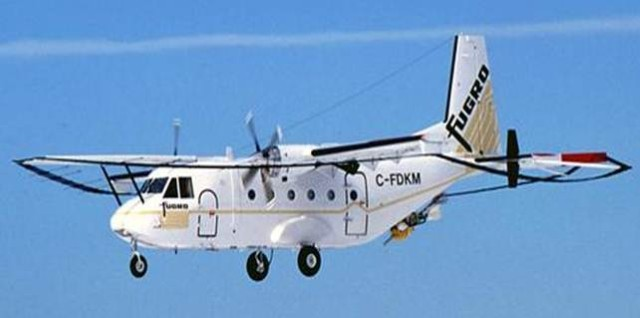
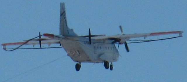
The aircraft was flying straight and level in the survey configuration with flaps up and the 2 survey sensors, or birds, (Photo 1 and Photo 2) deployed behind and below the aircraft. Altitude was 2300 feet asl, indicated airspeed was 130 knots (KIAS) with engine power stable at 99.7% rpm and 60–65% torque. The left and right normal fuel booster pumps were on, the fuel crossfeed was closed, and both left and right fuel pressure instruments were indicating normal readings. No annunciators or warning lights were illuminated and there were no abnormal engine instrument indications. None of the engine control levers had been moved recently. Fuel flow was 340 pounds per hour (pph) on the left engine and 360 pph on the right engine.
1.1.3 Right engine power loss
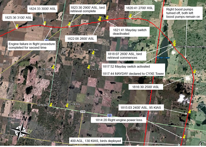
At about 1814:20 (Appendix A), the aircraft experienced a shudder from the right engine just before it smoothly spooled down. The propeller rotation slowed and the aircraft yawed. The right engine torque fell below 20%. The crew confirmed that the right engine had lost power.
1.1.4 Response to right engine power loss
The captain set maximum power on the left engine (100% torque, 100% rpm and exhaust gas temperature [EGT] greater than 600 °C and less than the limit of 650 °C) and verbally advised the FO that maximum power was set. All engine indications for the left engine remained normal.
The FO applied pressure to the left rudder pedal to counter the yaw and adjusted the rudder trim to reduce, but not eliminate, the rudder pedal force required. The rudder trim was not set to full travel. The FO requested the captain assist on the left rudder pedal and the captain did so. This method was used for the remainder of the flight, and the rudder trim setting remained unchanged for the remainder of the flight.
The FO banked the aircraft 5° left to help maintain directional control, and maintained the left bank until the left engine lost power later in the flight. The ball on the turn and slip indicator was steady at well left of centre.
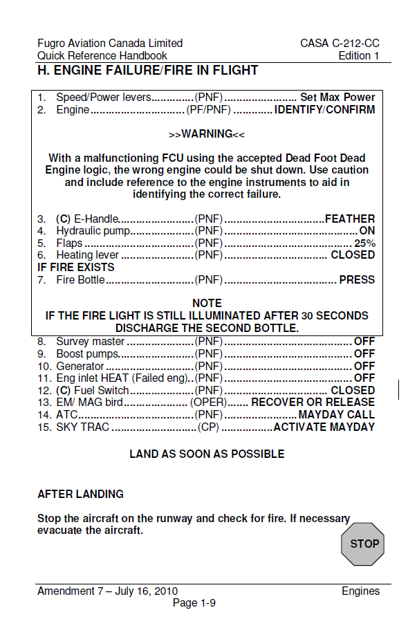
The captain began to action the memory items for the engine failure in flight procedure (Appendix B). When the captain called for the FO to confirm the right emergency shutdown lever, the FO halted him before the lever was moved. The FO then turned on the left and right auxiliary fuel booster pumps; both the left and right normal booster pumps were already on. After a couple of seconds, the FO confirmed the right emergency shutdown lever and the captain moved it to the feather position. The propeller feathered, and the captain completed the remaining memory items of the procedure, including "hydraulic pump on" and setting the flaps to 25%. The flaps stayed at 25% for the remainder of the flight. After completing the memory items, the captain reset the master caution light.
The FO concentrated on aircraft control because performance was marginal. Airspeed decreased substantially to less than 95 KIAS.
As the FO had more experience on the aircraft than the captain, the pilots agreed to let the FO continue as pilot flying. The captain would continue with the checklists and radio communications with air traffic control (ATC).
The crew decided that, before recovering the sensor birds, the survey equipment operator would remain seated until they had confirmed the aircraft would climb. If necessary, the birds would be released. Either recovery or release would require the survey equipment operator to get out of his seat and move about the cabin to operate the required equipment.
At 1816:30, the flight had climbed to 2500 asl, and the FO turned toward the northwest. This permitted the flight to proceed closer to Saskatoon while avoiding a group of towers immediately to the west.
The captain then referred to the quick reference handbook (QRH) for the engine failure in flight procedure checklist, confirmed all memory items had been carried out, and completed the remaining items on the checklist. Both the right normal and right auxiliary fuel booster pumps were turned off; the left normal and left auxiliary fuel booster pumps remained on.
At 1817:44 the captain notified the Saskatoon control tower of the situation with a MAYDAY call, advising they had lost power on one engine and were returning to Saskatoon. The aircraft was equipped with an on-board SkyTrac system, which transmitted position data and other aircraft information during the flight via a satellite link. The FO activated the emergency MAYDAY function of the SkyTrac system.
After completing the checklist, the captain kept his left hand on the control column, right hand on the power levers, and feet on the rudder pedals. He was ready to assist the FO or take control if necessary, but was not applying any pressure to the controls other than the left rudder pedal.
The crew did not attempt to restart the right engine; their priorities were aircraft controllability, climbing to higher altitude, recovering the birds, and returning to Saskatoon.
After the engine failure in flight checklist had been completed, the indicated right fuel pressure increased to and remained at 50 pounds per square inch (PSI). This was a result of high ambient nacelle temperature causing expansion of the trapped fuel in the lines between the closed firewall fuel valve and the fuel control unit. The fuel crossfeed was closed at the time and the fuel pressure on the left engine remained normal.
1.1.5 Bird retrieval
By 1818:07, the aircraft had climbed to 2600 feet asl and accelerated to about 99 KIAS, and the pilots had instructed the survey equipment operator to recover the birds. The survey equipment operator got up to do so. The recovery process took 4 to 5 minutes, during which time the flight initially continued climbing to the northwest to avoid the towers to the west and then turned westward.
The captain referred to the QRH a second time to verify that all steps in the engine failure in flight procedure had been completed. During this period the MAYDAY function of the SkyTrac system was unintentionally deactivated.
By about 1823:30, bird recovery was complete, and the survey equipment operator returned to his seat and strapped in. The flight had climbed to 2900 feet asl, and airspeed was about 100 KIAS.
1.1.6 Preparation for landing
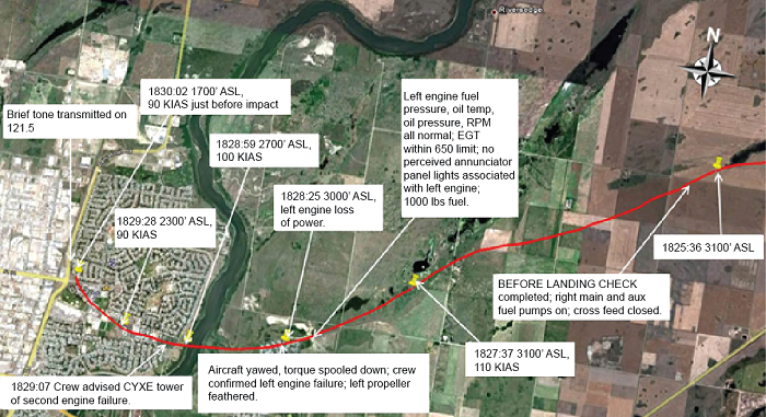
As the flight continued toward the Saskatoon airport, rather than optimizing climb rate the crew chose to slowly increase airspeed to provide an increased margin of safety above the minimum control speed. At 1825:36 (Appendix C), the flight reached 3100 feet asl (about 1400 agl), the maximum altitude following the right engine power loss.
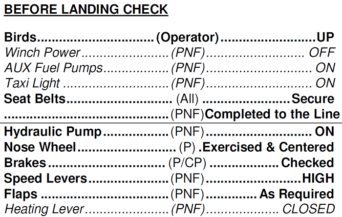
At about 1826, the crew completed the portion of the "Before landing check" above the line (Appendix D). The right normal and right auxiliary fuel booster pumps were turned on during the before landing check. Because the nose wheel steering tiller is on the left side of the cockpit, the pilots discussed the need to transfer control after landing.
By 1827, airspeed was about 105 to 110 KIAS, and both pilots had visual contact with the runway. The FO's plan was to fly a high steep approach, and he had not yet reduced the left engine power lever setting for the approach.
At 1827:11 the tower cleared the flight to land on runway 27.
The FO still had the aircraft banked 5° left with the rudder pedal at full deflection, and the ball in the turn and slip indicator was displaced about halfway to the left.
The captain still had his left hand on the control column, right hand on the power levers, and feet on the rudder pedals, but was not applying any pressure to the controls. The captain was following through on the controls and was ready to assist or assume control if necessary. The FO's hands were on the control column.
Neither pilot observed the fuel level left tank or fuel pressure left engine annunciators illuminate after the engine failure in flight procedure had been completed for the right engine power loss. The FO did not look at the master caution light. The captain did not see the master caution light illuminate after it had been reset following completion of the engine failure in flight procedure for the right engine power loss.
The captain was frequently scanning the left engine instruments after the right engine had lost power. He observed that:
- there were no abnormal indications;
- there were no annunciator panel lights associated with the left engine;
- the left fuel pressure light was not illuminated;
- the left fuel pressure indication was stable and not fluctuating;
- there were no low fuel warnings; and
- fuel flow was stable.
1.1.7 Left engine power loss
At about 1828:25, airspeed was 105 KIAS or greater when the left engine smoothly lost power with no surging. The captain was looking at the engine instruments at the time, and all indications had been normal. Torque and rpm were 100% with no fluctuations; EGT was slightly greater than 600 °C and less than the 650 °C limit; fuel pressure, oil temperature, oil pressure, and fuel flow were all normal. The captain observed the torque indicator smoothly and rapidly decreasing from 100% to 20% within a couple of seconds. The captain did not observe any of the other engine instruments as the loss of power occurred.
Both pilots could feel the aircraft decelerate when the engine lost power. As the torque decreased to 20%, the captain could feel the FO changing the position of the rudder pedals. Both pilots could feel the aircraft yawing to the left, and it was clear to both that the left engine had lost power. Airspeed at the time was about 110 KIAS, and the altitude was 3000 feet asl (about 1300 feet agl). The captain verbally advised the FO that the left engine had lost power.
1.1.8 Forced landing
Both pilots immediately concluded the flight would not reach the runway, and the captain pointed out a large street to the FO as a feasible forced landing site and the FO concurred. Neither pilot could see any better alternative.
The captain immediately reached for the left emergency shutdown lever and called for the FO to confirm the captain had the correct lever. The FO confirmed it and the captain moved the left emergency shutdown lever to feather.
The FO turned the aircraft toward the street. At 1829:07, the captain advised the Saskatoon tower controller of the second loss of power and indicated that they would be landing on the street.
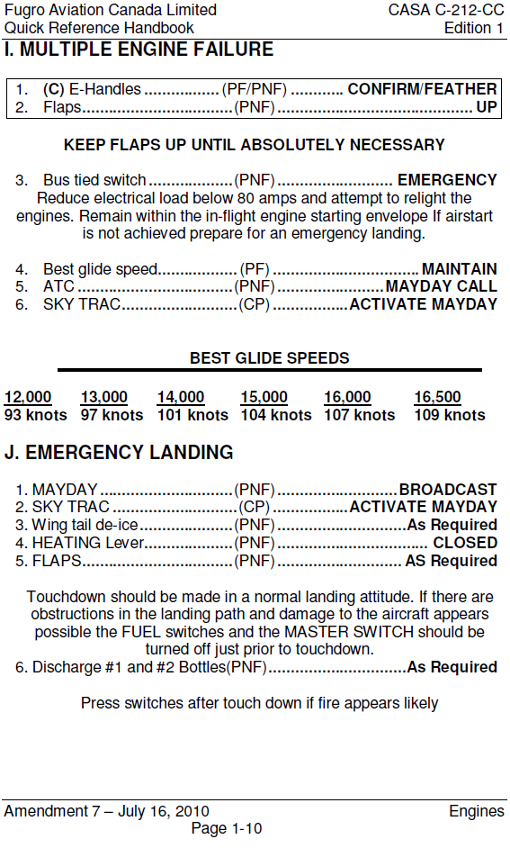
Because of the low altitude and limited time to select and fly to a suitable forced landing site, the crew elected to leave the flaps at 25% and did not complete any other emergency checklist actions or refer to the QRH (Appendix E).
The FO maintained control of the aircraft throughout the descent. Airspeed slowed initially to 100 KIAS and later to 90 KIAS. The goal was to control the descent and impact, with a minimum airspeed of 90 KIAS to prevent a departure from controlled flight. The stall horn did not sound although the FO did observe the stall warning light flashing. The captain continued to back up the FO on the controls.
The pilots observed traffic on the road. They revised the intended touchdown site to the grass beside the road, to the right of the traffic and light poles and the left of what they perceived as a frangible fence.
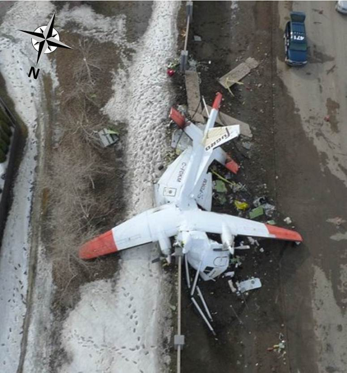
Late in the descent the pilots identified that the fence was actually a noise abatement wall. The FO concluded that the flight could not be extended beyond the noise abatement wall and advised the other crew members. The aircraft landed astride the wall at 90 KIAS (Photo 3). When the aircraft came to a stop, the captain turned off the batteries and the master switch and pressed the cockpit engine fire extinguisher buttons.
1.2 Injuries to persons
| Crew | Passengers | Others | Total | |
|---|---|---|---|---|
| Fatal | 1 | – | – | 1 |
| Serious | 1 | – | – | 1 |
| Minor/None | 1 | – | – | 1 |
| Total | 3 | – | – | 3 |
1.3 Damage to aircraft
The aircraft was destroyed by impact forces.
1.4 Other damage
Property damage was limited to the noise abatement wall and landscaping in the vicinity of the wall, with minor environmental damage from hydraulic and battery fluid spillage.
1.5 Personnel information
Records indicate that both pilots were certified and qualified for the flight in accordance with existing regulations. There was nothing found to indicate that either pilot's performance was degraded by physiological factors. Both flight crew members work/rest schedules were such that fatigue is not considered a factor in this occurrence.
The captain held an Airline Transport Pilot Licence, a glider pilot licence, and a category 1 medical certificate valid until 01 October 2011. The captain had accumulated approximately 7400 hours of total flight time prior to the occurrence with approximately 75 flight hours on the CASA C 212.
The FO held an Airline Transport Pilot Licence, a glider pilot licence, and a category 1 medical certificate valid until 01 July 2011. The FO had accumulated approximately 7800 hours of total flight time prior to the occurrence with approximately 1800 flight hours on the CASA C-212. The FO was certified and qualified as a CASA C-212 captain. Fugro practice is for pilots to alternate seats and pilot-in-command duties weekly, and it was the FO's week to fly from the right seat as FO.
No simulator is available for the survey configuration of the CASA C-212, and the captain and FO received all their training in the aircraft. Training for one engine inoperative with the birds deployed cannot be done in the aircraft, because the birds cannot be deployed without a survey equipment operator and simulated engine failures cannot be conducted with an equipment operator on board.
Despite these factors, Fugro does provide pilots with training in the CASA C-212 for engine failure in flight during survey operations, albeit without the birds deployed. To simulate the additional drag of the birds, aircraft performance is reduced by conducting the training at 5000 to 8000 feet agl at the maximum aircraft weight permitted for ambient conditions. The training exercise is initiated with a simulated engine failure, with the crew carrying out the engine failure in flight procedure and climbing 500 to 1000 feet above the altitude at which the exercise began. Applicable checklists are then completed, and the exercise concludes with a return to the airport for a landing with one engine simulated inoperative. Training records show that both the captain and the FO received this training.
While multiple engine failure cannot be practiced in the aircraft, the situation is discussed during training.
1.6 Aircraft information
1.6.1 General
| Manufacturer | Construcciones Aeronauticas SA |
| Type and model | C-212-CC40 |
| Year of manufacture | 1981 |
| Serial number | 196 |
| Special Certificate of Airworthiness – Restricted, issue date | 2004-06-01 |
| Total airframe time | 21292.7 hrs |
| Engine type (number of) | Garrett TPE331-10R-511C (2) |
| Propeller/rotor type (number of) | Hartzell HCB4MN-5AL (2) |
| Maximum allowable take-off weight | 7700 kg |
| Recommended fuel type(s) | Jet A, Jet A-1, JP-8, Jet B, JP-5 P4, Jet A, Jet A1sss |
| Fuel type used | Jet A |
The aircraft (Photo 1) was authorized for use to conduct aerial geophysical surveys under the provisions of a Special Certificate of Airworthiness – Restricted. The restricted classification was assigned because the aircraft type certificate was in the restricted category and also because the aircraft had been modified in such a manner that it no longer complied with the original certificate. See section 1.6.3 regarding the modifications.
Records indicate that the aircraft was certified, equipped, and maintained in accordance with existing regulations and approved procedures. The aircraft underwent an inspection, which primarily focused on the airframe with a few engine-related requirements, as well as an inspection of the right engine on 03 Dec 2010, approximately 98 flight hours prior to the occurrence.
On the morning of the occurrence, the aircraft was due for other inspections, including one of the left engine, within 8.4 hours. These inspections had been largely completed and the completion of the remaining inspection items and final signoff had been extended 10 hours in accordance with the Fugro Maintenance Control Manual. Maintenance personnel had recorded the completed inspection items on the applicable tally sheets. Items that were complete included replacement of the wing fuel system ejector pump filters and functional tests of fuel system valves and booster pumps.
1.6.2 Engines and propellers
The engines had an approved overhaul period of 7000 hours. A spectrographic oil analysis program (SOAP) was an integral part of the operator's maintenance program. The SOAP required that oil samples be taken every 200 hours and sent to an independent lab for analysis.
Both engines were equipped with magnetic chip plugs in the reduction gear housing. When the contact of a chip plug is shorted to ground by metal particles the corresponding chip detector segment of the annunciator panel will illuminate.
The engines on C-FDKM were not equipped with an auto-ignition system. Such a system is not normally installed on these engines on the CASA C-212-CC40.
The aircraft was equipped with propellers which rotate counter-clockwise as viewed by the crew. Because of the counter-clockwise rotation, the right engine is the critical engine.Footnote 5 “The critical engine is the engine, the failure of which would most adversely affect the performance or handling qualities of an aircraft”.Footnote 6
1.6.3 Aircraft modifications
In 1989, the aircraft was modified in accordance with supplemental-type approval SA86-9 “Installation of Electro-Magnetic (EM) Survey System and Associated Stability Finlets”. The EM survey system included a loop comprising 6 heavy-gauge cables that surrounded the aircraft. The cables were secured at structural points at each wing tip, at tubular extensions on the nose, and at an aft fuselage extension. The main batteries were relocated from the left landing gear sponson to a more forward location in the main cabin for centre of gravity reasons. The auxiliary battery remained in its original location in the sponson. Finlets were installed mid-span on the upper and lower surfaces of each horizontal stabilizer.
As a result of SA86-9, the performance characteristics of the modified aircraft differed from the unmodified aircraft as manufactured by CASA. See section 1.6.7 for information regarding aircraft performance.
The unmodified CASA C-212 is required to have rudder control surface movement range of +27.5° ± 1° to −27.5° ± 1°.Footnote 7 After modification, in accordance with SA86-9, the rudder control surface movement range is required to be +20° to −20°.Footnote 8
During development of SA86-9, the contractor and Transport Canada determined the CASA C-212, with the EM system installed, would not meet the certification requirements for directional stability. Consequently, stability finlets and a rudder limitation were installed to bring performance within the directional stability requirements.
Transport Canada type certificate A-147 prescribes the conditions and limitations under which the modified CASA C-212-CC40 meets the standards of airworthiness required by the Canadian Aviation Regulations.Footnote 9 This type certificate was originally approved 29 August 1986. Regarding the basis of certification, the certificate states that:
- special performance conditions apply with respect to the Magnetic Loop/Finlets modification contained in letter 5010-10-375 (ABP/A) to Field Aviation dated May 8, 1986. Ref. Supplemental Type Approval SA86-9;
- all aircraft must include the incorporation of supplemental type approval SA86-9 for the magnetic loop and finlets and must be operated in accordance with the appropriate DOT approved Flight Manual Supplement.
SA86-9 also included the installation of a geophysical sensor bird, a winch, and a stowage rack. The bird could be deployed behind and below the aircraft, and, when recovered, was stowed in the rack located on the exterior surface of the aircraft cargo door. In 1997, a further modification added a second sensor bird and winch system in accordance with LSTA O-LSA-96-0139/D. In 2004, a new bird rack was installed in accordance with LSTA C-LSA4-108D.
Other modifications included improvements to the survey equipment operator seat that added a shoulder harness in 2004 and a headrest in 2006.
At the time of the occurrence, the emergency procedure to release the birds was for the survey equipment operator to use a pair of wire clippers to manually cut the cables. The pilots had no means of jettisonning the birds from the cockpit.
1.6.4 Fuel system
Each wing, outboard of the engine nacelle, houses 2 integral fuel tanks located between the forward and rear spars. The lower surface of the wing has no dihedral, so the bottoms of the fuel tanks are flat in the span-wise direction.
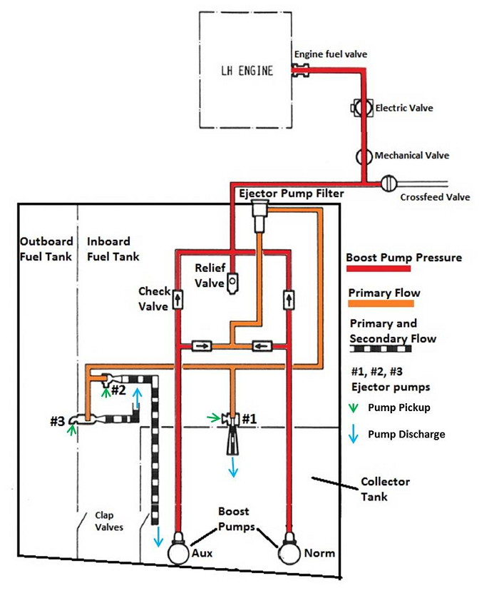
The left and right wing fuel systems are identical but independent. A crossfeed line with a mechanical valve controlled from the cockpit permits fuel from either wing to be supplied to the engine on the opposite wing (Figure 1). Throughout the flight, the fuel crossfeed valve remained closed. Normal operating procedures and the engine failure in flight procedure (Appendix B) did not require it to be opened.
The capacity of each inboard and outboard tank is 719 and 299 litres respectively. The aircraft's total fuel capacity is 2036 litres, of which 1999 litres is usable.
Usable fuel is fuel available for aircraft propulsion. Unusable fuel is fuel remaining in the system and in the tanks when the fuel quantity indicators read zero.Footnote 10
The rear inboard corner of each inboard tank is closed off by a wing rib and a forward baffle to form a collector tank. Fuel is delivered from each collector tank to its respective engine. During normal operation, the collector tanks are kept full, and serve to prevent fuel starvation due to movement and sloshing of fuel in the main tanks. Each collector tank has a capacity of 165 pounds of Jet A fuel (89.7 litres at 1.8397 pounds per litre) with wings level. With the wings banked, capacity will decrease due to spillage into the inboard tank through stringer cut-outs in the collector tank walls on the low side. At 5° bank angle, collector tank capacity is 157 pounds of Jet A fuel (85.3 litres at 1.8397 pounds per litre).
Each collector tank houses a low fuel level switch that illuminates a corresponding (left or right) fuel level warning light on the annunciator panel if the fuel quantity in the collector tank decreases to about 100 pounds. Because of the location of the level switch in the middle of the collector tank, this warning level does not vary significantly with side to side movement of the fuel in the collector tank.
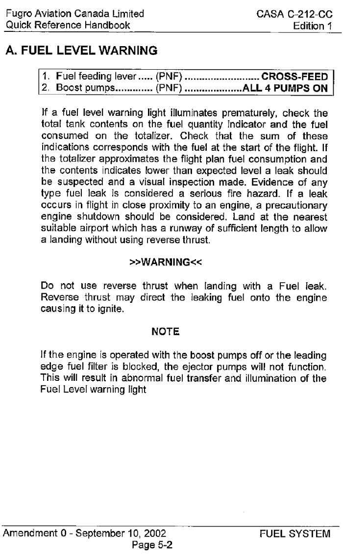
In normal cruise flight, the fuel level warning light illuminates at a fuel quantity sufficient for about 17 minutes of engine operation. At full power, that duration decreases to about 12 minutes. The low fuel level warning system is functionally tested every 1800 hours. Illumination of the fuel level warning light alerts the crew to impending fuel starvation, and requires the crew to complete the fuel level warning procedure (Appendix F). The first step in this procedure is to move the fuel feeding lever to the "crossfeed" position, thereby opening the crossfeed valve.
Two submersed electric fuel booster pumps are installed in each collector tank and deliver fuel through check valves and a series of shut-off valves to provide a positive inlet pressure to the engine-driven fuel pump. At least one booster pump is required to be operating at all times. The booster pumps also provide primary fuel flow to operate 3 ejector pumps in each wing.
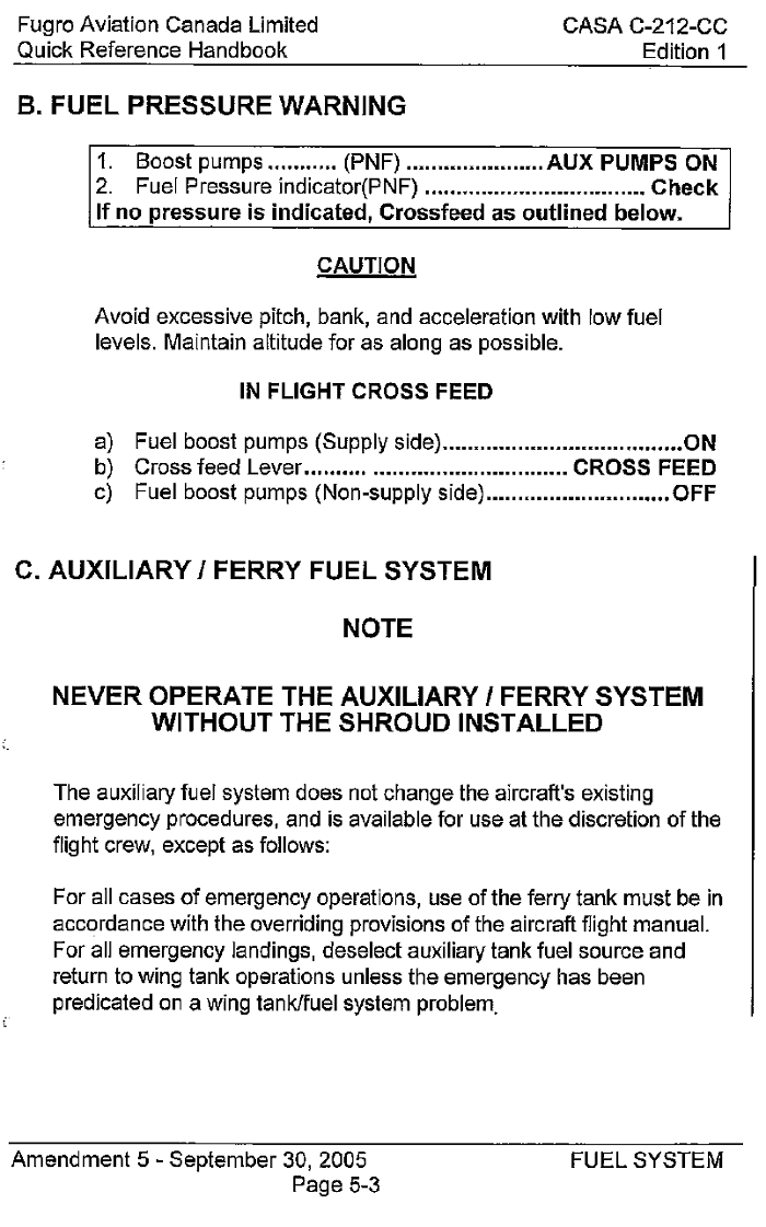
A fuel pressure transmitter and a fuel low pressure switch, mounted on the forward face of each engine firewall, are installed in the fuel lines between the electric firewall valves and the engines. Each fuel pressure transmitter has a corresponding fuel pressure instrument in the cockpit. Each fuel pressure switch will illuminate a corresponding segment of the annunciator panel if fuel pressure drops below 3.5 pounds per square inch (psi). The fuel pressure annunciator will extinguish if the fuel pressure subsequently increases to above 7.0 psi. Illumination of the fuel pressure warning light alerts the crew to impending fuel starvation, and requires the crew to complete the fuel pressure warning procedure (Appendix G).
1.6.5 Ejector pumps
Ejector pumps have no moving parts; they operate using the Venturi principle and incorporate an unscreened inlet pipe situated close to the bottom surface of the fuel tank. "Primary fuel pressure from the booster pump(s) is accelerated through the jet nozzle into the mixing section where its energy is imparted to the secondary fuel which enters the inlet causing the secondary fuel to accelerate. After mixing the combined flow is partially decelerated in the diffuser and static pressure is recovered."Footnote 11 Before travelling to the ejectors the primary fuel flows through a filter element that is replaced on the 1A inspection every 100 hours.
Ejector pump No. 1 is mounted forward of, and pumps fuel directly into, the collector tank. Ejector pump No. 2 is mounted at the outer end of the inboard tank, and also pumps fuel directly into the collector tank. Ejector pump No. 3 is mounted at the inner end of the outboard tank, and pumps fuel into the inboard tank.
Ejector pump No. 1 is larger and has a greater secondary flow capacity than ejector pumps nos. 2 and 3. The flow rates of ejector pump nos. 2 and 3 are the same. Fuel also flows via gravity through "clack" valves from the outboard tank into the inboard tank, and also from the inboard tank into the collector tank.
Fuel system components including the ejectors are subject to a "visual inspection for security and condition" every 4 years. Removal and disassembly is not specified. Performing the "Basic Fuel Distribution System – General Check"Footnote 12 may detect problems with the No. 3 ejector pump. This check does not have a specific interval and is performed as an "Indication Check" or "Booster Pump Operational Check". However, there is no specific test to check the delivery rate of the No. 2 ejector pump.
1.6.6 Fuel distribution
Normal fuel consumption of each engine during cruise was approximately 350 pounds per hour (pph). Calculations and test cell data showed that, at 3000 feet asl and 2 °C and operating at 100% torque and 100% rpm, fuel flow for one engine would have been 500 pph. Additional data provided by the engine manufacturer indicates that the minimum fuel flow to maintain 100% rpm at minimal torque would have been 193 pph, although the engine would not be producing an appreciable amount of thrust in this condition. With fuel flow reduced to 171 pph, propeller rpm would begin to decay.Footnote 13
Takeoff fuel was 3569 pounds of usable fuel. With a standard 50 pound fuel consumption for start, taxi, and takeoff, the ramp fuel before engine start would have been 3619 pounds.
The investigation could not determine whether the fuel was evenly distributed between the wings. Consequently, it is assumed that this was the case and that the usable fuel in each wing at engine start was 1809.5 pounds.
The totalizer recorded that the left engine consumed 1271 pounds of fuel from engine start to the time the left engine lost power. The difference between fuel at engine start and when the left engine lost power, 538.5 pounds, is calculated to be the remaining fuel in the left wing at the crash site.
The time from when the right engine lost power until the left engine lost power was 14 minutes 5 seconds. At 500 pph, the fuel consumed by the left engine during this period would be 117.5 pounds, which, when added to the 538.5 pounds fuel remaining in the left wing resulted in a fuel load of 656 pounds of usable fuel in the left wing at the time of the right engine power loss.
The totalizer recorded that the right engine consumed 1100 pounds of fuel from engine start to the time the right engine lost power. The difference between fuel at engine start and when the right engine lost power, 709.5 pounds, is calculated to be the remaining fuel in the right wing at the crash site.
A sample of fuel obtained from the inboard left wing fuel tank was tested and determined to meet the requirements of the ASTM D1655 and CGSB 3.23-2009 Jet A-1 specifications for density, flash point, freezing point and distillation properties. Visual examination of the fuel sample found it was clear and free of undissolved water. Density of the fuel sample was measured at 825.6 kg/m3 at 15 °C, which was calculated to be equal to 1.8397 pounds per litre at 2 °C. Based on this density, the volume of the 656 pounds usable fuel in the left wing, when the right engine lost power, was calculated to be 356.5 litres.
1.6.7 Aircraft performance
Takeoff weight for the occurrence flight was 15 671 pounds; the maximum take-off weight is 16 976 pounds. The centre of gravity was at moment 235.48, within the limit of 228.83 to 240.91.
As described in section 1.6.3, the aircraft was substantially modified for geophysical surveying. The modifications resulted in substantial changes in aircraft performance. Performance requirements drafted specifically for the project included climb requirements for 100 feet per minute (fpm) 1000 feet above the take-off surface in the take-off configuration with one engine inoperative, and 50 fpm in the enroute configuration with one engine inoperative.
Minimum control speed in the air (Vmca) is the minimum flight speed at which the aircraft is controllable, with a maximum 5° bank angle, when one engine is made suddenly inoperative and the other engine is at takeoff power. For the as-manufactured configuration of the CASA C-212-CC40, Vmca is 85 knots calibrated airspeed (KCAS). With the aircraft modified to the EM survey configuration, supplemental type approval SA86-9 specifies Vmca is 90 KIAS.
Following incorporation of modification SA86-9, C-FDKM was subjected to flight testing to verify it met the standard specified in Transport Canada type certificate A-147. The flight testing was conducted with a cradle for one bird mounted on the exterior of the rear cargo door, but with no bird installed. The flight testing determined the modification had no significant effect on stall speeds published in the CASA airplane flight manual (AFM), and also that aircraft controllability was satisfactory with one engine inoperative at the SA86-9 specified Vmca of 90 KIAS.
The multiple engine failure procedure (Appendix E) includes a chart listing the best glide speed for various weights, with flaps to be kept up until absolutely necessary. The aircraft weight at the time of the forced landing was 13 350 pounds, for which the best glide speed is 98 KIAS.
The stall speed (Vs) for the as-manufactured CASA C-212-CC40 at 13 350 pounds with wings level is 70 KCAS with flaps at 25% and 76 KCAS with flaps up. With 30° bank, Vs increases to 76 KCAS with flaps at 25% and 82 KCAS with flaps up. The AFM supplement for the SA86 9 EM modification specifies that the stall speed chart in the CASA AFM is still applicable.
The SA86-9 AFM supplement includes a chart for one engine inoperative net rate of climb with the inoperative propeller feathered, flaps at 25%, operating engine at maximum continuous power, and 99 KIAS. With the EM loop on the aircraft, at 2 °C, 2500 feet pressure altitude, and 13 350 pounds, the chart shows the rate of climb to be 300 fpm. The LSTA O-LSA-96-0139/D AFM supplement does not specify any performance decrement, despite the addition of a second externally mounted sensor bird which would increase drag even in the stowed position.
Flap 25% is specified for one engine inoperative flight, but flaps up is specified for multiple engine inoperative flight. During certification testing of the modified aircraft, one engine inoperative climb performance was better with 25% flap at 99 KIAS (V2) than with flaps up at 112 KIAS. Therefore, the certificate applicant chose to use the 25% flap configuration for the one engine inoperative climb.
Aircraft performance with the birds deployed was not considered at the time modification SA86-9 and Canadian type certificate A-147 were approved because the expectation was that, in the event of an emergency, the birds would be expeditiously recovered or jettisoned. When deployed, the birds create additional drag which reduces climb rate. There is no information available for one engine inoperative climb performance with either one or both birds deployed.
Analysis of radar data showed the climb rate immediately following the right engine power loss averaged 79 fpm from 1814:20 until 1818:07, when the bird recovery commenced. Bird recovery was complete by about 1823:30, after which the climb rate averaged 95 fpm.
1.7 Meteorological information
The 1800 aviation routine weather report for Saskatoon was as follows: wind 260° true at 12 knots, visibility 15 statute miles with a few high clouds, temperature 3 °C, dew point −1 °C, altimeter setting 29.75 inches of mercury. At survey altitude, outside air temperature was about 2 °C with a westerly wind at about 20 knots.
1.8 Flight recorders
Existing regulations did not require the aircraft to be equipped with flight data or cockpit voice recorders, and no recorders were installed.
1.9 Wreckage and impact information
1.9.1 Wreckage examination
The aircraft was facing north straddling the concrete noise abatement wall on the east side of Wanuskewin Drive. The left wing tip was resting in the northbound curb traffic lane. The cockpit was on the west side of the wall with the wing centre section, aft fuselage and empennage resting on top of the wall. The right wing was on the east side of the wall resting on the ground close to a residential fence line. The bottom of the fuselage and cabin floor had been torn from the aircraft from just aft of the nose gear to the rear cargo door.
The aircraft impacted the wall in a nose level pitch attitude with a slight right bank. The aircraft came to rest in about 98 feet after first contact with the wall. The majority of the impact energy was dissipated by the destruction of the aircraft's lower fuselage, floor structure and the wing centre section.
The emergency locator transmitter (ELT) was located in the wreckage with the antenna severed; no ELT signal had been received. The left main landing gear leg was located on the median of the road approximately 30 feet ahead and 60 feet to the left of the aircraft.
The vertical and horizontal stabilizers and all control surfaces were intact. The left and right wings received light damage. The right flap had been driven up by contact with the wall and the left flap was partially deployed. Due to the disruption of the flap linkages in the wing centre section it was not possible to ascertain what the flap position was prior to contact with the wall.
The propellers were in the feathered position and showed no signs of rotation at impact. One blade of the right propeller had fractured on contact with the wall.
No fuel leaks were evident. All fuel caps were in place. Fuel was visible in each inboard tank. Because each wing sloped downward from the wall to the ground, fuel was slowly migrating to the outboard tanks. After fuel samples were taken from each wing tank, fuel was pumped into a recovery tanker to facilitate wreckage removal.
All 4 engine fire extinguisher guards were up, although the fire extinguishers had not discharged. All 4 fuel booster pump switches were in the on position. The left fuel valve switch was in the open position, and the right fuel valve switch was in the closed position. Examination revealed that the position of the electric firewall fuel valves matched the cockpit switch selections. The main batteries that were mounted in a box behind the cockpit bulkhead on the right side cabin floor were found broken apart in the wreckage. The auxiliary battery was found broken apart approximately 30 feet in front of the aircraft.
The wreckage was recovered to a hangar for closer examination. Fuel could be drawn by suction from the right engine firewall fitting. Similar attempts on the left firewall were unsuccessful. Examination of the left wing inboard fuel tank revealed that the internal plumbing connections at the booster pump check valves were lockwired, but were not completely tight. After cutting the lockwire and tightening these fittings approximately one wrench flat each, it was possible to draw fuel by suction from the left engine firewall. All fuel valves, controls, and fittings were examined and found to be functional. The fuel system pipes and hoses were examined internally from the fuel tank outlet to the engine and were found to be free from obstruction. The ejector pump filters were removed from each wing and were found to be installed correctly and free of contaminants.
1.9.2 Engine examination
Both Garrett (Honeywell) TPE331-10R-511C engines were removed from the aircraft for further examination.
1.9.3 Right engine
The right engine (serial number P37186) had accumulated approximately 6470 hours since overhaul. During engine removal, the chip plug was removed from the reduction gear housing and was found to be contaminated with metal particles. Initial continuity tests of the chip plug showed that the contact was not electrically bridged to ground. The engine oil filter was removed and no flakes or chips of metal were evident.
The last SOAP sample was taken in December 2010, 100 flight hours prior to the accident, and no abnormal readings were identified.
Examination of the engine logbooks revealed an event in January 2009, approximately 840 operating hours prior to the accident, in which the right engine was intentionally shut down in flight to facilitate flight testing after a modification to the geophysical survey equipment. The outside air temperature was approximately −20° C. During the restart attempt the engine was slow to rotate and would not accelerate above 18% rpm. The start attempt was terminated and the flight was concluded with one engine inoperative. A manual air start should be performed before the oil temperature cools to 4° C.Footnote 14 The oil temperature during the start attempt was not recorded.
1.9.4 Right engine torque sensor
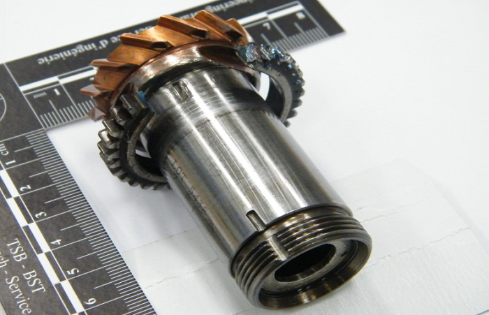
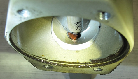
Removal of the reduction gear housing from the engine revealed that the intermediate spur gear (part number 896884-1) had failed and was no longer keyed to the torque sensor shaft (Photo 4). The intermediate spur gear transmits power, via the torque sensor shaft, from the high speed main shaft to a gear train which drives the high pressure fuel pump, fuel control unit, and oil pressure and scavenge pumps.
The torque sensor had accumulated approximately 6470 hours since overhaul in 1997. The torque sensor assembly does not have a designated overhaul period and is normally overhauled with the engine. The torque sensor was removed and visually examined by the manufacturer under the supervision of TSB investigators. The TSB Laboratory conducted a detailed examination of the torque sensor, as well as gear fragments, metal shavings and chips recovered from the reduction gear housing. See TSB Laboratory report LP 055/2011 – Metallurgical Examination of Torque Sensor.
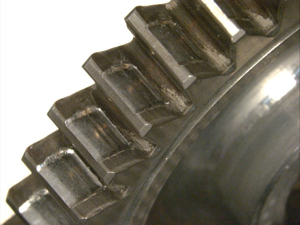
The laboratory analysis of the failed intermediate spur gear revealed fatigue cracks in the roots of most of the gear teeth. The gear had separated into several fragments as a result of fatigue cracking followed by overstress fractures. The woodruff key (part number MS35756-1) that indexed the gear to the torque sensor shaft had fractured in a fatigue mode followed by overstress fracture. The case hardening of the intermediate spur gear and one other spur gear (part number 3103589-1) in the gear train was slightly below the specified level on the tooth flanks and significantly lower in the tooth root areas. Both gears exhibited significant wear on the loaded faces and flanks of the gear teeth (Photo 5 and Photo 6).
The overhaul manual for the torque sensor states that "dimensional, magnetic particle, or fluorescent penetrant inspection procedures are required only when a visual inspection indicates wear or damage that is detrimental to the function of the parts."Footnote 15 A review of records provided by the overhaul agency indicated that the failed gear had not been subjected to magnetic particle or fluorescent penetrant inspection.
1.9.5 Left engine
The left engine (serial number P37046) had accumulated approximately 1805 hours since overhaul. Visual examination did not reveal any faults that would explain a power loss. Engine testing, using a test cell, was conducted by the manufacturer under TSB supervision. The engine performed normally as an assembly. The fuel control unit and fuel pump were then removed and tested individually with no faults detected. The solenoid fuel shutoff valve was removed and functionally tested with no faults detected. Subsequent disassembly of the valve revealed no defects.
1.9.6 Left wing fuel system examination
The left wing outboard of the engine nacelle was moved to the TSB regional wreckage examination facility in Winnipeg, Manitoba. The interior of the fuel tanks was examined and several discrepancies were identified.
The plastic tubing that delivered fuel from the No. 2 ejector pump was pinched and chafed at several points where the tubing passed through wing rib stringer cut-outs. The plastic tubing transitioned to an aluminum tube (part number 212-54227.3) at wing station 4300. Three aluminum tabs were welded to the tube to facilitate securing the assembly to the wing structure and the collector tank. Two of these tabs were broken, including the uppermost tab which was bolted to the forward face of the collector tank. The head of the bolt had chafed a small hole in the tube. The tube was also heavily chafed at the point where it entered the collector tank. The nature of these discrepancies indicate that they had developed over many hours of operation and predated the accident.
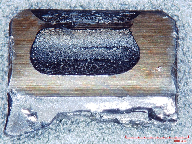
During the in-situ examination of the No. 2 ejector pump, a piece of flexible foreign object debris (FOD) fell out of the pump intake port. The piece of L-shaped FOD was approximately 2 mm thick, 4 mm wide and 13 mm long. Disassembly and examination of the No. 2 ejector pump nozzle revealed a stain approximately 4 mm wide (Photo 7).
Analysis of the FOD by the TSB Laboratory revealed that it was composed largely of a structure of polymeric materials. For comparison purposes, samples of sealant were removed from various locations in the fuel tank. Unlike the FOD, these samples were determined to be homogenous, particulate-filled polysulphide compounds.
1.9.7 Left wing fuel system testing
The testing protocol was developed during initial sessions in August and November 2011. The final round of testing was carried out in January 2012. The primary aim of the testing was to determine the ability of the fuel system to deliver fuel to the firewall in uncoordinated flight with various amounts of left bank.
A bank into the operating engine with uncompensated yaw results in uncoordinated flight. This will cause the fuel to move outboard in the low wing, away from the collector tank clack valves and the No. 1 ejector pump inlet. This fuel movement will be exacerbated because the bottoms of the fuel tanks are flat.
The testing also examined
- the effect of the chafed hole in the No. 2 ejector pump delivery pipe;
- the effect of the loose booster pump plumbing fittings;
- the ability of the No. 2 ejector pump to ingest the FOD into the pump nozzle;
- the effect of the FOD on the No. 2 ejector pump delivery rate;
- the functionality of the low fuel level and low fuel pressure warning switches and lights.
The wing was placed on a trestle to enable the wing to be tilted to various angles to simulate uncoordinated flight with 3°, 5°, and 7° of left bank. Royco 950 calibration fluid was used for the testing because of its low volatility and similar density to Jet A fuel.
The volume of usable fuel in the left wing at the time of the right engine power loss was determined to be approximately 356.5 litres. The volume of unusable fuel in the left wing was determined to be 33.5 litres by putting a known amount of fluid in the inboard fuel tank with the wing level and determining how much remained after pumping out as much fluid as possible with the booster pumps. The unusable volume of 33.5 litres was added to the 356.5 litres of usable fuel resulting in a total volume of 390 litres. This quantity of Royco 950 calibration fluid was then pumped into the wing.
The density of the Royco 950 calibration fluid used for testing was 1.68 pounds per litre. Therefore, 390 litres of Royco 950 weighed 655.2 pounds.
An empty drum on a digital scale was used to permit monitoring of the fluid flow rate throughout each test run, facilitate returning the fluid to the wing after each test run, and to keep the starting fluid level of each test run consistent. The ejector pump filter was replaced prior to commencing the testing.
Each test commenced with the wing level and the collector tank full. Fluid flow from the wing was controlled at a target rate of 456.6 pph (271.8 litres per hour) which is equivalent in volume to 500 pph of Jet A. The wing was then tilted to the applicable angle, the booster pump outlet flow was directed into the empty drum, and the timing commenced. The times at which the following events occurred were recorded:
- Exposure of No. 1 ejector pump inlet
- Illumination of low fuel level warning lamp and master caution lamp
- Audible booster pump cavitation
- Fuel pressure fluctuation reached 15 PSI
- Low fuel pressure warning lamp flicker
- Low fuel pressure warning lamp steady illumination and illumination of master caution lamp.
Tests were conducted with the wing in 4 conditions:
- No. 2 ejector pump unobstructed
- FOD manually positioned in the No. 2 ejector pump nozzle
- FOD ingested by the No. 2 ejector pump while in the wing
- FOD ingested by the No. 2 ejector pump while in the bench test rig.
When tested while installed in the wing, the No. 2 ejector pump (with the FOD removed) was found to flow a total of 415 pph to the collector tank. Of this, 116 pph was primary flow from the booster pump(s) needed to operate the ejector pump, resulting in a net fuel delivery to the collector tank of 299 pph. The primary fuel from the booster pump(s) to operate the No. 3 ejector pump was drawn from the collector tank and discharged into the inboard tank at a rate of approximately 138 pph. Consequently, when the No. 1 ejector pump inlet was not submersed, the resulting net flow to the collector tank was 161 pph (95.8 litres/hr) of Royco 950 equivalent in volume to 176 pph of Jet A.
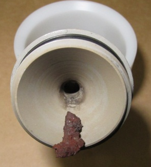
The No. 2 ejector pump (with the FOD removed) was removed from the wing and tested as described in the CASA C-212 Component Maintenance Manual 28-13-04 and was found to meet the specified delivery requirements. During the last series of bench tests, the FOD was positioned near the intake and was ingested into the pump. During the last ingestion test, the output flow decreased substantially as a result of the FOD lodging deep in the ejector nozzle (Photo 8). The pump was reinstalled in the wing in this condition (Appendix H) and 4 additional test runs were conducted.
All testing in January 2012 was performed with the leaks present at the booster pump check valves as found at the crash site. Earlier testing had shown that there was no significant decrease in the duration of fuel supply as a result of the loose fittings. Visual examination confirmed that the leaks were minor and that the fluid that leaked from the fittings tended to drip close to the No. 1 ejector pump inlet and was returned to the collector tank.
The chafed hole observed in the No. 2 ejector pump delivery pipe leaked fluid at a rate of 1.29 litres per hour. This leak rate over 14 minutes 5 seconds would not have had any material impact on engine operation.
During preparation for a test on 17 August 2011, the low level sensor did not operate during the filling of the collector tank. The low level warning lamp remained on for approximately 8 minutes, well after the collector tank was full. The top wing skin above the low level sensor was rapped sharply and the lamp extinguished.
From the series of tests (Appendix H), the following observations were made:
- A bank angle of 3° provided fluid flow to the engine of 500 pph for over 50 minutes.
- At a bank angle of 3°, the No. 1 ejector intake became exposed with 238 (204.5 usable) litres of fluid remaining in the wing.
- A bank angle of 5° provided fluid flow at 500 pph for approximately 33 minutes.
- A bank angle of 7° provided fluid flow at 500 pph for approximately 25 minutes.
- At a wing angle greater than 5.5°, the No. 1 ejector inlet became exposed with 390 (356.6 usable) litres of fluid remaining in the wing.
With the FOD in the No. 2 ejector pump, the following observations were made:
- When testing at a 5° wing angle, the No. 1 ejector pump inlet, even though exposed, continued to suck up some fluid that remained in the bay below the inlet until late into the test.
- When the wing was tilted to 5.8° no fuel remained in the bay below the No. 1 ejector pump inlet.
- A wing angle of 5° provided fluid flow to the engine of 500 pph for approximately 27 to 28 minutes, regardless of the FOD's location in the nozzle.
- A wing angle of 7° reduced fluid flow endurance at 500 pph to approximately 13 to 25 minutes, depending on the location of the FOD in the ejector pump nozzle.
- In condition D, usable fluid remaining in the wing after depletion of the collector tank varied from 233 litres (runs 18 and 20) to 286 litres (run 17).
Additional observations:
- The No. 1 ejector pump has sufficient delivery capacity to maintain the collector tank in an overflow condition while supplying 500 pph fuel flow to the engine.
- The No. 2 and No. 3 ejector pump system does not have sufficient capacity to prevent eventual depletion of the collector tank once the No. 1 ejector pump inlet becomes exposed.
- The primary flow from the No. 3 ejector pump does not return to the collector tank.
- During the occurrence flight, the low level warning likely illuminated approximately 3 to 4 minutes after the right engine lost power (about 10 minutes prior to collector tank depletion).
- During the testing, illumination of the low fuel pressure light and master caution annunciator was coincident with a substantial decrease in fluid flow.
1.9.8 Engine flameouts
The engine ignition system is in operation only during the starting sequence. Once started, combustion is continuous and self-sustaining as long as the engine is supplied with the proper fuel-to-air ratio.
Flameout is a term used to describe the condition in which combustion in a gas turbine engine unintentionally stops. This may be due to unusual attitudes, a malfunctioning fuel control system, blocked fuel supply, air introduction into the fuel delivery system, turbulence, icing, fuel starvation or fuel exhaustion.
The TPE-331-10R-511C engine, as installed on the CASA C-212, is not equipped with an auto ignition system, so if a flameout occurs, the engine will not automatically restart if the fuel to-air ratio is restored to normal operating parameters.
1.9.9 Annunciator panel
The 30-segment annunciator panel was mounted in the glare-shield below the front windscreen. The segments are arranged so as to group systems together, arranged in alternating columns for the left and right engines (Figure 2). Each annunciator panel segment contains 2 lamp bulbs. Both bulbs in the fuel level–left tank warning segment were found to be serviceable when examined in Saskatoon.
The annunciator panel incorporates a 2-position switch to alter the brightness of the panel between dim and bright to suit ambient conditions. The switch was damaged during the crash and it was not possible to determine the switch selection position or serviceability.
One lamp in each of the 4 following segments was unserviceable: right generator, right fuel level, and left SRL/start. Both lamps in the right fuel pressure segment were unserviceable.
The panel was sent to the TSB Laboratory for lamp filament analysis. When the bulbs from the fuel level left tank segment were examined, the filament in one lamp was found to be fractured. This likely occurred during transit. When the power is removed from a PN 327 lamp, it takes approximately 50 milliseconds to cool. Analysis of the crash revealed that the deceleration from 90 knots in 98 feet occurred in approximately 1.25 seconds. Since hot lamp filaments stretch, and the occurrence lamps had time to cool, it could not be confirmed that they were on at the time of impact. The main batteries and auxiliary battery were destroyed early in the crash sequence.
A master caution annunciator was located on each pilot's instrument panel below the glare-shield. Approximately 5 seconds after the illumination of a segment in the annunciator panel both master caution annunciators illuminate but do not flash. Either pilot may press the annunciator to acknowledge the warning and extinguish both master caution annunciators.
The annunciator panel, master caution annunciator system, interconnecting components and wiring were examined and no reason was identified for the display of any warnings to have been prevented.
1.10 Fire
There was no in-flight or post-crash fire.
1.11 Survival aspects
The survey equipment operator was found in the seat with the seatbelt still fastened and attached to the seat. The seat and operator were on the ground outside of the fuselage on the left side of the noise abatement wall. The seat legs had been fastened to a track in the floor on the right side of the cabin centre section. The structural integrity of this area of the aircraft was completely disrupted by the collision with the noise abatement wall, and the resulting forces were not survivable.
1.12 Tests and research
The following TSB Laboratory analysis was completed:
- LP 039/2011 – Fuel Analysis
- LP 042/2011 – Lamps & Fuel Data Analysis
- LP 055/2011 – Metallurgical Examination of Torque Sensor
- LP 151/2011 – Wire Examination
- LP 013/2012 – Metallurgical Analysis of FOD
The reports are available from the TSB upon request.
1.13 Organizational and management information
The flight was operating under Subpart 702 - Aerial Work of the Canadian Aviation Regulations.
1.14 Additional information
Police and firefighters arrived at the crash site within 2 minutes, followed shortly afterward by paramedics in ambulances, who transported the survivors to hospital for medical attention. The flight crew and first responders reported an odour of fuel present on the left side of the aircraft. There was no post-impact fire.
1.15 Useful or effective investigation techniques
Not applicable for this occurrence.
2.0 Analysis
Weather at the time of the occurrence and air traffic control involvement were not factors in the occurrence. The analysis will examine the reasons for the engine power losses and the crew responses to them.
2.1 Right engine power loss
TSB Laboratory analysis indicated that the case hardening of the gear tooth flanks and roots of 2 spur gears in the torque sensor gear train was below the manufacturer's specification requirements and likely led to the wear of the loaded faces and flanks of the gear teeth. The combined wear of the 2 gears likely caused an abnormal vibration that produced excessive cyclic loading and eventual fatigue cracking in the tooth roots of the intermediate gear. The intermediate spur gear subsequently separated into several fragments and caused the loss of power transmission to the high-pressure engine-driven fuel pump. The immediate result would have been fuel starvation of the engine, flameout and the loss of power.
If no detrimental wear or damage had been observed when the torque sensor was overhauled, there would have been no requirement for non-destructive inspection. Since it is not known how fast the gear tooth wear or fatigue cracks propagated, it is not certain that routine application of non-destructive testing during the 1997 overhaul would have revealed any defects.
In January 2009 a failed air start attempt was experienced at an outside air temperature of approximately −20 °C. Because it could not be determined whether the engine oil had cooled below the 4° C minimum temperature allowed prior to the restart attempt, and the engine had since operated 840 hours without further incident, the investigation could not determine what impact, if any, this event had on the failure mode of the intermediate spur gear.
The shudder felt was almost certainly associated with the gear failure. The engine-driven fuel pump was no longer operating so any attempt to restart the engine would have been unsuccessful.
When the right engine chip plug was removed it did not initially display electrical continuity so the chip warning light did not illuminate. The metal chips observed on the plug likely fell onto the plug during the recovery of the aircraft wreckage.
2.2 One engine inoperative performance
The investigation determined that the aircraft was flown with at least an average 5° left bank after the first engine power loss. However, the bank angle would have been greater than 5° as the flight made several left turns toward Saskatoon, and was less than 5° during some shallow right turns to position the aircraft on final approach. The variability of the bank angles was not considered to have significantly affected the aircraft's performance. However, variable left bank angles with left yaw could produce lateral accelerations that tend to move the fuel outboard in the left wing fuel tank.
Aircraft climb performance was marginal following the right engine loss of power. Factors which likely impaired climb performance are as follows:
- Both birds were deployed at the time and remained deployed for 3 to 4 minutes after the right engine power loss.
- Loss of thrust from the right engine combined with drag from the deployed birds resulted in the airspeed deteriorating below V2 (99 KIAS).
- After the initial deceleration, the aircraft slowly accelerated.
2.3 Bird recovery
For about 3 minutes after the right engine lost power, the aircraft operated in a high drag configuration with both birds deployed. The reason for this was that the pilots were initially uncertain whether the aircraft would maintain altitude, and recovering or jettisoning the birds required the survey equipment operator to leave his seat to do so. This resulted in reduced climb performance with one engine inoperative. Because the terrain was flat, this did not pose a hazard. Over terrain with more vertical relief, the reduced climb performance could present a controlled flight into terrain hazard.
2.4 Fuel system
Because the bottom of the wing has no dihedral, the fuel system depends on the ejector pumps to move fuel from outboard to inboard and into the collector tank. This dependence is increased in uncoordinated flight, such as single-engine flight after an engine power loss.
The usable fuel level in the left wing at the time of the right engine failure was approximately 656 pounds. At that fuel level, the No. 1 ejector pump inlet would have been exposed if the bank angle in uncoordinated flight exceeded 5.8 degrees. In this condition, the No. 2 ejector pump would have been the only means of fuel transfer to the collector tank.
Without foreign object debris (FOD) present, the depletion rate of the collector tank was approximately 324 pph. This is the difference between the engine fuel consumption of 500 pph at full power and the net fuel transfer rate of 176 pph to the collector tank from the No. 2 and No. 3 ejector pumps. With no input from the ejector pumps, the collector tank should have been able to supply fuel for almost 19 minutes.
With the FOD present, and depending on the position of the FOD in the No. 2 ejector pump nozzle, testing demonstrated that the ability of the collector tank to supply fuel was approximately 13:21 to 16:03 minutes. The length of time between the right engine power loss and the left engine power loss was 14:05 minutes.
During normal coordinated flight the No. 1 ejector pump, because of its larger capacity, can maintain the collector tank in an overflow condition; consequently, there would be no indication to the crew that the performance of the No. 2 ejector pump had been compromised.
Analysis of the FOD material revealed that it was dissimilar to the type of sealant material utilized in the construction, repair or maintenance of the fuel tank, but it could not be determined how or when the FOD was introduced into the fuel tank. The staining of the No. 2 ejector pump nozzle indicates that it had been present for some time prior to the accident flight. The origin of the materials in the FOD was not determined. The inlets of the ejector pumps are unscreened; consequently, FOD of a compatible size and shape present in the fuel tank could be ingested into the nozzle area of the ejector pump.
The booster pump check valve fittings were not completely tight and there was a small hole chafed in the No. 2 ejector pump delivery pipe. These defects did not appreciably diminish the ability of the collector tank to supply fuel to the engine. However, if the engine had been running with the boost pumps inoperative, the loose check valve fittings would have allowed air to be drawn into the fuel system. The pinching of the No. 2 ejector pump plastic delivery tube at the wing stringer cut-outs did not affect the fuel delivery rate, but if the associated chafing had resulted in the tubing being pierced, fuel transfer would have been limited. Finally, the cracking of the welded tabs on the No. 2 ejector pump delivery pipe and subsequent chafing where the pipe entered the collector tank would have limited the transfer of fuel if it had been allowed to progress.
2.5 Low fuel level warning
During TSB testing of the fuel system, the low level float sensor operated correctly and illuminated the "fuel level–left tank" annunciator every time fluid was being pumped out of the collector tank. The sensor failed to operate on only one occasion, and this occurred while the collector tank was being filled. The tests were conducted with the wing stationary in a test jig. In flight, the system would have been subjected to engine, propeller, and airframe vibration which would tend to prevent the float sensor from sticking in position.
It is possible that the float stuck during the occurrence flight as the collector tank became depleted and prevented the illumination of the low level warning lamp. However, this is considered to be unlikely. On balance, it is likely that the low fuel level warning system was functioning normally during the occurrence flight.
The left low fuel level warning lamp and the master caution lamp likely illuminated approximately 3 to 4 minutes after the right engine power loss.
There are several reasons why the warning was not perceived by the crew:
- The systems-oriented arrangement of the annunciator panel placed the "fuel level left tank" segment adjacent to segments that were already illuminated as a result of the right engine power loss and shutdown (Figure 3). Consequently, the illumination of a new warning light adjacent to those already indicating status of the shut-down engine is less likely to be perceived or associated with the operating engine.
- There may have been no master caution warning associated with the low fuel level if it occurred before the crew acknowledged and cancelled the master caution warning triggered by the right engine power loss.
- The increasing intensity of sunlight through the cockpit windows as the aircraft turned to the west may have made the warning hard to see.
- The crew was also communicating with Saskatoon air traffic control and attempting to visually locate the runway several nautical miles ahead.
- The left low fuel level warning lamp likely illuminated approximately 3 to 4 minutes after the right engine power loss, at a time of relatively high cockpit workload.
- The master caution annunciator may not have captured the crew's attention due to the absence of a flashing function.
The pilots did not execute the fuel level warning checklist because they did not perceive the illumination of the fuel level left tank warning light. Consequently, the fuel crossfeed valve remained closed and fuel from only the left wing was being supplied to the left engine.
2.6 Left engine power loss
The left fuel pressure was normal following completion of the engine failure in flight procedure for the right engine power loss. Therefore, the crew did not inadvertently turn off the left boost pumps during the right engine power loss procedure. When the before-landing checklist was performed, the right booster pumps were turned back on. At this time there would have been 2 green lights illuminated on the overhead booster pump control panel indicating that both auxiliary pumps were selected "on". Until the captain reached up for the emergency handle after the loss of power had occurred, his hands were nowhere near the overhead panel. Therefore, he could not have inadvertently closed the fuel valve on the left engine.
The left engine power loss was likely caused by fuel starvation resulting from operating at various bank angles and left yaw with a compromised fuel system. This flight attitude exposed the No. 1 ejector pump, and the reduced output of the contaminated No. 2 ejector pump led to the depletion of the collector tank.
As the booster pump output pressure and flow decreased, the engine became fuel starved and experienced a loss of power likely followed by a flameout. Testing of the fuel system demonstrated that the illumination of the low fuel pressure warning light was probably coincident with the left engine power loss.
2.7 Flight following
The SkyTrac system provided timely position information and would likely have assisted search and rescue personnel if position data had been required. The ELT was damaged and did not activate or transmit. Neither system was required because the flight was on air traffic control radar and its position was known.
2.8 Annunciator bulb analysis
Lamp filament analysis performed by the TSB Laboratory indicated that no annunciator lamps could be confirmed to have been illuminated at the time of impact. However, the main batteries and auxiliary battery were destroyed early in the crash sequence. Because of the cooling rate of the lamp filaments and the aircraft's deceleration time, it is likely that the lamps had time to cool so the lamp filaments did not distort sufficiently to be confirmed "on" by laboratory analysis.
2.9 Forced landing
When the left engine lost power, the aircraft was approximately 3.4 nm from the threshold of runway 27. The crew immediately determined that it was not possible to extend the glide to the airport.
The crew had limited altitude and time to prepare for and execute the forced landing. Although the multiple engine failure procedure specified the flaps should be retracted, the crew elected to leave them at the current setting of 25%. Had the flaps been retracted, they would have needed to be re-extended a short time later to prepare for the forced landing, and any improvement in glide performance resulting from flap retraction would not have been sufficient for the aircraft to reach the runway or a better landing site than the one chosen.
The site that was chosen for the forced landing offered the most likelihood of success with the least risk to persons on the ground. The crew landed the aircraft under control while avoiding a busy highway to the left and residential buildings on the right. The concrete noise abatement wall ran parallel to the roadway and initially would have been difficult to see from the air. The crew received immediate assistance from bystanders and were aided by a quick response from Saskatoon emergency services personnel.
2.10 Flight recorders
The aircraft was not required to be equipped with certified flight recorders. When cockpit voice and flight data recordings are not available to an investigation, this may preclude the identification and communication of safety deficiencies to advance transportation safety.
3.0 Conclusions
3.1 Findings as to causes and contributing factors
- The right engine lost power when the intermediate spur gear on the torque sensor shaft failed. This resulted in loss of drive to the high-pressure engine-driven pump, fuel starvation, and immediate engine stoppage.
- The ability of the left-hand No. 2 ejector pump to deliver fuel to the collector tank was compromised by foreign object debris (FOD) in the ejector pump nozzle.
- When the fuel level in the left collector tank decreased, the left fuel level warning light likely illuminated but was not noticed by the crew.
- The pilots did not execute the fuel level warning checklist because they did not perceive the illumination of the fuel level left tank warning light. Consequently, the fuel crossfeed valve remained closed and fuel from only the left wing was being supplied to the left engine.
- The left engine flamed out as a result of depletion of the collector tank and fuel starvation, and the crew had to make a forced landing resulting in an impact with a concrete noise abatement wall.
3.2 Findings as to risk
- Depending on the combination of fuel level and bank angle in single-engine uncoordinated flight, the ejector pump system may not have the delivery capacity, when the No. 1 ejector inlet is exposed, to prevent eventual depletion of the collector tank when the engine is operated at full power. Depletion of the collector tank will result in engine power loss.
- The master caution annunciator does not flash; this leads to a risk that the the crew may not notice the illumination of an annunciator panel segment, in turn increasing the risk of them not taking action to correct the condition which activated the master caution.
- When cockpit voice and flight data recordings are not available to an investigation, this may preclude the identification and communication of safety deficiencies to advance transportation safety.
- Because the inlets of the ejector pumps are unscreened, there is a risk that FOD in the fuel tank may become lodged in an ejector nozzle and result in a decrease in the fuel delivery rate to the collector tank.
3.3 Other findings
- The crew's decision not to recover or jettison the birds immediately resulted in operation for an extended period with minimal climb performance.
- The composition and origin of the FOD, as well as how or when it had been introduced into the fuel tank, could not be determined.
- The SkyTrac system provided timely position information that would have assisted search and rescue personnel if position data had been required.
- Saskatoon police, firefighters, and paramedics responded rapidly to the accident and provided effective assistance to the survivors.
4.0 Safety action
4.1 Action taken
4.1.1 Fugro Aviation Canada Limited
Fugro grounded its remaining CASA C-212 aircraft immediately following the occurrence. Before recommencing operations on 30 June 2011, the company
- revised its CASA C-212 one engine inoperative emergency procedures to include supplying the operating engine with fuel from both the left and right tanks by opening the crossfeed valve; and
- modified the aircraft with a remote-controlled cable cutter on the bird tow cables. This cutter permits the pilots to jettison the birds from the cockpit, eliminating the requirement for the survey equipment operator to leave his seat, and allows the pilots to quickly improve the climb performance of the aircraft in the event of a loss of engine power.
In October 2011, the aircraft was modified with the installation of a continuous ignition system for the engines.
Fugro has also increased the frequency and expanded the scope of some maintenance inspections of the CASA C-212 fuel system, including cleaning of the ejector pump nozzles.
4.1.2 Transport canada
On 14 April 2011, Transport Canada conducted an inspection of Fugro's operational control and maintenance release processes exercised for the occurrence flight. The process inspection was conducted in accordance with Civil Aviation Staff Instruction SI-SUR-001, Issue 4. The inspection determined all processes reviewed met applicable regulatory requirements and were being followed as described in approved company manuals.
4.1.3 Honeywell aerospace
Honeywell Aerospace has initiated a revision to the component maintenance manual for the torque sensor. The revision will require a magnetic particle inspection of the spur gear in addition to visual inspection.
4.1.4 Airbus military
Airbus Military has initiated a revision to the CASA C-212 Airplane Flight Manual procedure for engine failure in flight. The revision adds a caution that the following steps must not be actioned if a fuel leak on the affected side exists, and adds 2 subsequent procedural steps to turn the normal fuel booster pump for the failed engine "on" and to move the fuel feeding lever to the "crossfeed" position.
This report concludes the Transportation Safety Board's investigation into this occurrence. Consequently, the Board authorized the release of this report on . It was released on .
5.0 Appendices
Appendix A - Flight path 1814 to 1825:36
Appendix B – Engine failure in flight procedure
Appendix C – Flight path 1825:36 to 1830:02
Appendix D – Before landing check
Appendix E – Multiple engine failure and emergency landing procedures
Appendix F – Fuel level warning procedure
Appendix G – Fuel pressure warning procedure
Appendix H – Left wing fuel system testing results
Table H1. Condition A: Number 2 pump clean
| Test run number | Date of test run | Recorded fuel pressure | Recorded primary pressure | Flow rate (pounds per minutes) | Wing angle (degrees) | Exposure of #1 ejector | Illumination of low-level warning indicator | Audible pump cavitation | Pressure fluctuation | Flickering of low-pressure lamp | Illumination of low-pressure caution lamp |
|---|---|---|---|---|---|---|---|---|---|---|---|
| Pounds per square inch | Time of onset from beginning of test (minutes:seconds) | ||||||||||
| 1 | 3-Jan-12 | 21 | 14 | 15.4/2:00 | 3 | 33:24 | 37:14 | n/a | n/a | n/a | n/a |
| 2 | 3-Jan-12 | 21 | 14 | 84.2/not recorded | 5 | 9:11 | 13:25 | 30:49 | 30:54 | n/a | 31:11 |
| 3 | 4-Jan-12 | 21 | 14 | 30.4/4:00 | 6.8 | 1:02 | 5:17 | 22:34 | 22:56 | n/a | 23:12 |
| 11 | 4-Jan-12 | 21 | 14 | 143.6/19:00 | 7 | 00:56 | 5:46 | 24:02 | 24:49 | 25:06 | 25:19 |
| 12 | 4-Jan-12 | 21 | 14 | 76.6/10:00 | 7 | 00:55 | 5:42 | 23:39 | 24:29 | 24:45 | 24:59 |
| 13 | 5-Jan-12 | 21 | 14 | 77.4/10:00 | 5 | 9:29 | 13:58 | 32:05 | 32:42 | 32:58 | 33:12 |
| 14 | 5-Jan-12 | 21 | 14 | 100/13:00 | 5 | 9:30 | 14:04 | 32:20 | 32:43 | 33:01 | 33:17 |
Table H2. Condition B: Number 2 pump with foreign object debris positioned manually
| Test run number | Date of test run | Recorded fuel pressure | Recorded primary pressure | Flow rate (pounds per minutes) | Wing angle (degrees) | Exposure of #1 ejector | Illumination of low-level warning indicator | Audible pump cavitation | Pressure fluctuation | Flickering of low-pressure lamp | Illumination of low-pressure caution lamp |
|---|---|---|---|---|---|---|---|---|---|---|---|
| Pounds per square inch | Time of onset from beginning of test (minutes:seconds) | ||||||||||
| 4 | 4-Jan-12 | 21 | 15 | 23.4/3:00 | 3 | 29:40 | 36:23 | 49:35 | 49:40 | n/a | 50:31 |
| 5 | 4-Jan-12 | 21 | 15 | 152.4/20:00 | 5 | 8:05 | 12:16 | 25:25 | 25:33 | 25:48 | 27:45 |
| 6 | 4-Jan-12 | 21 | 15 | 61/8:00 | 7 | 0:58 | 3:20 | 12:36 | 12:59 | 13:09 | 13:21 |
| 7 | 4-Jan-12 | 21 | 15 | 38.2/5:00 | 5 | 8:21 | 12:46 | 25:36 | 26:01 | 26:19 | 28:22 |
| 8 | 4-Jan-12 | 21.5 | 15 | 75.8/10:00 | 5 | 8:21 | 12:41 | 25:12 | 25:47 | 26:06 | 27:54 |
| 9 | 4-Jan-12 | 21 | 15 | 74.2/10:00 | 7 | 0:58 | 3:21 | 12:33 | 13:01 | 13:09 | 13:23 |
| 10 | 4-Jan-12 | 21 | 15 | 61.2/8:00 | 7 | 0:58 | 3:26 | 12:42 | 13:20 | 13:29 | 13:34 |
Table H3. Condition C: Number 2 pump with foreign object debris ingested in wing
| Test run number | Date of test run | Recorded fuel pressure | Recorded primary pressure | Flow rate (pounds per minutes) | Wing angle (degrees) | Exposure of #1 ejector | Illumination of low-level warning indicator | Audible pump cavitation | Pressure fluctuation | Flickering of low-pressure lamp | Illumination of low-pressure caution lamp |
|---|---|---|---|---|---|---|---|---|---|---|---|
| Pounds per square inch | Time of onset from beginning of test (minutes:seconds) | ||||||||||
| 15 | 5-Jan-12 | 21 | 14 | 30.4/4:00 | 7 | 0:53 | 5:34 | 23:21 | 24:15 | 24:30 | 24:46 |
| 16 | 5-Jan-12 | 21 | 14 | 14.8/2:00 | 7 | 0:59 | 5:43 | 23:39 | 24:29 | 24:45 | 24:59 |
Table H4. Condition D: Number 2 pump with foreign object debris ingested during bench test
| Test run number | Date of test run | Recorded fuel pressure | Recorded primary pressure | Flow rate (pounds per minutes) | Wing angle (degrees) | Exposure of #1 ejector | Illumination of low-level warning indicator | Audible pump cavitation | Pressure fluctuation | Flickering of low-pressure lamp | Illumination of low-pressure caution lamp |
|---|---|---|---|---|---|---|---|---|---|---|---|
| Pounds per square inch | Time of onset from beginning of test (minutes:seconds) | ||||||||||
| 17 | 6-Jan-12 | 21 | 14 | 30/4:00 | 7 | 0:56 | 3:47 | 14:31 | 15:12 | 15:25 | 15:38 |
| 18 | 6-Jan-12 | 21 | 14 | 30.2/4:00 | 5 | 8:47 | 12:43 | 25:18 | 25:59 | 26:21 | 27:12 |
| 19 | 6-Jan-12 | 21 | 14 | 14.5/2:00 | 7 | 0:53 | 3:54 | 14:54 | 15:39 | 15:52 | 16:03 |
| 20 | 6-Jan-12 | 21 | 14 | 45.4/6:00 | 5 | 8:47 | 12:46 | 25:24 | 26:06 | 26:26 | 27:12 |
