Collision with terrain
Airspan Helicopters Ltd.
Eurocopter AS350 B2 (helicopter)
C-GJPW
Key Lake, Saskatchewan, 11 nm SE
The Transportation Safety Board of Canada (TSB) investigated this occurrence for the purpose of advancing transportation safety. It is not the function of the Board to assign fault or determine civil or criminal liability. This report is not created for use in the context of legal, disciplinary or other proceedings. See Ownership and use of content. Masculine pronouns and position titles may be used to signify all genders to comply with the Canadian Transportation Accident Investigation and Safety Board Act (S.C. 1989, c. 3).
Summary
The Airspan Helicopters Ltd. Eurocopter AS350 B2 (registration C-GJPW, serial number 4738), was conducting aerial work approximately 11 nautical miles southeast of Key Lake Airport, Saskatchewan. At approximately 1231 Central Standard Time, the helicopter began an uncommanded roll and rotation to the left, descended, and collided with the terrain. The pilot, who was the sole occupant, sustained serious injuries but was able to evacuate without assistance. The 406 MHz emergency locator transmitter activated on impact, and the signal was detected by the search-and-rescue satellite system. The helicopter sustained substantial damage. There was no post-impact fire.
Factual information
History of the flight
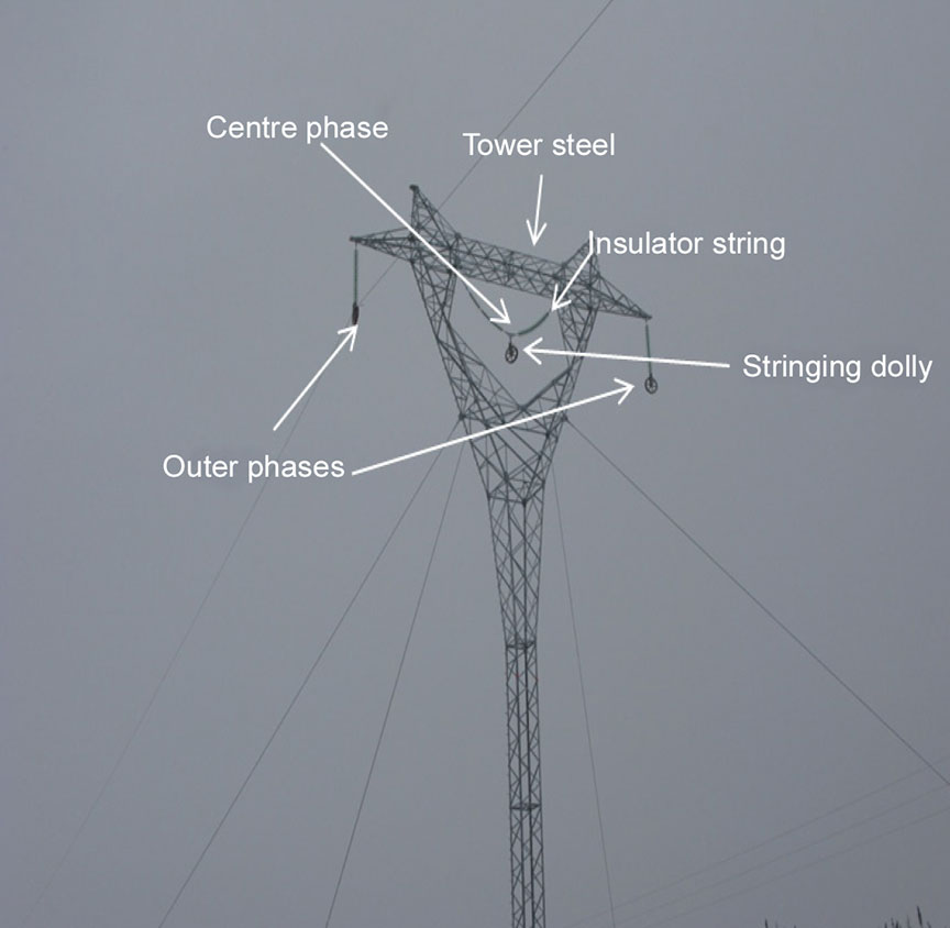
On the day of the occurrence (21 January 2015) at approximately 0700,Footnote 1 the pilot attended a ValardFootnote 2 company meeting. The meeting participants discussed the plan for the day, which consisted of using a helicopter to string steel feeder cable through a row of 14 steel hydro towers spanning a distance of approximately 2.7 nautical miles (nm). The towers, which reach a height of approximately 125 feet above ground level (agl), each consist of a tower steel, 2 outer phases, and 1 centre phase (Figure 1). A tool called a “needle” is used to guide the feeder cable through the centre phase below the insulator string (Appendix A). The procedure for threading the centre phase was not discussed during the company meeting, nor was the procedure reviewed with the pilot before stringing operations commenced that day, contrary to Valard company procedures.
Before the day's flights on the Eurocopter AS350 B2 (registration C-GJPW, serial number 4738), the pilot did not perform a test of the electrical release button or of the mechanical release handle of the cargo hook, as required by the Onboard Systems Rotorcraft Flight Manual Supplement (RFMS) and the Eurocopter Cargo Sling RFMS. At approximately 0915, the pilot, who was seated in the right-hand seat, flew the helicopter from the base camp to the puller site, approximately 16 nm away. The puller site consists of 3 large spools of feeder cable. The large spools are anchored to the ground, and each spool is equipped with a manual hand-brake system. The feeder cable is 0.5-inch Tesmec braided cable manufactured of high-strength steel. Once at the site, the pilot proceeded to string the outer phase on the east side of the 14 towers. The pilot had flown other types of helicopters in which the electrical hook release button was located in different positions on the cyclic control stick and was therefore concerned about pushing the wrong button. Consequently, the pilot intended to use the mechanical release in case of an emergency, to prevent inadvertent release of the external load. After stringing the outer phase on the east side of the towers, the pilot returned to the base camp to refuel the helicopter before continuing stringing operations.
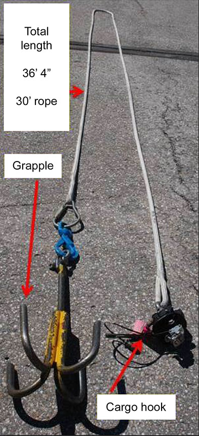
At approximately 1050, the pilot began stringing the centre phase of the towers using the needle and a grapple (Appendix B). It could not be determined whether the electrical release system was armed before the flight. The grapple, which is attached to the helicopter's cargo hook by approximately 36 feet of grapple line, is a tool used to lift, manoeuvre, and pull the needle through the centre of the tower. This process is known as “threading the needle.” The pilot completed the first 10 centre phases without incident.
Global positioning system (GPS) data showed that the helicopter was operating at an altitude of approximately 140 feet agl and at a ground speed of 8 knots while threading the needle through the 11th tower. While threading this tower, the helicopter was moving sideward on a northerly track, yawed approximately 90° to the right (facing east), which placed the grapple line assembly at approximately the helicopter's 3 o'clock position. The company procedures did not specify an ideal pulling position when threading the needle. As the helicopter lifted the needle off the front of the tower steel, below the insulator string, and started to pull the needle under the insulator string, the needle suddenly lunged momentarily in the direction the helicopter was pulling, and then abruptly stopped. The helicopter began an uncommanded rapid left roll, yawed to the left, descended, and collided with terrain.
During the descent, the pilot released the grapple line using the mechanical release handle. The pilot subsequently attempted to arrest the descent by applying full collective control. The time from the moment that the helicopter began to roll until the point of impact was approximately 3–5 seconds.
Company information
Airspan Helicopters Ltd. (Airspan) operates under Subparts 702 and 703 of the Canadian Aviation Regulations (CARs),Footnote 3 providing aerial work and air charter services. Airspan had been contracted by Valard, a utility contractor, to lift the steel cable into position on the hydro towers using a helicopter (“stringing operations”). Airspan did not have a fully implemented safety management system in place, nor was one mandated by Transport Canada (TC).
Personnel information
The pilot held a commercial helicopter licence restricted to daylight flying only. This was the first time that the pilot had conducted this type of external load operations. Records indicate that the pilot was certified and qualified for the flight in accordance with existing regulations.
| Total flying hours | 2700 |
|---|---|
| Hours on type | 570 |
| Hours in the last 7 days | 3.7 |
| Hours in the last 30 days | 3.7 |
| Hours in the last 90 days | 51.6 |
The pilot had been on duty for 5.5 hours at the time of the accident and had received a minimum of 10 hours off duty before the work period. The day of the occurrence was the pilot's third workday after 39 days off. The investigation did not indicate that the pilot's performance was affected by fatigue.
Training
The behaviour of any skilled operator, including pilots, can be classified according to 3 broad categories: skill-based, rule-based, and knowledge-based.Footnote 4 Skill-based behaviour occurs when an operator uses stored routines—or motor programs—that have been learned with practice and can be executed without conscious thought. Rule-based behaviour, on the other hand, is based on an operator fulfilling a set of rules, which can be stored in a pilot's long-term memory, or referred to, for example, in a checklist. Knowledge-based behaviour is that for which no procedure has been established. The progression of a pilot from novice to expert in a given task evolves from primarily rule-based (generally slow, capacity-limited, and effortful) behaviour to skill-based (fast, high-capacity, and relatively effortless) behaviour through adequate and effective training, practice, and feedback.
The pilot was hired by Airspan in May 2014. Since the pilot already held a valid pilot proficiency check on the AS350 helicopter, only company transition training was provided. This training consisted of company-related ground training requirements and 1 flight with a training pilot. The pilot received a total of 8.9 flight hours of documented training, including wire-environment flight training, of which 6.0 flight hours were in the occurrence aircraft. None of the documented flight training included stringing operations.
In September 2014, the occurrence pilot was trained by 2 company pilots in conducting stringing operations, as the pilot had never done this type of work before. The training, which was not documented, consisted of ground briefings and approximately 5–8 flight hours observing from the back seat while the training pilot completed the stringing operations. The occurrence pilot never took control of the helicopter during the training. This approach is not considered best practice as an instructional technique. According to Human Factors in the Training of Pilots,Footnote 5 “the student should be given the opportunity to actually perform and not spend hours watching the instructor perform.” TC's Helicopter Flight Instructor GuideFootnote 6 highlights, moreover, that “no one ever learns except through their own activity.” In addition, the company did not complete a competency check on the occurrence pilot to verify his proficiency in stringing operations.
On 20 January 2015, the occurrence pilot was briefed by another company pilot, who was conducting stringing operations that day. As the occurrence pilot had not yet completed any practical stringing operations and his stringing operations training had been completed in September 2014, the 1.5-hour briefing consisted of information on the process for stringing operations and details about the job site.
Aircraft information
The Eurocopter (now Airbus Helicopters) AS350 B2 was a single-engine (Turbomeca Arriel 1D1, serial number 19333) helicopter equipped with a semi-rigid main rotor and a flexible see-saw tail rotor. The helicopter had high-skid landing gear and was configured to carry a pilot and up to 5 passengers. The helicopter was certified with a maximum take-off weight of 4961 pounds, for day and night flights under visual flight rules. A review of the technical records indicates that the helicopter had accumulated a total of 2253 flight hours and that there were no deferred or outstanding defects. The investigation determined that, on the day of the occurrence, there were no technical issues with the helicopter.
Weight and balance
The pilot did not complete a weight-and-balance calculation before the flight. A review of the empty and operational weight and balance, conducted by TSB investigators, revealed that the helicopter was within the specified limitations at take-off for the occurrence flight. At the time of the occurrence, the helicopter had approximately 450 pounds of fuel on board.
The occurrence helicopter was equipped with a platform on its right side, for deploying workers onto towers, and a cargo basket on its left side. The cargo basket contained 100 pounds of ballast, and there was another 100 pounds of ballast in the left baggage compartment. The ballast weights were not required for the occurrence flight. Additional ballast would be required only if external personnel were being transported on the platform.
Helicopter external loads
Helicopters are used for a variety of aerial work, including external load operations. External load operations are categorized into 4 groups, depending on the work performed and the design limitations of the helicopter. TC defines external loads as follows:
Helicopter Class A external load means an external load that cannot move freely, cannot be jettisoned and does not extend below the landing gear;
Helicopter Class B external load means an external load that can be jettisoned and that is not in contact with land, water or any other surface;
Helicopter Class C external load means an external load that can be jettisoned and that remains in contact with land, water or any other surface;
Helicopter Class D external load means an external load with a person carried externally or any external load, other than a Class A, B or C external load.Footnote 7
Helicopter external load certification
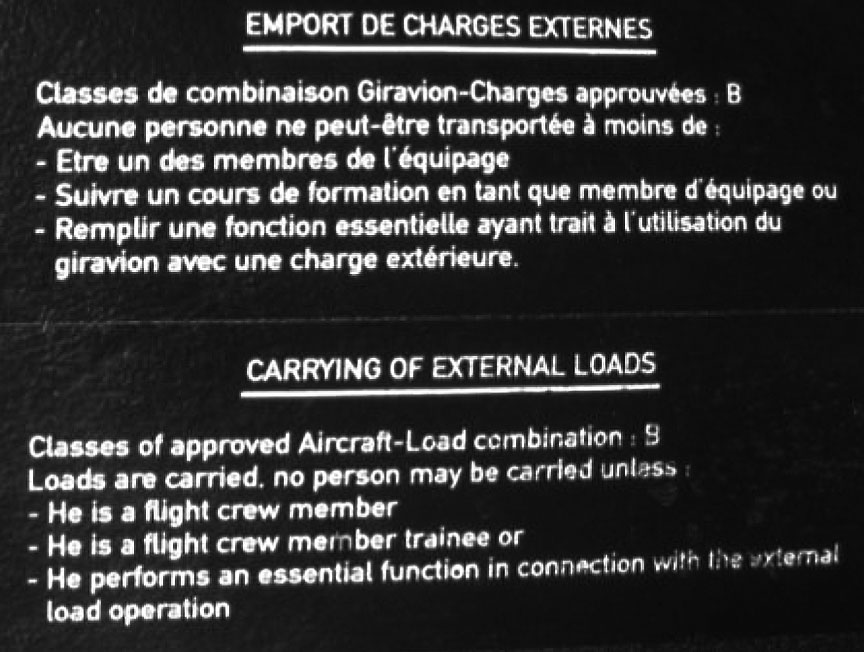
The AS350-series helicopter is approved for Class B external load operations in accordance with the Eurocopter Flight Manual AS350 B2 Supplement.Footnote 8 A placard was installed in the cockpit to identify the class of approved load combination as Class B (Photo 1).
On 11 December 2014, the helicopter was modified to add an external load cargo hook under the authority of a Supplemental Type Certificate (STC) no. SR01165SE. The cargo hook is attached directly to the belly of the helicopter at a single point and allows the helicopter to carry out Class B external load operations with a maximum authorized sling load of up to 1660 pounds.
The cargo hook is certified with 2 release systems: 1 electrical and 1 mechanical. The electrical release system must be armed by the pilot and is actuated by a push button on the cyclic control stick. The mechanical release is activated by squeezing a mechanical lever mounted on the collective pitch control lever.
The Rotorcraft Flight Manual Supplement supplied by the STC owner of the cargo hook states, “This cargo hook is approved for non-human cargo, class B and C rotorcraft load combinations only.”Footnote 9 The owner of the STC confirmed that the cargo hook limitation applies only to the hook and does not override the aircraft external load limitation specified in the flight manual.
Meteorological conditions
At 1200, the aerodrome routine meteorological report for the Key Lake Airport (CYKJ), Saskatchewan, located approximately 11 nm to the northwest of the occurrence, indicated wind 190° true at 7 knots, visibility 9 statute miles, an overcast layer based at 7000 feet agl, temperature −10 °C, dew point −10 °C, and altimeter setting 29.90 inches of mercury. The prevailing weather was not considered to be a contributing factor in the occurrence.
Stringing operations
Since the stringing operations involved feeder cable supplied from a drum secured to the ground, they were classified as a Class C helicopter external load operations. The puller site was located at the far end of the row of towers being strung. An individual, referred to as the brakeman, uses the handbrake on each drum to control the tension of the cable, as instructed by the helicopter pilot. The cable pull tension is monitored by the pilot from the cockpit using a display called a load meter. A load cell is mounted on the cargo hook and indicates the amount of force in pounds being applied to the hook. Radio communication among the brakeman, the ground crew, and the pilot was maintained throughout stringing operations. Valard ground personnel were stationed at selected towers to observe feeder cable pull and tension. On the day of the occurrence, the ground crew did not report any problems with the feeder cable pull.
At the time of the accident, the closest observer was approximately 0.34 nm from the occurrence tower. This distance, together with the rolling terrain, made it difficult to see the feeder cable or the needle at the occurrence tower. The ground personnel were not equipped with binoculars. For safety reasons, Valard standard operating procedures require that workers remain off the towers and do not permit traffic under the feeder cable when stringing operations are in progress.
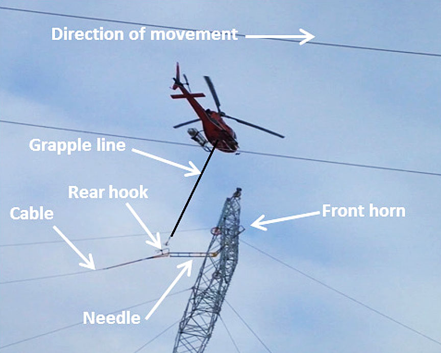
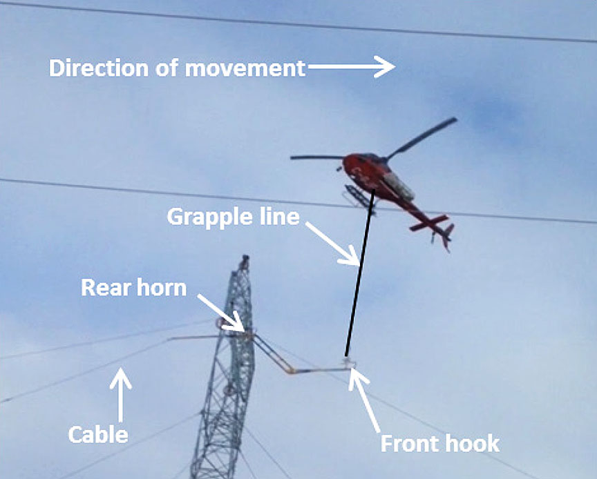
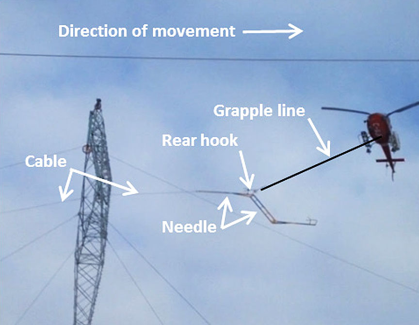
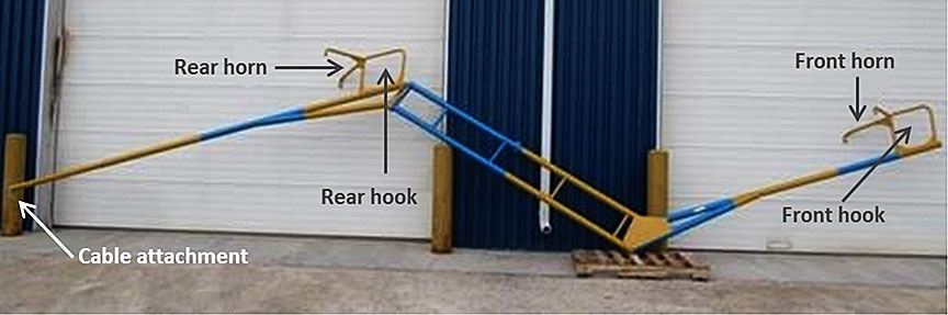
For centre-phase stringing operations, the feeder cable is attached to the rear of the needle. The helicopter is manoeuvred first to attach the grapple to the needle's rear hook and then to slowly guide the needle under the insulator string until the needle's front horn is caught on the tower steel (Figure 2).Footnote 10 Once the front horn is caught on the tower steel, the pilot manoeuvres the helicopter to remove the grapple from the needle's rear hook and repositions the helicopter to the opposite side of the tower. There, the helicopter is manoeuvred to attach the grapple to the needle's front hook. The pilot then lifts the front horn off the tower steel and pulls the needle partially under the insulator string until the rear horn is caught on the tower steel (Figure 3). Finally, the pilot hooks the grapple back onto the needle's rear hook to pull the feeder cable through the centre, drops the cable into the stringing dolly (Figure 1) and continues to the next tower (Figure 4).
Pulling the feeder cable requires higher engine power and a cyclic input in the direction of travel to overcome the weight of the needle and the feeder cable. The cyclic control tilts the main-rotor thrust vector, which controls the direction the helicopter moves. The feeder cable tension and the positioning of the helicopter during the feeder cable pull occasionally result in contact between the grapple line and the skid gear.
Wreckage and impact information
The terrain at the accident site was uneven and consisted of recently cut trees, deadwood, and large boulders (Figure 5). The helicopter landed on top of a large boulder in a level attitude with very little forward speed, and it did not leave a wreckage trail. Most of the impact forces were absorbed by the aft portion of the cabin, where the helicopter had made contact with the boulder, causing the cabin floor to collapse. The remainder of the cabin and the cockpit sections were suspended in the air. There was no deformation to the pilot seat.
After the collision, the helicopter remained in an upright position facing northeast. The left skid was in contact with the ground, whereas the right skid was found collapsed. The investigation determined that the engine was producing power at the time of the impact, and there were no signs of pre-impact anomalies.
The helicopter was equipped with a vehicle and engine monitoring display (VEMD), a multifunction screen that displays, in the flight mode, vehicle and engine parameters and, in a maintenance mode, parameters that have been exceeded, failure information, and a flight report. The VEMD recorded one short torque exceedance (3 seconds), which had reached a maximum value of 124%, consistent with an abrupt change in collective control during the accident sequence. The VEMD also recorded a 3-second engine free-turbine overspeed of 120.49%, which likely occurred subsequent to the loss of the coupling between the engine and the main gear box as a result of the ground impact.
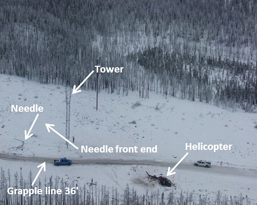
The needle and grapple line were found on the opposite side of the occurrence tower from the location where the helicopter had come to rest. The grapple line was no longer connected to the helicopter's cargo hook. The lead section of the needle was bent, and the horn was broken off. The feeder cable was still attached to the needle, and it was determined that the feeder cable was fully continuous to the cable drum.
A visual inspection of the feeder cable revealed tree bark embedded in the cable strands. The investigation determined that the Tesmec cable has a rough exterior and, given its weight and length, can make contact with the ground between towers and become snagged.
An inspection of the occurrence tower structure did not reveal any deformation around the area where the needle would contact the tower during stringing. An inspection of the previous tower found markings and paint transfer comparable to that on the occurrence tower.
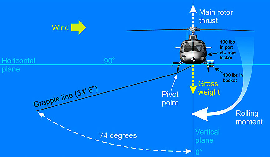
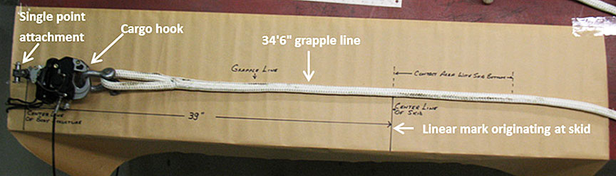
An inspection of the grapple line used during the occurrence flight revealed a linear mark originating at a distance that corresponded with the bottom of the landing gear skid (Figure 6). The mark suggested that contact had been made between the grapple line and the bottom of the landing gear skid and that the angle achieved to make contact with the skid was as high as 74°.
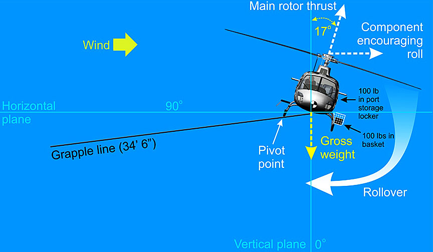
Dynamic rollover
One of the hazards associated with helicopter operations is dynamic rollover, which may occur during take-off, landing, or hovering, or while carrying an external load that is attached to the ground.Footnote 11, Footnote 12 Dynamic rollover occurs when angular momentum causes a helicopter to roll or pivot around a skid or landing gear, rather than its centre of gravity, until its critical rollover angle is reached.Footnote 13 According to Airbus Helicopters, the AS350 has a critical rollover angle of 13° −17°. Once the helicopter reaches the critical rollover angle, the thrust produced by the main rotor, combined with the rolling moment, causes the roll to continue, and recovery using cyclic input in the opposite direction may not be possible. If the collective lever is increased during dynamic rollover, the increase in angular thrust will cause the roll rate to increase. As a result, the corrective action for a dynamic rollover is to lower the collective control. This action reduces the thrust produced by the main rotor, thereby reducing the lateral thrust component responsible for the initiation of the rolling moment.
Dynamic rollover can be exacerbated if there is a lateral centre of gravity on the same side as the direction of roll (e.g., dynamic rollover to the left with a left lateral centre of gravity). A crosswind in the same direction as the rollover may also increase the roll rate. In this occurrence, the helicopter rolled to the left, it had a left lateral centre of gravity, and there was a crosswind from the right side of the aircraft (Appendix C).
Survivability
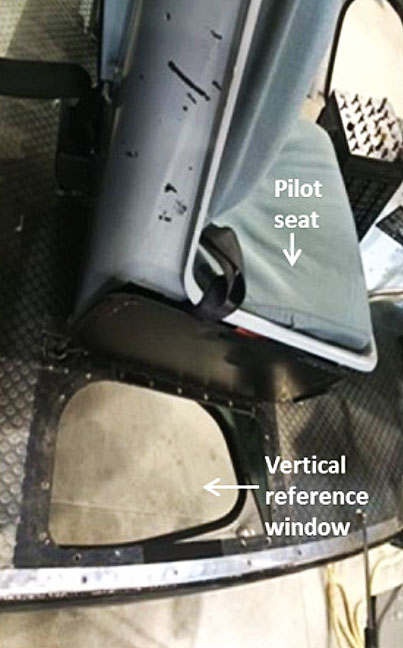
The helicopter was equipped with a 4-point restraint system.Footnote 14 The pilot wore a helmet and was restrained using the lap belt only. The pilot's helmet struck the windshield on impact, but the pilot did not sustain any head injury. The AS350 B2 has a vertical reference window in the floor that serves as a viewer window for the flight crew (Figure 7). This window is to the right of the right-hand pilot seat and has a narrow field of view when looking backward. Pilots can improve their line of sight through the window by undoing the shoulder harness and leaning forward. Although the pilot sustained serious injuries to his back, he was able to evacuate the helicopter without assistance. An inspection of the pilot seat determined that it did not collapse or exhibit any signs of deformation.
Helicopter side pull hooks
Some helicopters are modified to add a side pull hook configuration for conducting Class C operations. The pull hook is mounted to the side of the airframe a short distance from the main rotor thrust vector, offering a better line of sight for the pilot and more stability during pulling operations. A side pull hook installation, even during hard pulling operations, requires less cyclic travel from the neutral position than similar operations using a belly-mounted sling. The side pull modification also incorporates a fusible linkFootnote 15 that will break away if forces at the hook exceed airframe limitations. During an abnormal occurrence, this breakaway component prevents damage to the airframe and allows the pilot time to regain control of the helicopter without having to first jettison the load. At the time of the occurrence, there was no certified side pull installation for the AS350 series helicopter in Canada.
Flight recorders
The helicopter was not equipped with any recording devices, such as a cockpit voice recorder or a flight data recorder, nor were they required by regulation.
Emergency locator transmitter
The helicopter was equipped with a Kannad 406 AF‑H emergency locator transmitter (ELT). The ELT activated on impact, and the signal was received by the Joint Rescue Coordination Centre (JRCC) in Trenton, Ontario. The JRCC made contact with the operator and was advised that first responders were already on site and an ambulance was en route. As a result, the JRCC did not dispatch any search-and-rescue resources. The ELT was deactivated by a first responder.
Safety management and oversight
The Watchlist is a list of issues posing the greatest risk to Canada's transportation system; the TSB publishes it to focus the attention of industry and regulators on the problems that need addressing today.
The TSB urges TC to implement regulations requiring all operators in the air industry to have formal safety management processes and to oversee these processes.
It also calls on companies that have a safety management system to demonstrate that it is working—that hazards are being identified and effective risk mitigation measures are being implemented.
Finally, when companies are unable to effectively manage safety, TC must not only intervene, but do so in a manner that succeeds in changing unsafe operating practices.
TSB laboratory reports
The TSB completed the following laboratory reports in support of this investigation:
- LP024/2015 – NVM Recovery – Load Meter
- LP027/2015 – Examination of Fly Needle
- LP028/2015 – Examination of Hook Release Cable
- LP029/2015 - Examination of Flexible Coupling
- LP030/2015 – NVM Recovery – VEMD
- LP031/2015 – NVM Recovery – GPS
- LP032/2015 – NVM Recovery – Sky Node S200
- LP051/2015 – Video Image Capture and Line Angle Calculation
Analysis
Aircraft
The examination of the helicopter and the data collected during the investigation found no indication of mechanical defects in the helicopter that could have contributed to the occurrence. The analysis will focus on operational issues related to stringing operations, pilot training, and aircraft certification.
Accident scenario
The investigation did not determine a definitive cause of the needle's sudden lunge in the direction of the cable pull and abrupt stop, which are uncommon in normal stringing operations. This may have occurred because the needle contacted the tower steel or the feeder cable caught on a ground obstacle, such as cut trees, deadwood, and large boulders. The pilot had a clear view of the cable and needle through the vertical reference window and did not notice an abnormal increase in tension before the sudden lunge. However, during stringing operations, the pilot is monitoring the load cell reading and is focused on manoeuvring the needle under the insulator string. The aircraft's continued lateral movement with the impeded feeder cable led to the onset of a dynamic rollover, resulting in loss of control and impact with the ground.
Dynamic rollover can occur at any phase of flight when external forces acting on the helicopter create a pivot around a point other than the centre of gravity, such as a snagged skid on take-off or, as in this occurrence, a cable being dragged (Appendix C). The 100 pounds of counterweight in the left side basket and 100 pounds in the left baggage compartment extended the lateral centre of gravity to the left. This additional weight of ballast and a right-hand crosswind would exacerbate the dynamic rollover. During the investigation, it was determined that the abrupt stop and skid contact with the grapple line, combined with the additional weight of ballast and the crosswind from the right, contributed to the onset of the dynamic rollover.
The pilot does not recall whether the electrical hook release was armed before the flight. The pilot had decided that, in the event of an emergency in which the load would need to be jettisoned, he would pull the mechanical release handle. The pilot had flown other types of helicopters in which the electrical release buttons are located in different positions on the cyclic control stick and was concerned that, in an emergency, he would inadvertently press the wrong button.While the decision to release the load with the mechanical release handle did not delay the release of the grapple line during this occurrence, if pilots do not follow normal checks and procedures, there is a risk that the defences that these provide will not be available.
There was communication between the ground crew and the pilot during the feeder cable pull, and there were no reports of increases in cable tension from the ground crew; however, the closest ground crew was 0.34 nautical miles away and unable to see the feeder cable at the occurrence tower. If ground observers cannot adequately monitor Class C loads along the ground, there is a risk that a load may inadvertently snag and compromise safety of operations.
A review of the maintenance page from the vehicle and engine monitoring display (VEMD) provided parameters that are over limits, a list of failures, and a flight report. The VEMD recorded one short torque exceedance (3 seconds), which reached a maximum value of 124%. This is consistent with an abrupt change in collective control during the accident sequence, which was likely the pilot's attempt to arrest the rate of descent.
Training
The company did not provide any practical, hands-on training with feedback, nor did it conduct a check of the pilot's proficiency in stringing operations before authorizing the pilot for operational duties. The limited training and exposure of the pilot to the stringing task meant that the pilot was required to rely primarily on rule-based behaviour to complete the task on the day of the accident. Because performance that is carried out using rule-based behaviour is generally slow, capacity-limited, and effortful, it is more vulnerable than skill-based performance to impairments during stressful or high-workload conditions. The pilot had limited training and experience conducting stringing operations but had successfully completed 10 towers before the accident.
However, there are certain procedures to recover from abnormal situations that might be encountered during stringing operations that cannot be practised in flight, and these are typically only discussed during ground briefings. The required ground briefing was completed, although it was not documented. The investigation determined that the pilot initiated dynamic rollover recovery procedures; however, the pilot lacked hands-on training and experience to identify the onset of the abnormal situation and safely recover in time. If training does not adequately prepare pilots for abnormal flight conditions, there is a risk that pilots may not recognize and correct an unsafe condition in a timely manner.
Aircraft certification
The helicopter was conducting Class C aerial work at the time of the accident; however, it was approved for Class B aerial operations only. A statement in the Rotorcraft Flight Manual Supplement that the cargo hook was approved for both Class B and C helicopter load operations was likely misinterpreted to suggest that the helicopter was approved for Class C operations as well. The Supplemental Type Certificate (STC) does not have any provisions to recertify the AS350 B2 to conduct Class C external loads. Specific approval for Class C loads need to be included in the flight manual or STC supplement before Class C operations are conducted. If approved flight manual supplements are not complete and clear, there is a risk that operators will unknowingly conduct operations that are not approved.
Survivability
In this occurrence, most of the helicopter impact forces were absorbed at the rear of the cabin, owing to the fact that the helicopter landed on a large boulder. This likely significantly reduced the downward forces on the pilot, who was not wearing shoulder restraints. Despite this reduction of downward forces, the pilot's helmet struck the windshield during the impact sequence. If pilots do not use available shoulder restraints, there is an increased risk of injury in the event of an accident.
Findings
Findings as to causes and contributing factors
- The needle suddenly lunged and abruptly stopped, possibly as a result of the needle contacting the tower steel or the feeder cable catching on a ground obstacle, such as cut trees, deadwood, and large boulders.
- The aircraft's continued lateral movement with the impeded feeder cable led to the onset of a dynamic rollover, resulting in loss of control and impact with the ground.
- The abrupt stop and skid contact with the grapple line, combined with the additional weight of ballast and the crosswind from the right, contributed to the onset of the dynamic rollover.
Findings as to risk
- If training does not adequately prepare pilots for abnormal flight conditions, there is a risk that pilots may not recognize and correct an unsafe condition in a timely manner.
- If approved flight manual supplements are not complete and clear, there is a risk that operators will unknowingly conduct operations that are not approved.
- If pilots do not use available shoulder restraints, there is an increased risk of injury in the event of an accident.
- If ground observers cannot adequately monitor Class C loads along the ground, there is a risk that a load may inadvertently snag and compromise safety of operations.
- If pilots do not follow normal checks and procedures, there is a risk that the defences that these provide will not be available.
Safety action
Safety action taken
Transportation Safety Board
On 28 April 2015, the TSB forwarded to Transport Canada Aviation Safety Advisory A15C0005-D1-A1: AS350 Series Helicopter—External Load Certification, which states:
The AS350 series of helicopter can be certified for class “B” external load operations under the authority of an STC. However, although this helicopter series is not certified for class “C” external load operations, discussions with TC and industry operators indicate that the AS 350 series of helicopters are currently being used for class “C” external load operations.
Onboard Systems
On 15 August 2015, Onboard Systems issued a revision to the Rotorcraft Flight Manual Supplement STC SR01165E, Onboard Systems Cargo Hook Sling Suspension System Airbus Helicopters AS350 Series.
Document Number 121-013-00 Revision 1 indicates the following.Footnote 16
2. LIMITATIONS
The limitations specified in the basic flight manual and the Airbus Helicopters “Cargo Sling” flight manual supplement remain applicable and are completed or modified by the following.
Operating Limitations
With a load attached to the cargo hook, operation shall be conducted in accordance with the respective national operational requirements. For US operators 14 CFR part 133 is applicable. The cargo hook kit configurations (as installed per this STC SR01165SE) do not meet the 14 CFR part 27 certification requirements for Human External Cargo (HEC).
Helicopters Ltd.
- Airspan has suspended AS350 helicopter stringing operations until further notice.
- Airspan has reviewed and amended the content of its standard operating procedures (SOPs), including amendments to pre-flight checks, stringing operations, and feeder cable pulling procedures.
- Airspan hired third-party consultants to audit the company's safety management system.
- Airspan has inserted a hazard register for all SOPs.
Valard
Valard has reviewed and revised its SOPs to
- stress the requirement for good communication between ground crew and pilots;
- update the procedure for stringing operations to require pilots and ground crew to monitor the feeder cable pull for snagging debris and for interference as the feeder cable is being strung and before transferring the needle to the opposite side of the structure;
- ensure an adequate number of spotters and placement of ground spotters to monitor the feeder cable pull for hang-ups;
- require all pilots to have completed documentation of their training, orientation, and procedure reviews, and to complete a practical competency check before being allowed to pilot for a particular task;
- require that the foreman and crew lead be informed that a pilot has not performed the particular task with the crew;
- establish a protocol to evaluate the helicopter company and pilots based on the project; and
- ensure that ground crews have been supplied with binoculars.
This report concludes the Transportation Safety Board's investigation into this occurrence. the Board authorized the release of this report on . It was officially released on .
Appendices
Appendix A – Needle
The needle is approximately 37 feet long, weighs approximate 225 pounds, and has 2 pick-up positions, referred to as the front and rear hooks. The feeder cable is attached to the end of the needle. When this method is used for stringing operations, the pilot uses a 30-foot grapple line with a grapple attached to pick up the needle in either of the pick-up positions.
Appendix B – Grapple line assembly
Appendix C – Dynamic rollover