Loss of tail-rotor effectiveness
Highland Helicopters Ltd.
Bell 206B Jet Ranger-III (Helicopter), C-GOPK
Tchentlo Lake, British Columbia
The Transportation Safety Board of Canada (TSB) investigated this occurrence for the purpose of advancing transportation safety. It is not the function of the Board to assign fault or determine civil or criminal liability. This report is not created for use in the context of legal, disciplinary or other proceedings. See Ownership and use of content. Masculine pronouns and position titles may be used to signify all genders to comply with the Canadian Transportation Accident Investigation and Safety Board Act (S.C. 1989, c. 3).
Summary
On 04 May 2016, at 0726 Pacific Daylight Time, a Highland Helicopters Ltd. Bell 206B Jet Ranger-III (registration C-GOPK, serial number 3247) was conducting infrared scanning over a logged area about 112 nautical miles northwest of Prince George, British Columbia, when the helicopter spun uncommanded to the right several times and descended to the ground. The helicopter was destroyed on impact, and all 3 persons on board were seriously injured. There was no post-impact fire. The 406-megahertz emergency locator transmitter activated. The 3 injured occupants were transported to the hospital by another Highland Helicopters Ltd. aircraft that was working in the area.
This report is also available in English.
Factual information
History of the flight
On 04 May 2016 at 0719,Footnote 1 a Bell 206B Jet Ranger-III (Bell 206B) helicopter (registration C‑GOPK, serial number 3247) operated by Highland Helicopters Ltd. (Highland) arrived at cutblockFootnote 2 90072‑1, adjacent to Tchentlo Lake, British Columbia. The pilot as well as a Highland camera operator and a lumber company employee were on board. The helicopter had been chartered by the lumber company to conduct infrared (IR) scans of brush piles burned during the previous winter. The purpose of the scans was to detect any hot spots that might indicate a smouldering fire. A hand-held IR camera was being operated from the passenger seat behind the pilot, on the right side of the helicopter.
Scanning was conducted for about 2½ minutes in the cutblock nearest the lake before the helicopter moved to the 2nd area of the cutblock, about 0.5 nautical miles (nm) southeast of the first area. The 2nd area was also scanned for about 2½ minutes before the helicopter moved to the 3rd area, about 0.5 nm further south. The helicopter flew in the last cutblock for about 26 seconds before yaw control was lost, and the helicopter started rotating to the right. The pilot did not notice any change in tail-rotor authority prior to the sudden loss of yaw control.
It was Highland's practice to conduct scanning operations at about 30 knots ground speed and about 150 feet above ground level to obtain good IR scanning results. The camera was aimed out the open window of the right rear door and was oriented downward about 30° below the horizon. To attain the most efficient photographic coverage of the burn piles, the helicopter flew roughly east-west legs in the cutblocks. Because the wind was coming from the west, this operation meant that the helicopter was flying upwind when flying westbound, and downwind when flying the subsequent (eastbound) legs.
To keep the ground speed constant for the IR camera, the helicopter needed to fly at a higher airspeed when flying upwind, and a lower airspeed when flying downwind. Because the camera was aimed at the ground to the right side of the helicopter, the arc captured by the camera was larger than the arc actually flown by the helicopter when it made a left turn. To allow the camera to capture the ground moving at the correct speed, the helicopter was flown more slowly during left turns than it was during straight-line flight or right turns.
Finally, the pilot flew with a slight nose-left yaw to allow the camera an unobstructed angled‑forward view. This action meant that more left pedal was being used in straight and level flight, and in left turns, than was required for a normal coordinated turn.
Global positioning system (GPS) data (Figure 1) showed that the helicopter's average ground speed during scanning of the first area was about 41 knots. Its average ground speed in the second area was about 34 knots. The helicopter entered the last area at about 27 knots ground speed, and the ground speed decreased steadily thereafter, averaging about 19 knots over the 22 seconds prior to the loss of yaw control.
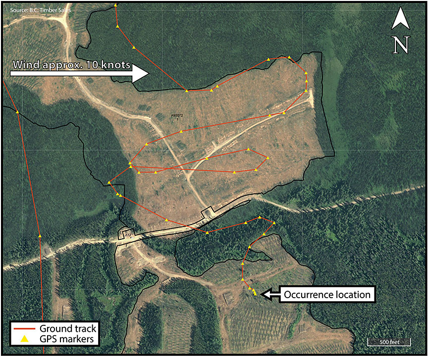
Wind in the area was from the west at about 10 knots. The nearest significant upwind obstruction was standing timber about 1500 feet west (behind the helicopter) when the uncommanded yaw occurred. The aircraft entered the last cutblock flying southwest, flew a gradual left turn through about 105° of arc, and was flying southeast at 14 knots ground speed when the uncommanded nose-right yaw occurred. No unusual sounds or vibrations preceded the uncommanded yaw, and there were no warning lights, horns, or unusual gauge indications. The pilot was unable to attain forward airspeed and, although the collective was lowered and raised several times and full left pedal was used, the spinning did not stop. Over the following 10–15 seconds, the aircraft descended steeply, though not rapidly, to the ground. The aircraft completed approximately 5 complete rotations from the moment when yaw control was lost until, at 0726, it struck the ground. It then bounced once and rolled onto its right side.
All 3 occupants were seriously injured. They were wearing shoulder and lap belts, and the pilot was wearing a helmet. The passengers in the front left and rear right seats were able to exit the aircraft immediately and extricate the pilot, whose head and leg were trapped between the wreckage and the ground. The pilot's helmet likely prevented more serious injuries.
The 406-megahertz (MHz) emergency locator transmitter (ELT) activated during the crash. The Joint Rescue Coordination Centre in Victoria, British Columbia, advised the operator that the ELT on C-GOPK was transmitting, and the operator redirected a nearby Highland helicopter to the accident site to transport the occupants to hospital.
The accident site elevation was 3170 feet above sea level. There is no official weather station at that location. At the time of the accident, the wind was from the west at about 10 knots, visibility was unlimited under scattered cloud, and the temperature was about 5° C.
Aircraft information
Records indicated that the helicopter was certified, equipped, and maintained in accordance with existing regulations and approved procedures. Investigators calculated that the helicopter's weight at the time of the accident was slightly more than 3000 pounds—about 94% of the maximum weight of 3200 pounds—and that its centre of gravity was within the prescribed limits.
The last maintenance on the helicopter was performed the day before the accident and was part of a scheduled 100-hour inspection. That maintenance included lubrication of the splines on the forward end of the tail-rotor driveshaft and lubrication of the driveshaft support bearings. No aircraft defects or abnormalities were noted during that maintenance. During the 2 hours and 26 minutes flown on the day of the accident prior to the uncommanded yaw, the pilot did not notice anything unusual in the helicopter's handling or performance.
The helicopter was equipped with a Latitude S200-011 tracking system and a Garmin 296 GPS. Data from these systems were used to determine the aircraft's flight path and ground speed.
The helicopter was equipped with Van Horn Aviation (Van Horn) tail-rotor blades (part number 2062200-301). The Federal Aviation Administration (FAA) had issued Supplemental Type Certificate (STC) SR02249LA, on 10 August 2009, to allow the original equipment manufacturer (OEM) blades to be replaced with this part, and Transport Canada had issued STC SH10-22 on 07 May 2010. The Van Horn blades were installed on C‑GOPK on 16 November 2015. Since the installation of the replacement blades, the aircraft had flown 28 flights, accumulating 89.5 flight hours.
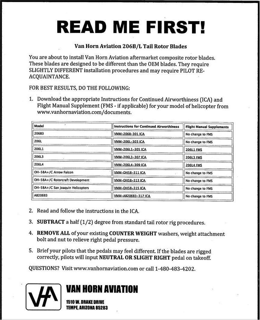
Van Horn blades are constructed of carbon fibre skins over a structural foam core and have a stainless-steel leading-edge abrasion strip. The blades are of nearly the same dimensions as the OEM blades, but are somewhat lighter and have a different airfoil and tip shape. Van Horn promotes its blades as being thinner, quieter, and more efficient than the OEM blades, and describes them as producing "reduced pedal forces."Footnote 3 In the company's FAA-approved documents for installation and maintenance of the blades, the Instructions for Continued Airworthiness state that "the blades have lighter pedal forces in flight."Footnote 4 The "READ ME FIRST!" document (Appendix A) states, in part,
These blades are designed to be different than the OEM blades. They require SLIGHTLY DIFFERENT installation procedures and may require PILOT RE‑ACQUAINTANCE.
[…]
Brief your pilots that the pedals may feel different. If the blades are rigged correctly, pilots will input NEUTRAL OR SLIGHT RIGHT pedal on takeoff.Footnote 5
Wreckage and impact information
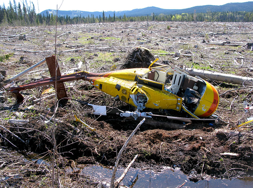
The helicopter was destroyed on impact with the ground (Figure 2). Both main-rotor blades broke several feet outboard of their root ends. The main-rotor gearbox had broken its mounts, and the aft coupling on the driveshaft between the engine and the main‑rotor gearbox had pulled apart. The tail boom remained attached to the fuselage, but was severely bent upward and to the right, about 6 inches aft of the tail-boom-to-fuselage attachment point. The vertical stabilizer (fin) remained attached to the tail boom, but the lower 10 inches of the fin were bent about 90° to the right, and the remaining fin had rotated several degrees counterclockwise as viewed from aft of the helicopter, twisting the tail boom immediately forward of the fin. The upper portion of the fin had been struck by a main-rotor blade.
The tail-rotor gearbox contained an appropriate volume of oil, the components rotated freely, and the magnetic chip plug was clean. The tail-rotor blades remained attached to the hub and spindle and appeared largely intact, but post-crash inspection showed that they were significantly damaged. Inspection established pre-impact tail-rotor control linkage continuity, but correct rigging of the controls could not be established due to extensive airframe damage. However, no tail-rotor abnormalities had been noted by pilots or maintenance personnel prior to the sudden loss of yaw control.
A break in the tail-rotor driveshaft occurred in the forward end of the second driveshaft segment (part number 206-040-931-011), immediately above the bend in the tail boom. An 8‑inch section of the tail-rotor driveshaft had separated, and a 1½‑inch piece of bonded driveshaft coupling had peeled off. The separated section of driveshaft was found on the ground directly beneath the bend in the tail boom, and the piece of driveshaft coupling material was found loose under the tail-rotor driveshaft cover, within inches of its normal location. The "tattle-tale" pinsFootnote 6 in the segment immediately forward of the number 2 bearing hanger remained loose.
Tail-rotor and tail-rotor driveshaft examinations
The tail rotor and segments of the tail-rotor driveshaft were sent to an independent engineering firmFootnote 7 for detailed examinations to determine the extent, type, and cause of the damage found.
The firm's examination found the following:Footnote 8
- Both of the tail rotor blades exhibited extensive damage, which included cracked leading edge abrasion strips, opening up of the trailing edges, and multiple cracks in the blade skins at an angle of approximately 45° to the blade chords and trailing edge tip damage.
- The location of the damage on the tail rotor blades indicated that they were bent in opposite directions.
- The tail rotor blades could be relatively easily bent by hand in the direction of the skin cracking (indicating that there was extensive internal damage).
- The damage on the tail rotor blades is considered to be consistent with the blades striking the ground or an object while being driven under power.
- The tail boom of the helicopter was bent at a severe angle, as a result of ground impact forces, at the location of the failed part number 206‑040‑931‑011 segmented shaft.
- The bearing hanger bracket at the number 2 bearing position was bent forward and the bearing hanger bracket at the number 3 position was bent aft, due to the bending of the tail boom and the compressive load that the tail boom bending applied to the part number 206-040-931-011 segmented shaft.
- The shaft-to-coupling bond on the forward end of the segmented shaft failed in shear in a forward direction due to the shaft being placed in compression as a result of the bending of the tail boom. The shaft was displaced in a forward direction inside the coupling, and the forward end of the shaft was severely rubbed and deformed by contact with the forward inside surface of the coupling.
- The part number 206-040-931-011 shaft was still intact and being driven when the bending of the tail boom was initiated, as evidenced by a deep rotational score mark on the forward face of the number 3 bearing hanger bracket, as well as by relatively symmetrical damage imparted to the forward coupling on the part number 206‑040‑931‑009 segmented shaft. This damage was caused by contact with the disc pack coupling that is installed between the part number 206-040-931-011 shaft and the part number 206-040-931-009 shaft.
- After the shaft-to-coupling bond on the part number 206-040-931-011 shaft failed, the forward end of the shaft was damaged on one side by the rotation of the coupling where the bond had failed, as continued bending of the tail boom caused compressive buckling and/or bending of the shaft. Further bending of the tail boom caused a bending fracture of the shaft, and the thinner part of the failed coupling was peeled away from the assembly during this process. There is no evidence of any rotational damage on the shaft in the area of the bending fracture, indicating that the tail rotor had come to a halt by this point in the accident sequence.
- Microscopic examination of the fracture at the bend in the part number 206‑040‑931‑011 shaft confirmed that it was an instantaneous ductile bending overload with no evidence of any torsional loading being involved in the failure.
The firm concluded the following:Footnote 9
- The failure of the shaft-to-coupling bond at the forward end of the part number 206‑040-931-011 segmented shaft was a result of the bending of the helicopter tail boom caused by ground impact during the accident sequence.
- The tail rotor was being driven when it contacted the ground during the accident sequence, until bending of the tail boom caused the failure of the shaft-to-coupling bond on the part number 206-040-931-011 segmented shaft.
Pilot information
Records indicate that the pilot was certified and qualified for the flight in accordance with existing regulations. The pilot had been employed by Highland for 19 years and had conducted burn-pile scanning every year throughout his employment with the company. He had flown a total of about 22 000 hours, including about 18 000 hours on Bell 206-model helicopters. Approximately 530 of his most recent flight hours had been on Bell 206 helicopters equipped with Van Horn tail-rotor blades.
The manufacturerFootnote 10 and regulatorFootnote 11 have produced information to alert pilots to the phenomenon of loss of tail-rotor effectiveness (LTE). The pilot was exposed to this information during training on the Bell 206 helicopter.
The pilot's most recent pilot proficiency check was conducted on 16 April 2016, less than 3 weeks prior to the accident, and included exercises in managing a stuck anti-torque pedal and in loss of tail-rotor control.
The pilot's work–rest schedule was within the limits set by Transport Canada. He had flown a total of 11.7 hours over the 4 days preceding the accident, 3.4 hours of which were flown on the day prior to the accident. Nothing was found to indicate that the pilot's performance had been degraded by physiological factors.
Loss of tail-rotor effectiveness
According to the FAA Helicopter Flying Handbook, "Loss of tail rotor effectiveness (LTE) or an unanticipated yaw is defined as an uncommanded, rapid yaw towards the advancing blade which does not subside of its own accord."Footnote 12 The handbook explains that LTE is an aerodynamic phenomenon and is not the result of a mechanical failure. It also states that LTE can affect all single-rotor helicopters that use a tail rotor and occurs when the airflow through a tail rotor "is altered in some way, either by altering the angle or speed at which the air passes through the rotating blades of the tail rotor system."Footnote 13
The handbook states, "The design of main and tail rotor blades and the tail boom assembly can affect the characteristics and susceptibility of LTE but will not nullify the phenomenon entirely,"Footnote 14 and adds,
Whenever possible, pilots should learn to avoid the following combinations:
- Low and slow flight outside of ground effect.
- Winds from ±15° of the 10 o'clock position and probably on around to 5 o'clock position
- Tailwinds that may alter the onset of translational liftFootnote 15 and translational thrust hence induce high power demands and demand more anti-torque (left pedal) than the tail rotor can produce.
- Low speed downwind turns.
- Large changes of power at low airspeeds.
- Low speed flight in the proximity of physical obstructions that may alter a smooth airflow to both the main and tail rotor.
Pilots who put themselves in situations where the combinations above occur should know that they are likely to encounter LTE.Footnote 16
Helicopters are uniquely suited for, and therefore often used in, the area of the flight envelope that makes them susceptible to LTE. As well as takeoff and landing, high power and slow speed in a variety of wind conditions are often required for aerial work such as observation, inspection, photography, and slinging. Although it is unrealistic to expect pilots not to fly in this part of the envelope, if LTE occurs, the pilot often has limited time and altitude to diagnose the problem and take corrective action. The accident helicopter was subject to at least 5 of the contributing factors listed above.
The TSB database includes many records of helicopter accidents that involved LTE.Footnote 17
Analysis
General
The damage to the helicopter was consistent with collision with the ground while the main rotor and tail rotor were being driven by significant engine power. The investigation concluded that there were no failures in the helicopter's control systems before it struck the ground. As well, there was no indication that any physiological factors, including fatigue, played a role in the accident. Therefore, this analysis will focus on the aerodynamic phenomenon of loss of tail-rotor effectiveness (LTE).
Loss of tail-rotor effectiveness
To allow the most efficient scanning, the helicopter flew east-west legs, flying upwind on the westbound legs and downwind on the eastbound legs. Consequently, to keep the ground speed constant for the infrared camera, the pilot flew at a lower airspeed when flying downwind. To ensure a consistent ground speed for the camera during left turns, airspeed was reduced further. Global positioning system information shows that the helicopter's ground speed was 14 knots immediately prior to the uncommanded right turn. With a tailwind of about 10 knots factored in, the resulting airspeed was well below the airspeed at which translational lift usually occurs.
The low airspeed, in conjunction with the helicopter's gross weight, resulted in high power demand and high torque. The high torque required high anti-torque pedal input to maintain coordinated flight. As well, the pilot flew with a slight nose-left yaw to allow the camera an unobstructed angled-forward view, requiring yet more left pedal input.
The combination of high gross weight and high power setting while the pilot was manoeuvring at low speed, downwind, and out of ground effect put the helicopter in a flight regime that resulted in LTE. The LTE occurred at a height above ground at which there was insufficient time for the pilot to recover before the helicopter struck the ground.
Findings
Findings as to causes and contributing factors
- The combination of high gross weight and high power setting while the pilot was manoeuvring at low speed, downwind, and out of ground effect put the helicopter in a flight regime that resulted in loss of tail-rotor effectiveness.
- The loss of tail-rotor effectiveness occurred at a height above ground at which there was insufficient time for the pilot to recover before the helicopter struck the ground.
Other findings
- The pilot's helmet likely prevented more serious injuries.
Safety action
Safety action taken
The Board is not aware of any safety action taken following this occurrence.
This report concludes the Transportation Safety Board of Canada's investigation into this occurrence. The Board authorized the release of this report on . It was officially released on .
Appendices