Malfunction of automatic steering control system for right angle drives
Ro-Pax Ferry
Bowen Queen
Gabriola Island, British Columbia
The Transportation Safety Board of Canada (TSB) investigated this occurrence for the purpose of advancing transportation safety. It is not the function of the Board to assign fault or determine civil or criminal liability. This report is not created for use in the context of legal, disciplinary or other proceedings. See Ownership and use of content. Masculine pronouns and position titles may be used to signify all genders to comply with the Canadian Transportation Accident Investigation and Safety Board Act (S.C. 1989, c. 3).
Summary
At around 1820, whilst discharging cars at Gabriola Island, British Columbia, the Bowen Queen spontaneously backed off the dock, causing the shore-mounted vehicle ramp to fall below the level of the vessel's vehicle deck. There was a gap of about four metres between the ferry and the ramp, however the deck crew acted promptly to stop the discharge of vehicles. There was no injury.
Factual information
Particulars of the vessel
| Name | "Bowen Queen" | |
|---|---|---|
| Official number | 323854 | |
| Port of registry | Victoria, British Columbia | |
| Flag | Canadian | |
| Type | Double ended Ro-PaxFootnote 1 Ferry | |
| Gross tonsFootnote 2 | 1476 | |
| Length | 84.96 m | |
| Draught | Forward: 3.3 m | Aft: 3.3 m |
| Built | 1965 - Victoria, British Columbia | |
| Propulsion | 4 Caterpillar diesel engines, 900 BHP each, driving 4 azimuth turning right angle drive propellers | |
| Automatic steering control system |
Mechtronics Technology Inc., Richmond, British Columbia | |
| Cargo | Cars and Passengers | |
| Crew members | 7 | |
| Passengers | 83 | |
| Owner/Managers | BC Ferry Corporation, Victoria, British Columbia | |
Description of the vessel
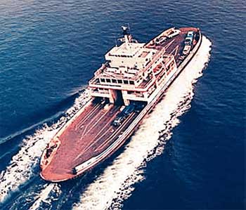
The Bowen Queen is a double ended ro-pax coastal ferry, designed to carry 70 cars on one main deck and 387 foot passengers on two upper decks (see Photo 1). Propulsion and steering is by means of four right-angled drive (RAD) units, one at each corner of the hull. The RADs are of the azimuth turning type, free to rotate through 360° and are independently powered by unidirectional diesel engines, via fluid couplings. They can be directly controlled from two locations in the wheelhouse or from the engine room. When in regular service, the RADs are controlled from the wheelhouse.
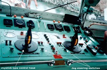
Each wheelhouse control console overlooks its half of the vehicle deck and by means of a 'transfer' switch, becomes the active or 'live' control station. There are two 'joystick' type control heads at each console and one pair of 'end' RADs is controlled by each joystick (see Photo 3). The vessel being double-ended, either console can be used for manoeuvring.
Description of steering control systems
Steering the vessel is effected by rotating the RADs and pointing the propellers in the desired direction. The rotation of a RAD leg is done via gearing and by a hydraulic motor powered by an engine-driven hydraulic pump. The direction of rotation of a RAD unit is controlled by an electro-hydraulic 'proportional' valve, which in turn receives its signals from a control head in the wheelhouse.
The vessel's propulsion and steering system may be operated in either the automatic or manual modes. The manual mode is essentially a back up system.
Automatic control system for right angle drive units
The joystick type control head is used to manipulate the throttle and clutch and can rotate a pair of end RAD units through 360° in the horizontal plane. Pushing the handle forward has the effect of speeding up the engines and propellers; pulling it vertically upwards disengages the clutches; while rotating the handle causes the drive legs to rotate.
By means of suitable gearing, these motions are communicated to transducers which in turn communicate with automatic throttle, clutch and steering control units. A transfer control switch serves to engage or disengage the appropriate control station in the wheelhouse.
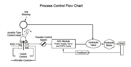
The automatic steering control unit contains 'power supply', 'servo' and 'positive direction process control' printed circuit boards (PCBs or cards), which modulate and convert the input signals into an output signal, which is used to control the hydraulic proportional valves. These hydraulic valves are then used to turn the RAD legs in the required direction.
A feedback transmitter is incorporated in the control process. It provides positional information back to the servo card, where the signals are compared and suitable error signals generated. In this way, the control process is of the 'closed loop' type.
'Manual' or jog steering mode
In this mode, the automatic steering control unit is bypassed and the hydraulic valve is directly controlled by the 'Jog' steering switch (see Figure 1). Each RAD leg has its own jog switch and the switch itself has three positions - the centre position being 'zero' or neutral, while the two positions at either side of the centre rotate the RAD either clockwise or counterclockwise. This rotation is sustained as long as the switch is held in position. The switch is spring loaded to return to its centre, 'neutral' position upon release. This effectively stops further rotation of the RAD.
Alarm system
The steering control system is equipped with audio-visual alarms in both the engine room and wheelhouse, which give warning in the event of failures of the power supply, prime movers, hydraulic pumps or motors.
Description of a typical docking and undocking manoeuvre
The crossing is normally performed at full-service speed, with all four RADs thrusting in the 'ahead' direction. Upon approaching the dock, the vessel is progressively slowed down and aligned, so that it creeps towards the 'vee' formed by the wing-walls of the dock. The two forward RADs are then rotated so that they thrust in the opposite or 'astern' direction. This provides a braking action to the vessel's movement and allows it to come to a gentle stop against the fenders of the dock. The two after RADs are throttled up slightly to maintain a net positive thrust against the dock and the two forward RADs are then re-rotated back into the 'ahead' direction.
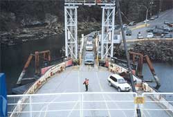
Once all the RADs are pointing in the same 'ahead' direction and the officer in charge of the wheelhouse (OOW) is satisfied that conditions have stabilised, the 'off loading officer' is signalled to prepare for discharge. The shore ramp is lowered onto the vehicle deck by remote control, securing lines are passed between the vessel and the shore and the protective netting across the deck is removed. Foot passengers leave the vessel first, followed by vehicles. The vessel then loads for the return trip.
Upon confirmation that loading has been completed, the shore ramp raised and the securing lines released, the OOW transfers control of the RADs to the other wheelhouse control console for departure. The two joysticks are then rotated simultaneously so that all four RADs move together through 180°; the propellers are now thrusting in the new 'ahead' direction and the vessel proceeds outwards.
History of the voyage
The BC ferry corporation vessel Quinsam is the regular vessel used to provide ferry services between Gabriola Island and Nanaimo, British Columbia. On 04 February 2002 it went in for an extensive refit and was replaced by the Bowen Queen. The regular working crew of the Quinsam had been familiarised on the running of the Bowen Queen and began operating it from February 4 onwards.
At about 1755 on 13 April 2002, the Bowen Queen departed Nanaimo Harbour for the scheduled crossing to Descanso Bay, Gabriola Island. The crossing was uneventful and the vessel arrived at Descanso Bay at 1820. When in position at the dock the master aligned all four RADs in the 'pushing in' direction, the shore ramp was lowered and the discharging of foot passengers and vehicles commenced.
After docking, the master was alone in the wheelhouse and working at the chart table, when the chief officer entered the wheelhouse to relieve him. He checked that the joysticks at both the 'live' and the 'non active' control consoles were in the same angular position and after verifying this, moved toward the chart table, as the master began to descend the wheelhouse stairs.
At this time the chief officer noticed that the vessel was moving astern. He alerted the master who immediately ran toward the 'live' control console to find that the vessel, now some four metres off the dock, had begun moving toward it again, although no one had altered the control settings.
The astern movement of the ferry caused it to part its mooring lines and the shore ramp to fall below the level of the car deck. Three motor vehicles had been discharged and a fourth was on the ramp when the vessel began moving away from the dock. The deckhand in charge of the car deck shouted for the driver of the fourth car to accelerate, allowing it to clear the ramp. Further off-loading was stopped. The deckhand's vigilance and timely action prevented any casualties.
Meanwhile in the wheelhouse, the master had declutched all four RADs, rotated the two forward legs so that they would provide a braking action and then re-clutched them in. The vessel was backed away from the ramp and did not make contact with it. It was then taken about 30 m away from the dock, where the four RAD units were operationally tested to determine the cause of the malfunction. When none was found, the ferry returned to its berth and safely discharged all the remaining cars.
Shore authorities were notified of the incident and, with the vessel in the dock, the ship's crew carried out further tests on the legs and their hydraulic and electronic control systems, in an attempt to determine the cause. No abnormality was found and the vessel resumed its normal operations.
It was estimated that the Bowen Queen had been discharging passengers and cars for about four minutes before it began moving astern and that the time taken for the vessel to back away from the berth and then move towards it again, was about 10 to 15 seconds. It was also reported that the vessel's spontaneous departure from the dock was more rapid than the normal 'controlled' undocking manoeuvre and that the vessel had initially moved sideways and pushed against the port wing wall.
Vessel and crew certification
The Bowen Queen was certificated, equipped and crewed in accordance with existing regulations. Additionally, the BC Ferry Corporation and the vessel held valid certification in accordance with International Safety Management Code requirements.
Analysis
Automatic steering control system
Each RAD unit has its own set of PCBs and transducers and one control head (joystick) controls two RADs. However, both electrically and mechanically, the two RADs are completely isolated from each other. The only common point is the control head itself and the main driving gears, cams and shafts within it.
While the cause of the ferry moving away from the dock and then quickly back toward it again, was not determined, the automatic steering control system has been known to behave erratically on several occasions.Footnote 3 Interviews with the crews of British Columbia Ferry Corporation (BC Ferries) vessels fitted with similar RADs and steering control systems, show that all nine vessels have a similar history.
It appears that these RADs will, suddenly and without warning, spontaneously rotate independently of the command signal. Sometimes the RAD legs rotate through 360° and stop of their own accord, although most times they continue turning until the engine is shut down. There have been numerous instances where one RAD leg has spontaneously rotated. While it is not unknown for two RADs to spontaneously rotate simultaneously, these instances are comparatively infrequent.
The effect of such a rotation on a vessel under way, would be to move the vessel off course. For a vessel in dock, the effect would depend on the number of RAD legs that rotated. The rotation of one leg would just make the ferry move sideways - the net forward thrust would always be greater than that of the rotating leg and the ferry would continue to push against the dock.
The effect of two legs rotating would be dynamic and would change with the changing angular difference between the forward and after pairs of legs. It would also be a function of the thrust being produced at each propeller shaft and of the ricocheting wash off the wing walls of the dock.
Trials were later conducted on the Bowen Queen when the vessel was lined up in dock and all four legs were pushing against it. Both the forward and after pairs of legs were separately rotated and on both occasions it was found that the vessel moved out of the dock. Rotation of the forward legs caused it to move straight out; while rotation of the after legs caused it to first move sideways and bear against the floating wing wall.
Alarm system
The alarm system warns of failures or malfunctions in the power supply and hydraulic circuits. However there is no audio-visual alarm to give warning of a spontaneous deviation between the command signal from the joystick (set point) and the actual position of the leg (measured value). A 'look out' on the bridge would become aware of such a rotation only by its effect on the ship's heading or by looking at the RAD angle indicator.
Safety Management System
An effective Safety Management System (SMS) should include procedures to ensure that accidents, non-conformities and 'near misses' are reported to the vessel's owners and operators and that these are investigated and analysed with the objective of improving safety. Further, procedures should be established for the implementation of the necessary corrective action.
BC Ferries owns nine vessels fitted with RADs and similar automatic control systems, all made by the same manufacturer and all having a similar history of occasional erratic behaviour. The causes of such malfunctions vary and could be due to a variety of reasons; from disruptions in the feedback signal, improper shielding of the cables, defective transducers, faults in the hydraulic circuit, improper isolation and grounding while welding, to defective PCBs, etc.
Interviews with BC Ferries personnel and with the manufacturers indicate that defective PCBs are the most frequent cause of RAD malfunction. According to the PCB manufacturers, the performance of the cards tends to deteriorate with time and it is recommended that they be renewed after they are about 10 years old. While most of the PCBs are fifteen to twenty years old, some are newer and until very recently, they did not have an identification or serial number. There is thus no way of knowing the age, or history, of the majority of the cards.
The SMS requires that there be a planned maintenance system and that malfunctions be analysed, with a view to optimising performance and eradicating failures. At the time of the investigation, neither BC Ferries nor the manufacturer of the PCBs had such a system in place, nor is there any kind of trend monitoring done on the failures. Defective cards, without identification as to the originating vessel, are often sent to the manufacturer indirectly via a central despatching and receiving facility. Quite frequently, a description of the defect that necessitated the card(s) replacement and subsequent repair is not provided.
When a vessel's crew is unable to rectify a RAD malfunction, the manufacturer is called out to effect a repair. Rarely has a report on the work done been submitted to the engineering superintendent's office, or to the vessel's master or chief engineer. An efficient and effective SMS requires the proper documentation of repairs to all critical equipment and for such documentation to be readily available to the vessel's current and future crews.
Findings
Findings as to causes and contributing factors
- Spontaneous rotation of either the forward or after pair of right-angled drive (RAD) units caused the vessel to back off from the dock and return toward it.
- While the definite cause of the RAD malfunction was not determined, information points to the defective printed circuit boards in the automatic control systems.
Findings as to risk
- There is no audio-visual alarm provided to give timely warning of a spontaneous deviation between the command signal from the joystick (set point) and the actual position of the RAD leg (measured value).
- Nine British Columbia Ferry Corporation (BC Ferries) vessels are fitted with RADs and similar automatic control systems made by the same manufacturer and all of these vessels' RADs have a similar history of occasional erratic behaviour.
- At the time of the occurrence, BC Ferries vessels' Safety Management Systems did not require that printed circuit boards were individually identified by serial numbers or that repairs to them were documented.
- At the time of the occurrence, neither BC Ferries nor the manufacturers of the automatic control systems had a planned maintenance system to replace the printed circuit boards.
Safety action
Action taken
- Repairs to the control system of the Bowen Queen were completed during a drydock and refit in September 2002.
- British Columbia Ferry Corporation (BC Ferries) and the manufacturers of the automatic steering control system are in the process of drawing up a comprehensive 'time based' planned maintenance schedule for the PCBs. Components which deteriorate with time have been identified and these will be replaced when they reach the end of their working life. (see Appendix A) It is planned to have the system in place on the Bowen Queen and on the other eight vessels that share system components by July 2003.
- A 'repair log' is being maintained by the manufacturers of the automatic steering control system. PCBs are assigned identification numbers and a record of the defects found and repairs carried out is maintained. Copies are also kept on board the vessels and in the office of BC Ferries' Engineering Superintendent.
- All future defects and problems with the steering control systems on the nine vessels will be documented and tracked.
- To ensure the integrity of the automatic steering controls, a thorough inspection of the entire system and all its components on all nine vessels was done by the manufacturers of the automatic steering control system. In addition, BC Ferries management has retained the services of independent engineering consultants to do a separate review. Their mandate is to establish whether systems problems exist, and whether there are other actions which could improve safety.
This report concludes the Transportation Safety Board's investigation into this occurrence. Consequently, the Board authorized the release of this report on .
Appendices
Appendix A - Maintenance system for electronic cards
| Power Supply Card | |
|---|---|
| Power Capacitor | Replace every five years. |
| Voltage Regulator | Replace every five years. |
| Power Switching Transistor | Replace every five years. |
| Servo Control Card | |
| Power Transistor | Replace every five years. |
| P. D. P.C. Card | |
| Capacitors | Replace every five years. |
| Transfer Control Card | |
| Transfer Relays | Replace every five years. |
| Capacitors | Replace every five years. |
| System Mother Board | |
| Switching Transformer | Every 50000 hours or 10 years whichever comes first. |
| Capacitor | Every 50000 hours or 10 years. |
| Edge Connector | Every 10 years. |


