Engine room fire and subsequent
Failure of the CO2 distribution manifold
Roll-on/roll-off passenger ferry Queen of Surrey
Queen Charlotte Channel, British Columbia
The Transportation Safety Board of Canada (TSB) investigated this occurrence for the purpose of advancing transportation safety. It is not the function of the Board to assign fault or determine civil or criminal liability. This report is not created for use in the context of legal, disciplinary or other proceedings. See Ownership and use of content. Masculine pronouns and position titles may be used to signify all genders to comply with the Canadian Transportation Accident Investigation and Safety Board Act (S.C. 1989, c. 3).
Summary
On the morning of 12 May 2003, while en route in clear and calm conditions from Horseshoe Bay, British Columbia, to Langdale, British Columbia, with 318 passengers and 137 vehicles on board, the Queen of Surrey suffered a diesel oil fire on its No. 2 main engine. The engine room was evacuated and sealed, and carbon dioxide (CO2) gas was released into it. Although immediate failure of the CO2 distribution manifold allowed some of the gas to escape, enough reached the engine room to extinguish the fire. The vessel was then towed to the Langdale ferry terminal, where the passengers disembarked. There were no fatalities.
1.0 Factual information
1.1 Particulars of the vessel
| Name | "QUEEN OF SURREY" |
|---|---|
| Official number | 396048 |
| Port of registry | Victoria, British Columbia |
| Flag | Canada |
| Type | Double-ended, roll-on/roll-off passenger and vehicle ferry |
| Gross tonnage | 6968.91 |
| LengthFootnote 1 | 139.35 m |
| DraughtFootnote 2 | Forward: 5.25 m Aft: 5.35 m |
| Year built | 1981 |
| Propulsion | Two MaK diesel engines, type 12 M551 AK, 11 860 BHP, driving two controllable-pitch propellers (one at each end of the vessel) |
| Cargo | Passengers and vehicles (capacity: 360 vehicles and 1442 passengers and crew) |
| Passengers | 318 |
| Crew members | 28 |
| Vehicles | 137 |
| Owner | British Columbia Ferry Corporation (BCFC)Footnote 3, Victoria |
1.1.1 Description of the vessel
The Queen of Surrey is a double-ended vessel, having a wheelhouse, propeller and rudder at each end, with the engine room being at midships. The two ends are almost identical and, for the purposes of identification, are numbered "1" and "2." This establishes the port and starboard sides of the vessel and the numbering system of the machinery in the engine room (see Figure 1).
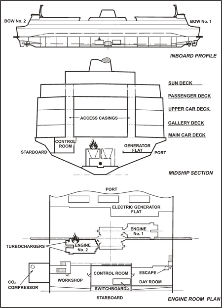
There are three car decks: the upper car deck, the middle gallery deck, and the lower main car deck. The upper and main car decks are accessed from ashore by way of the terminal's ramp systems, while the gallery deck is accessed through ramps from the main car deck.
There are two narrow, vertical casings that extend fore and aft over 60 per cent of the length of the car decks. Each casing is positioned about mid-distance between each side of the ship and the centreline, dividing the upper and main car decks into three continuous roll-on/roll-off (ro-ro) vehicle zones. The enclosed casings provide passengers with sheltered access from car decks to upper recreational areas and passenger service decks. They also provide for the routing of engine exhaust uptakes, the distribution of piping, ventilation and electrical systems, crew access to machinery spaces and operational areas of the vessel, and emergency escape routes.

The engine room contains two main diesel-fuelled propulsion engines, three auxiliary engines for electrical power generation and the associated machinery and equipment. Two propeller/intermediate shafts and reduction gears connect the main engines to the propellers. The shafts are enclosed in "shaft spaces," which can be isolated from the engine room by means of automatic watertight doors.
An engine control room (ECR) is located within the engine room at its starboardFootnote 4 side. It contains the main electric switchboard and the means of remotely starting, stopping and monitoring the main engines and associated machinery. The inboard side of the ECR is fitted with glass windows for viewing various parts of the engine room. The No. 2 main engine, which is closest to the ECR, is clearly visible, although not in its entirety.
The engine room has two entrances from the main car deck; one from within each of the port and starboard casings. The starboard engine room entrance and passageway passes very close to the No. 2 main engine. The ECR can be entered from the starboard side aft by way of the engineers' workshop, as well as from a forward entrance that opens into the engine crew's "day room", where an overhead emergency escape hatch leads directly into the starboard casing on the main car deck.
1.2 History of the voyage
1.2.1 Fire in the engine room
At 0620 Pacific daylight timeFootnote 5 on 12 May 2003, the Queen of Surrey started its scheduled run between its base at Langdale and Horseshoe Bay. A single crossing of the distance of 9.8 nautical miles (nm) takes 40 minutes, and the ferry made three crossings without incident.
At 0923, the vessel departed Horseshoe Bay in clear and calm conditions, on its fourth trip of the day. It had a total of 318 passengers, 137 vehicles and 28 crew on board. There was no marine traffic in the immediate area and, after the engines were set to "Full Away", the master handed over the conduct of the vessel to the chief officer and went down to his office.
At 0932, the third engineer was in the process of carrying out his round of the engine room and, as he approached the No. 2 main engine from its turbocharger end, a spray of liquid was observed shooting upwards and ricocheting off the deckhead and onto the turbocharger casing and engine exhaust. Shortly thereafter, the cloud of spray erupted into flames.
The fire alarm on the smoke detector panel in the wheelhouse sounded, and the bridge was notified that thick black smoke was billowing out of the aft engine room entrance on the main car deck. The master returned to the wheelhouse to take command and sounded the general alarm. The crew members then mustered at their fire stations and the chief officer directed the deck fire party. Passengers were ushered into a safe area, the fire doors in the passenger lounges were closed, and the ventilation system was shut down. Marine Communications and Traffic Services (MCTS), the Canadian Coast Guard, and the Horseshoe Bay and Langdale ferry terminals were advised of the fire.
Meanwhile, as the flames in the engine room grew rapidly, the fire became intense. Observing the scene from the ECR window, the chief engineer immediately alerted the wheelhouse, shut down the main propulsion engines, generators and ventilation fans, and ordered the engine room evacuated. The time was then 0937, just five minutes after the fire was first noticed.
Due to the intense heat around the No. 2 main engine, both engineers left the ECR using the emergency escape hatch to the main deck. Smoke restricted visibility on the main deck, and portable very high frequency (VHF) radios were used for communication between the master in the wheelhouse and other officers on board.
At approximately 0943, following consultation between the chief engineer and the master, a decision was made to flood the engine room with carbon dioxide (CO2) gas from the fixed fire-smothering system. The fuel supply valves to the engines and the ventilation dampers were closed from their remote locations and, with the engine room cleared of personnel and effectively sealed off, the release of the CO2 was activated from the starboard side remote station.
By that time, the heat from the engine room could be felt on the main car deck directly above and the sprinkler system was activated to prevent secondary fires from starting in the parked cars.
1.2.2 Release of CO2
The remote release station for CO2 is located beside the starboard engine room entrance on the main deck and above the CO2 compartment, where the cylinders of compressed gas and their discharge control mechanism are located. A watertight hatch on the main deck provides vertical access to the CO2 compartment below.
As the remote release handles were pulled, a loud bang was heard from the CO2 compartment and the manhole cover over the hatch burst open. (Investigation later revealed that it had been insufficiently dogged down.) It was seen from above that the CO2 distribution manifold had fractured and, as a result, some of the contents of the CO2 cylinders had discharged into the CO2 compartment itself.
Some sprinkler system water vaporized as it sprayed onto the hot main car deck, particularly in way of the No. 2 main engine. However, as the evaporation ceased, it became evident that sufficient gas had made its way into the engine room to extinguish the fire.
1.2.3 Return to Langdale
At 0939, MCTS was requested to arrange tug assistance for the vessel. Accordingly, the Rescue Co-ordination Centre tasked the ferry Queen of Capilano, together with the tugs Seaspan Cavalier and Seaspan Crusader, to assist.
With no propulsive power, the Queen of Surrey lost speed and started to drift towards Finisterre Island, approximately three miles from the Horseshoe Bay terminal (see Appendix A). Anchors were prepared for immediate deployment, if required. The Queen of Capilano arrived on the scene at 1001, and a line was secured between the two vessels.
The Seaspan Cavalier arrived at 1110 and was secured to the Queen of Surrey. The second tug, Seaspan Crusader, arrived at 1138 and the tow to Langdale commenced.
During the tow, the boundaries of the engine room were monitored and no increases in temperature were noted.
At 1339, the vessel docked at the Langdale terminal. After all the passengers disembarked, members of the Langdale fire department, along with two of the ship's engineers, entered the engine room to ensure that the fire had been extinguished. Passengers who had vehicles on board were then permitted to reboard the ferry and drive them off.
1.3 Exhaust and fuel oil systems of the main engine
Each vee-type main engine has 12 cylinders arranged in two banks (A and B) of six cylinders each. The exhaust manifolds from each bank are situated inside the recess formed by the vee, leading to two turbochargers located at the free end. The exhaust pipes are designed to be covered by fire-retardant lagging, with the entire arrangement enclosed under a thermal heat shield.
A daily service tank provides each engine with diesel fuel oil, which is piped through an independent electrically driven booster pump and led, through filters, to a low-pressure fuel rail. Branch pipes from the fuel rail lead to individual jerk-type fuel pumps for high-pressure feed to the fuel injectors.
The low-pressure fuel rail of mild steel pipe has various gauges connected to it by way of tubing of appropriate material with threaded compression connections to steel "bosses" welded to the fuel rail. The fuel oil pressure gauge connection is located at the engine's turbocharger end and is fitted with a shut-off cock at the pressure gauge.
After the fire, an inspection revealed the following:
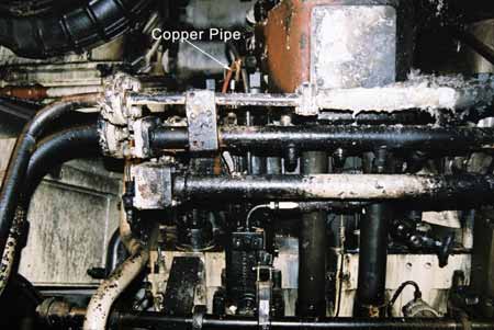
- the fuel oil pressure gauge pipe, attached to the compression fitting on the A bank, was made of copper and had fractured;
- the high-pressure fuel pipes were jacketed, whereas the low-pressure fuel rail was not;Footnote 6
- the thermal heat shields, which should have been arranged on top of the exhaust manifold of the main engine, were missing;
- the exhaust pipes were inadequately lagged.
1.4 CO2 smothering system
The vessel is fitted with a fixed, total gas flooding installation for extinguishing engine room fires, the firefighting medium being CO2. Requirements for the construction, inspection and testing of such a CO2 system are specified in the Fire Detection and Extinguishing Equipment Regulations made pursuant to the Canada Shipping Act (CSA).
1.4.1 CO2 storage compartment
The CO2 compartment, aft of the engine room below the starboard side main deck casing, contains 53 steel cylinders or "bottles" of pressurized CO2. Access to the compartment is through a circular hatchway on the main deck, which can be sealed off by means of a quick closing weathertight hatch cover. The hatch is normally kept closed.
The compartment has two ventilation trunks: a forced draft exhaust and a supply. Each trunk is fitted with three flap-type dampers (two fusible-link type and one manually operated), the closing of any one of which enables the CO2 compartment to be isolated. A fusible-link damper in the supply trunking was found to be closed, the link having been broken at some indeterminate time in the past.
1.4.2 CO2 distribution manifold
The CO2 cylinders were arranged in three banks, rigidly clamped to the outboard, forward and inboard bulkheads of the CO2 compartment. Each cylinder was connected to a distribution manifold by means of a flexible, reinforced, braided neoprene hose, which formed an inverted U between the top of the cylinder and the piping. The distribution manifold was made up in sections of sub-manifolds and branches, all constructed out of threaded, galvanized, schedule 40 steel pipe (or schedule 80, depending upon its diameter). An overhanging arrangement of steel frames and brackets was welded to the bulkheads, and it held the distribution piping by means of U clamps, which were passed around the pipes and bolted to the brackets (see Photo 2).
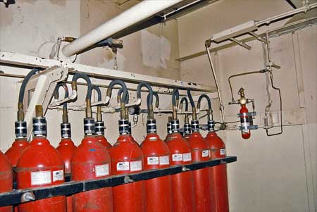
The arrangement of CO2 cylinders was comprised of four master cylinders and 49 slave cylinders, each containing about 45 kg of liquid CO2 at a pressure of 6300 kPa (at 24°C). Two of the master cylinders were fitted with manually operated valves, which could be opened from either within the CO2 compartment or from remote CO2 release stations (see Appendix B).
The slave cylinders were fitted with non-return check valves, which were opened by the action of spring-loaded plungers. These, in turn, were depressed by the back pressure of the CO2 when it was released into the discharge manifold from the master cylinders.Footnote 7 A stop valve separated the master and slave cylinders and effectively isolated them from each other. This valve had a similar pull-cable arrangement to the master cylinders, and it too could be operated either remotely or locally from within the CO2 compartment.
A time-delay unit was also built into the master side of the system and its function was to delay the release of CO2 for 25 to 30 seconds, to allow personnel time to evacuate the engine room safely. Automatic audio alarms to alert the crew to an impending discharge, electrical stop switches for shutting down fuel oil pumps, and vent fans were also incorporated into the system via pressure transducers attached to the time-delay unit.
1.4.2.1 Condition of the distribution manifold
The condition of the CO2 distribution manifold at the time of the occurrence was as follows:
- various stub pipe sections showed strong evidence of having been "chewed" into by a pipe-tightening wrench;
- some sections were misaligned at their couplings;
- at other places, the threads on some couplings were broken; and
- the hoses were bent into many different radii.
1.5 Requirements for structural fire protection
The Hull Construction Regulations, Part III, of the CSA, define the degree of fire-retardant insulation required on the bulkheads and decks of different compartments aboard a vessel, and/or the utilization of sprinkler systems as a means of managing the fire risk inherent in these compartments. These regulations were introduced in 1958 and were based on the 1948 International Convention for the Safety of Life at Sea (SOLAS). Subsequent SOLAS conventions and amendments further improved the requirements for structural fire protection, but the Hull Construction Regulations have not been amended to reflect these improvements.
In 1979, Transport Canada (TC) published TP 2237, Equivalent Standards for Fire Protection of Passenger Ships, to reflect modern concepts in structural fire protection and include the latest requirements of the SOLAS at that time. The Board of Steamship Inspection considered these standards to provide a level of protection equivalent to the provisions of the Hull Construction Regulations, Part III. Shipowners were therefore given the option of having their vessels constructed in accordance with either the existing regulations or the equivalent standards. TC is currently reviewing the regulations under the regulatory reform agenda.
1.5.1 Structural fire protection around the engine room
On the Queen of Surrey, the deckhead of the engine room (which formed part of the semi-enclosed main car deck) was of non-insulated bare steel. A sprinkler system fitted over the deck above was the means of limiting the propagation of the fire.
1.6 Safety Management System
Although not required to comply with the requirements of the International Management Code for the Safe Operation of Ships and for Pollution Prevention (ISM Code), BCFC had voluntarily elected to obtain a Document of Compliance for its fleet and a Safety Management Certificate for the Queen of Surrey.
In accordance with the ISM Code, the company had developed a Safety Management System (SMS) for the Queen of Surrey. This SMS, among other things, required vessel inspection and planned maintenance routines to be drawn up and implemented, as well as contingency plans and procedures for dealing with various potential shipboard emergency situations. A program of drills and exercises, to enable the vessel's crew to efficiently deal with such situations, had also been developed. These procedures were all maintained in the vessel's ship-specific manual and the operations/current orders manuals.
1.6.1 Inspection, planned maintenance, and repair procedures
An inspection of the engine room, main and auxiliary engines, was required to be done periodically by engine room watchkeepers. The items to be checked and the nature of the checks were specified in checklists drafted pursuant to the ship's SMS. Recognizing that checklists for engine room operations could not enumerate every detail, the watchkeeping staff was also required to use their experience, knowledge and training to advantage.
The planned maintenance routines for the main engines required them to be dismantled and overhauled on the basis of "running hours", and different routines had been established for different components. Depending on the extent of the work involved, these were done either by ship- or shore-based workshop staff.
Additionally, defects of the running machinery noticed during inspection rounds were brought to the chief engineer's attention, who, after evaluation, noted them in an engine room daily defect sheet. Defects that could not be rectified during the operational time of the vessel were attended to by the night maintenance shift while the vessel was alongside. Descriptions of the work done and significant events noted during a shift were entered in a computerized fleet-wide planned maintenance database called Maximo. These were supplemented by a verbal exchange of information between adjacent outgoing and incoming shifts. The comments in the defect sheet and Maximo also served to provide a feedback loop between the person rectifying the defect and the person noting it.
The leaking pressure gauge connection on the No. 2 main engine had first been identified on May 10, two days before the occurrence. It was tightened by the engineers on the morning shift and, when that did not prove effective, it was noted in the defect sheet for attention by the night-shift staff. Along with the request for repair, a notation was also made that the connection "did not feel right" when it was being tightened.
Further, the entire CO2 storage, distribution and activation system was required to be routinely inspected by the ship's staff. However, such inspections were not conducted on a regular basis.
1.6.2 Training of ship's staff and supervision of maintenance tasks
All of the vessel's crew members held the appropriate TC certificates of competency for their rank. BCFC had also developed a training program for its officers and crew whereby, depending on their rank and the type of vessel, they were trained in various subjects, including the ISM Code. The senior engineers were also required to attend a course in "supervisory safety". This training course was designed to increase occupational safety awareness and safe work practices, and its syllabus covered subjects such as safety responsibilities and duties, industrial hygiene, machinery and plant inspections.
The vessel's senior engineers were required to train and instruct their juniors in good engineering and safe working practices, but BCFC had not developed any formal on-the-job training programs to this end. The expectation was that these would be imparted to the juniors by the senior engineers in their supervisory role, during the day-to-day operation and maintenance aboard the vessel.
The first engineer was responsible for the direct supervision of maintenance tasks carried out during his shift. While the first engineers on the morning and afternoon shifts reported to the senior/chief engineers, the night maintenance shift did not have a chief engineer. The first engineer was responsible for this shift and all the work carried out during it. The first engineers met and could discuss events during the change-over from one shift to the next. (The chief engineers, having staggered watch timings, arrived later and, consequently, did not meet the first engineers coming off the night shift.)
1.6.3 Emergency preparedness aboard the vessel
The company had developed procedures for effectively dealing with various identified emergency and safety-critical situations aboard the vessel. However, no plans had been developed for the safe evacuation of passengers and non-essential crew when the vessel, in a state of emergency, was alongside.
1.6.4 Passenger safety
In this instance, when the fire alarm was sounded and soon after arriving back in the wheelhouse, the master, in consultation with the senior officers aboard, made occurrence-specific plans to safeguard the vessel, its passengers and crew against the different identifiable contingencies, with reference being made to appropriate manuals.
The passengers were mustered in a lounge area, away from the scene of the fire, and were kept informed of the situation. Lifejackets were also prepared for issue to the passengers, to be used under instruction and only if required.
Before the vessel docked at Langdale, there was discussion with the terminal about the correct disembarkation protocol to adopt, considering that the vehicles contained substantial quantities of gasoline, which presented a risk of fire and explosion. An evacuation plan was prepared for the passengers, and arrangements were also made for the local volunteer fire department, paramedics and ambulance services. Tow trucks and police were to be present when the ferry docked.
1.6.5 Analysis of accidents and non-conformities
The ISM Code requires that the SMS incorporate procedures for the master to report accidents, hazardous occurrences and non-conformities to the designated person ashore. These are then required to be investigated and analysed, and suitable corrective action has to be taken to prevent their recurrence.
BCFC had accordingly developed such procedures and defined different levels of severity for ship-board incidents. Masters were required to report them to the appropriate person representing the company's shore-based management, depending on the operational division of the fleet to which the vessel belonged. Depending on the level of severity of the occurrence, it would then be investigated by a panel of suitable senior managers.
The chairperson of the investigating panel was required to produce an inquiry report, including recommendations to avoid a recurrence. This would be distributed to all the managers and superintendents in the fleet.
1.6.6 Role of the designated person
To ensure that the SMS was effectively implemented, audited and periodically reviewed, BCFC had appointed a designated person (DP), as per the ISM Code. The DP's responsibilities included:
- reviewing the findings of internal investigations into accidents and making recommendations for corrective action required;
- ensuring the monitoring and "close out" of corrective action requests; and
- auditing for continued compliance.
1.6.7 Corrective action procedures
Recommendations arising out of investigations and inquiries required appropriate corrective action to be taken within a specified time frame. The corrective action required was implemented by a designated "office of primary interest", which had the responsibility of ensuring the completion of the necessary work, while progress was tracked and monitored by the operational safety superintendent.
1.6.8 British Columbia Ferry Corporation's investigation into the engine room fire and recommendations
An internal inquiry held on 13 May 2003 issued 14 recommendations, 13 of which had fleet-wide relevance, and their implementation was assigned to different offices of primary interest. As required by the SMS, the Operational Safety Superintendent produced a recommendation tracking document that maintained the 30-, 60- and 90-day status of the recommendations.
The DP was not part of the investigative process, and the ensuing recommendations were not made into corrective action requests, per BCFC's SMS.
1.7 Regulatory surveys and inspections
The Queen of Surrey was required to undergo annual hull and machinery surveys by its classification society, Lloyd's Register of Shipping (Lloyd's), as well as statutory annual safety equipment and safety construction surveys by TC. Under the system in use at the time of the accident, TC and Lloyd's carried out joint annual and continuous surveys, while TC carried out the statutory surveys. Under TC's and Lloyd's continuous machinery survey program, the No. 2 main engine was required to be surveyed once every five years.
The Fire Detection and Extinguishing Equipment Regulations, made pursuant to the CSA, and SOLAS's International Code for Fire Safety Systems specify the requirements for the national and international construction, inspection and testing of a CO2 smothering system and distribution manifold. However, being a non-Convention ship, the Queen of Surrey did not have to comply with the SOLAS requirements. The complete installation is required to undergo an annual inspection, at which time the operating gear, gas distribution system and all audible alarms are to be examined and tested by TC inspectors. However, authorized third-party subcontractors.could also perform this function and carry out the necessary repairs, with their reports being accepted by TC. On the Queen of Surrey, several different subcontractors had been given this responsibility over the years.
1.8 Previous similar occurrences
The Transportation Safety Board of Canada (TSB) has investigated other instances of engine room fires caused as a result of diesel oil spraying onto hot engine exhaust manifolds,Footnote 8 and TC has issued two Ship Safety Bulletins (SSB 13/1985 and SSB 08/2000) in this regard. These bulletins are distributed to the marine community at large, through a voluntary distribution list, and they serve to alert the end users to issues TC considers significant. The SSBs are also circulated among TC inspectors for their instruction and guidance, and are available on the TC Web site.
Both SSB 13/1985 and SSB 08/2000 strongly recommend that attention be given to the following:
- the integrity, vulnerability to damage, and wall thickness of fittings, during inspection of fuel, lubricating and hydraulic oil piping installations;
- the possibility of fitting shields at connections, to contain or deflect oil spray in the case of breakage and drainage of any leakage to a drip tray;
- the fitting of sheathing around lagging if there is a possibility of it being subjected to oil leaks from any source;
- the frequent checking of the condition of lagging, oil pipework and fittings; and
- any maintenance or replacement of fuel and lubrication oil pipework or components is to be accomplished with due regard to the potential hazards involved and using replacement parts that comply with the specifications for the systems or the components.
1.8.1 Action taken by British Columbia Ferry Corporation upon receipt of Ship Safety Bulletins
The SSBs are received by either the library or the documentation control department at BCFC's management headquarters in Victoria. Photocopies of these are sent to the company's various local management offices, with two copies provided to every vessel in the fleet. One each is sent to the wheelhouse and the engine room, and a signed acknowledgement of receipt form is then sent back to management at headquarters.
BCFC has not developed any formal follow-up procedures in this regard and any action taken (or expected), subsequent to the receipt of the SSB, is left to the discretion of the fleet superintendents or the vessel's senior staff. Aboard the vessels, the SSBs are received by the senior master and senior chief engineer, who may then choose to disseminate the information contained therein to the other ship staff and also take such appropriate action as may be relevant to their vessel.
1.9 Damage
1.9.1 Engine room and No.2 engine
There was considerable fire and heat damage to the electrical cables that were laid out along the engine room deckhead, and large sections of these had to be renewed (see Photo 3).
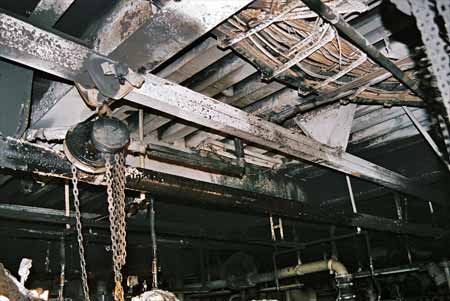
1.9.1 Engine room and No. 2 engine
There was considerable fire and heat damage to the electrical cables that were laid out along the engine room deckhead, and large sections of these had to be renewed (see Photo 3).
The outboard air cooler on the No. 2 main engine was badly damaged such that the collapse of the tubes allowed sea water ingress into the cylinders, and the entire engine had to be overhauled.
The engine room and No. 2 main engine suffered from soot deposit. They required extensive cleaning and had to be repainted.
1.9.2 CO2 compartment and distribution manifold
There was some localized buckling of the deck and deckhead of the CO2 compartment, and some of the welded seams on the stringers and frames separated from the deck plates.
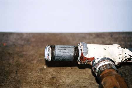
Examination of the CO2 distribution manifold revealed that:
- the free ends of the flexible hoses had flailed around and caused some impact damage to the insulation on the after bulkhead of the CO2 compartment; and
- manifold segments had fractured and sheared off at five different points (see Photo 4).
The fractured pipe segments were sent to the TSB Engineering Laboratory for analysis.Footnote 9 The examination under a scanning electron microscope confirmed that failure was due to fatigue pre-cracking, initiated at the thread root and probably as a result of excessive vibrations.
1.9.3 Main car deck
There was some buckling of the starboard side of the main car deck in way of the engine room.
2.0 Analysis
2.1 Cause of fire
2.1.1 Failure of the fuel oil pressure gauge pipe at No. 2 main engine
All gauge connections originally provided by the engine manufacturer were of steel. However, the steel pressure gauge pipe had been replaced by a copper one at some time in the past.
Copper has a lower melting point than steel, and its tendency to become brittle with time and usage makes it unsuitable for use in fuel oil systems. The Marine Machinery RegulationsFootnote 10 require all such piping to be of steel.
The compression fitting that connected the failed pressure gauge tubing to the fuel supply rail had developed a leak on 10 May 2003, two days before the occurrence. It had been repaired by tightening the compression nut a little further. TSB's Engineering Laboratory analysis of this fitting and the failed copper pipe determined that failure was due to overstress extension from fatigue pre-cracking at the outer diameter, probably as a result of vibrations.Footnote 11 A ring around the outer diameter of the tube suggested that it had been partially cut, perhaps during the installation or tightening process.
Engine-generated vibrations would cause the copper tube to work-harden and extend the partial cut in the now brittle tube wall in way of the compression ferrule, which was already biting into the outer surface of the tube and producing an area of high stress. This cut allowed some fuel to leak, and the engine room staff, under the mistaken impression that the leakage of fuel was from a loose connection, then further tightened the compression nut, driving the ferrule deeper into the wall of the tube.
The leakage was temporarily stopped, but two days later the copper tube completely parted and sprayed diesel oil onto the hot exhaust manifold of the engine.
Improper material, together with transmitted engine vibrations, thus led to the failure of the pressure gauge connection tubing, at an area of raised stress concentration in way of the compression ferrule inside the compression fitting.
2.1.2 Fuel oil pressure gauge connection
The Marine Machinery Regulations require that fuel pipes and branches be arranged so that spills and leakages are not directed at heat sources.Footnote 12
In this case, the pressure gauge connection pointed upwards towards the turbocharger gas inlet casing and the engine room deckhead (see Photo 5). This allowed the leaking fuel to come into contact with the heat source. Other take-offs from the fuel supply rail pointed downward, towards the engine foundation.
Thus, the improper orientation of the pressure gauge connection take-off point directed pressurized diesel oil from the fractured pressure gauge pipe to spray onto the hot engine exhaust manifold.
There was a fuel oil inlet valve on the engine and another valve on the return line from the engine to the service tank, but there was no direct means of immediately isolating the pressure gauge connection at the fuel rail, nor is one required. Without a direct means of interrupting that leak, the only other way to do so was by stopping the engine and shutting its fuel inlet and outlet valves. However, current Marine Machinery Regulations do not address the means of immediately restricting, containing or redirecting the flow of pressurized flammable fluids from ruptured low-pressure pipe lines.
2.1.3 Fire on No. 2 main engine
It was found that the thermal heat shields, which should have been arranged on top of the exhaust manifold of the main engine, were missing. The heat shields had originally been part of the engine-mounted equipment, but reportedly had been removed in 1997 to facilitate easy and unhindered disconnection and assembly of the exhaust pipes from the cylinder heads.
These shields were intended to cover the exhaust pipes all the way up to the gas inlet manifold of the turbocharger and act as a barrier against anything combustible from coming into direct contact with the hot exhaust surfaces. The absence of the heat shields rendered this safeguard ineffective.Footnote 13
The entire exhaust manifold was designed by the manufacturer to be covered by fire-retardant insulated lagging. While it extended over the length of the exhaust pipes, the lagging was found to be damaged at various places. Also, in way of a short section of piping at the inlet connection to the turbocharger, this lagging was completely missing.
The average running exhaust temperatures at the cylinder outlets and at the outer surface of this exposed, bare section of the exhaust pipe was between 400°C and 450°C. The jet of pressurized diesel from the fractured tubing sprayed onto both the hot turbocharger exhaust gas inlet casing, as well as this unlagged section of hot exhaust manifold, where it vapourized and then rapidly ignited.Footnote 14
The "clean burn" areas created by the high-intensity flames and the "shadowing" patterns created by the deposition of soot on the turbocharger air inlet casing, engine piping and cable trays located on the deckhead indicate the origin of the fire to be in between the turbocharger casing and the last cylinder on the engine's A bank (see photos 3 and 5).
While the presence of a heat shield and suitable lagging around the exhaust and turbocharger gas inlet manifold may not have prevented the fire, it may have delayed its onset, thereby providing an opportunity for suitable remedial action.
2.2 Structural fire protection around the engine room
2.2.1 Engine room deckhead
The engine room contains many combustible substances and sources of heat, making it particularly susceptible to the risk of fire. However, by adopting proper design techniques and operational practices, the risk of a fire spreading to adjacent compartments can be minimized.
The deckhead of the engine room of the Queen of Surrey forms a portion of its main car deck where parked vehicles containing gasoline tanks present a significant fire hazard. This can be mitigated by offering a thermal time-delay by fitting fire-retardant insulation as a barrier against the immediate transfer of heat. This delay provides an opportunity to both combat the fire in the engine room and further control the transfer of heat by appropriate boundary cooling. This is recognized in TC's TP 2237 and in the SOLAS,Footnote 15 which refer to having the boundaries of the engine room insulated to A-60 standards, which would offer a 60-minute thermal delay.
The engine room deckhead of the Queen of Surrey was constructed to A-0 standards (painted, bare steel), in accordance with applicable regulatory requirements. Consequently, the transmission of heat from the fire in the engine room was rapid and allowed the temperature of the car deck to rise. This exposed the vehicles parked there to the risk of fire.
2.3 Release of CO2 and failure of the distribution manifold
There were insufficient clamps between the various branches of the manifold piping and the supporting framework, which left entire subsections unsupported and attached to their distribution pipes at just one end. Each unsupported pipe section also had two CO2 cylinders connected to it via flexible, high-pressure, braided, neoprene inverted U-shaped hoses.
The unsupported pipes could thus be considered as cantilevers, with one end rigidly secured, the other end free, and loads applied at two points along their length. These loads produced bending moments and shear stresses on the pipe sections, as the flexible hoses had a natural tendency to "open" and revert to their straight form. The loads also had a torsional component, since the flexible hoses did not lie in the same axis as the pipes.
The vessel was found to have considerable vibrations during docking and undocking, which were then transmitted to structures within the vessel. In the cantilevered arrangement of the sections of the manifold, induced vibrations of large amplitude would have occurred at the free ends of the pipe sections. This cyclic loading, over time, produced localized cracks as a result of fatigue failure, at areas of stress concentration, such as at the thread roots.
When the CO2 release handles were pulled, pressurized CO2 (at about 6300 kPa) entered the flexible hoses, manifold sections and distribution piping. The applied loads and bending moments on the unsupported cantilever pipes increased instantly, causing sections that had already developed pre-cracks as a result of fatigue to fail. This caused a quantity of CO2 to escape into the CO2 compartment. However, sufficient CO2 reached the engine room to extinguish the fire.
2.4 Adequacy of standards for construction and testing of CO2 systems
2.4.1 Design of the CO2 distribution manifold
The CO2 systems are designed to the requirements of the Fire Detection and Extinguishing Equipment Regulations. Among other things, the safety provisions contained in these regulationsFootnote 16 require that:
- the release of CO2 into a machinery space be possible only by the opening of a stop valve and a control valve, and
- means shall be provided for giving audible warning within a space in which personnel work or have access to.
In the type of arrangement that was fitted aboard the Queen of Surrey, there was no means of isolating the slave cylinders from the main supply pipe into the engine room. The four master cylinders were separated from the 49 slave cylinders by a stop valve, the only purpose of which (by means of a time-delay function) was to allow the crew in the engine room sufficient time to evacuate it.
Consequently, there was no safeguard against a potentially hazardous condition whereby the contents of one or more slave cylinders could have leaked past a check valve and into the engine room - without activating the audible alarm, and exposing personnel and the vessel to undue risk.
The CO2 release alarm for alerting engine room personnel of imminent CO2 flooding was electrically operated by means of a pressure switch connected to the master side of the distribution manifold. In such a leakage scenario, since the stop valve between the slave and master cylinders would be closed, the CO2 warning alarm would not be activated, giving the engine room staff no indication that one or more cylinders were leaking into the engine room.
Because of the dispersion effect of the engine room's ventilation systems, a small leak does not pose much danger to personnel, unless it leaks into a small enclosed compartment such as an ECR. It does, however, reduce the net quantity of CO2 available for extinguishing a fire. Since there is no indication that a leak has occurred, the engine room staff would remain unaware of it until the next check or the CO2 cylinders' contents were used.
While the Fire Detection and Extinguishing Equipment Regulations require that a means be provided for suitable audible warning when smothering gas is about to be released, they do not require a means of preventing the inadvertent discharge of this medium from entering a space. In the design of the CO2 installations, such as on board the Queen of Surrey, manufacturers met the requirements of the regulations, since CO2 could only be intentionally released by opening the stop valve, but the design could not safeguard against the accidental release.
The hazards to personnel and a vessel associated with an unwanted release of CO2 into the engine room have been recognized by the International Maritime Organization in the SOLAS regulations,Footnote 17 which require that the system be designed to safeguard against it. However, as a non-Convention ship, the Queen of Surrey did not have to comply with the SOLAS.
2.4.2 Method of design, fabrication, and approval of the CO2 distribution manifold
The integrity of a CO2 distribution manifold, and its consequent ability to convey a firefighting medium to the scene of the fire, may be jeopardized by one improper pipe connection.
A performance-based regulation takes into consideration the risks associated with individual operation. It provides the owner, the regulator, and the manufacturer with the flexibility to tailor the product to meet the varying needs of the user, while providing an acceptable minimum level of safety. Also, because it permits continuous design improvement due to technological progress, it has the potential to raise the threshold of safety. The Fire Detection and Extinguishing Equipment Regulations for the design of the CO2 distribution manifolds are performance-based and specify the criteria the system must conform to. Thus, minimum bursting pressures, corrosion-resisting properties, time required to fill a space, etc. are specified, but not the metallurgical properties of the pipes, their required diameters, or the method of determining volumetric flow capabilities through orifices and diffusers.
To design a CO2 system that meets the requirements of the Fire Detection and Extinguishing Equipment Regulations, manufacturers use the rules and guidelines set out by the National Fire Protection Association (NFPA).Footnote 18 The finished drawings and calculations are then submitted to TC for approval, after which the system is fabricated and installed aboard a vessel. TC uses the NFPA guidelines to verify the calculations.
Aboard the Queen of Surrey, the entire distribution manifold, including the main supply pipe into the engine room, was constructed out of galvanized steel pipe of various diameters. The ends of pipe sections had threads cut into them, and they were fitted into straight, T or 90° elbow threaded fittings and connectors, to make up the assembly.
The threads on the pipes were found to have been "cut", not rolled, probably with a die. As a result, the profiles of the threads were not smooth and had many sharp "notches" that became points of stress concentration, and this is where the pre-cracks, which led to the eventual multi-point failure of the manifold, initially developed.Footnote 19
The number of threads cut on each pipe segment was more than the number that could fit inside the threaded connectors, and this left a few turns (known as "runout") that could not be accommodated within the fittings. While the number of exposed turns varied between different fittings, they averaged about 10 mm to 12 mm in length.

The process of cutting threads on the pipe reduced its wall thickness in way of the thread root. In order to gauge this, two 19 mm (3/4 inch) diameter, schedule 40 pipe segments were cut transversely, and the wall thicknesses at the root of the first thread outside the coupling pieces were measured. These were found to be 1.62 mm (0.064 inch) and 1.37 mm (0.054 inch) (see Photo 6).
A steel schedule 40 pipe of 19 mm (3/4 inch) diameter has a wall thickness of 2.87 mm and a bursting pressure of 59 400 kPa. Any reduction in the wall thickness has the effect of proportionately reducing its bursting pressure; thus, if the wall thickness at the thread root is half that of the non-threaded pipe wall, the longitudinal and circumferential stresses in this region will be twice as high, while the bursting pressure will drop to half.
The reduction in wall thickness to 1.37 mm and 1.62 mm had the effect of reducing the bursting pressure of the pipes to 28 300 kPa and 33 500 kPa, an amount that was far less than the required minimum bursting pressure of 41 500 kPa.Footnote 20 (The threads were taper cut on the pipe and all the threads ahead of the first runout thread would have yielded wall thicknesses less than 1.37 mm. However, these threads fitted into the matching threads of the coupling pieces and, thus, the smaller wall thickness would not have resulted in a reduced bursting pressure since the radial stresses produced would have been transmitted to the coupling walls.)
Notwithstanding these results from actual thread measurement of the sample pipe connections taken from the vessel, calculations indicate that a schedule 40 pipe with national standard taper pipe thread (NPT) and having even the slightest amount of "runout"Footnote 21 is not suitable for use in CO2 distribution manifolds since it yields a bursting pressure less than the minimum specified by regulations.
Subsequent to the occurrence, the CO2 distribution systems aboard many other vessels in BCFC's fleet, as well as other vessels on the British Columbia coast, have been inspected. These vessels range from the smallest in size and those built in the 1960s, to the largest ones built in the 1990s. In all of these vessels, threaded pipe connections of schedule 40 wall thickness have been extensively used and many of these connections were found to have a "runout", placing them at similar risk.
On the Queen of Surrey, the design, construction and insufficient bracing of the CO2 distribution manifold led to multiple vibration-induced fatigue failures of the pipe connections.
2.4.3 Inspection and testing of the CO2 distribution manifold
A fire-smothering installation such as this CO2 system has a total charge of CO2 sufficient for one attempt at extinguishing an engine room fire. Consequently, it is only used after judicious elimination of alternative means of firefighting.
To ensure the continuous operational integrity of the firefighting installation, national and international regulations require that the complete installation undergo an annual inspection and test. While the procedure required for these tests is not specified by these regulations, it is standard practice (as on the Queen of Surrey) to test the gas-distribution manifold and piping system by blowing through with compressed air. As the test is not conducted at operating pressure, it only confirms that the pipes are clear. As such, no form of leakage or non-destructive examination to test the piping is carried out at this time.
Furthermore, while the regulations specify that the system withstand a minimum bursting pressure and be subjected at the time of construction to an initial pressure test, there is no requirement for such a pressure test to be carried out periodically during the life of a ship.
Although there is a requirement to hydraulically test all CO2 cylinders at regular intervals,Footnote 22 this principle is not extended to include the distribution system.
Other shipboard systems, such as fire main, bilge main and cooling water, are subjected to their working pressure when they are routinely operated. Consequently, any faults in a system are immediately detected and rectified.
CO2 fire suppression systems may only be used once, are not routinely used and must function in the event of a fire. The fatigue cracks in at least five segments of the CO2 distribution manifold on the Queen of Surrey remained undetected until the system was put to use to extinguish the fire. Inspection and testing regimes for CO2 systems must, therefore, contain provisions that will help ensure their continued structural integrity, but Canadian, international, and class regulations do not reflect this reality.
2.5 Adequacy of the Queen of Surrey's Safety Management System
2.5.1 Internal communications
The three engine room shifts did not all directly communicate with each other in chronological order. The means of passing on information and corrective action requests on defects noticed during the operational morning and afternoon shifts (via the daily defect sheet and Maximo) lacked detail.
Although the fact that the fuel oil pressure gauge connection on the No. 2 main engine was found to be leaking and was then tightened by the morning shift was mentioned in the defect list and in Maximo, there was no note indicating whether the fitting had been dismantled and inspected. Similarly, the night shift worked on repairing the leak, with no details given as to the condition of the fitting.
Although the morning shift's observation that tightening the fitting "did not feel right" was significant, it was not remarked upon by the engineers on the night shift. They did note, however, that the fitting had been tightened by them and should be kept under observation. However, this did not convey adequate information to the originator of the defect report - the chief engineer of the previous day's morning shift - as to why the fitting had developed a leak in the first place.
The design of the daily defect sheet and the watch log page in Maximo did not call for the inclusion of detailed information. The defect sheet contained a column for a description of the defect, but there was no space on it for recording the nature of the repair or any abnormalities noted during the repair. The watch log page had no format at all, and it was left to the engineers to make such entries as they deemed fit. Without specific instructions, they did not write descriptions.
All of the senior engineering staff do not personally meet during shift changes. The defect sheet and watch log page are hence required to ensure that
- detailed information with respect to the defects encountered, inspection results and remedial measures taken is handed over to the relieving engineering staff;
- it provides them with an opportunity to re-examine and monitor repairs carried out;
- it informs the engineering superintendents ashore of the defects identified and repairs effected, permitting them to have an overview of the vessel's condition; and
- it assists ship and shore personnel in identifying developing trends at an early enough stage to take timely remedial measures.
Incomplete and imprecise information, on the other hand, negates the benefit of such a system - one that is integral to operating the vessel safely.
Although instituting the internal communication systems fulfilled the requirements of the ISM Code, the lack of detailed communications did not conform to the intent behind setting up such systems. Consequently, the benefits of having an effective communication system could not be realized.
2.5.2 Responsibilities for maintenance and repair
The engineers had received firefighting training and had knowledge of potentially hazardous fire-conducive situations. However, none of the watches fully realized that the orientation of the leaking connection was such that, in the event of the crack worsening, diesel oil would be sprayed onto the hot exhaust manifold, whose heat shields were missing.
The SMS of the Queen of Surrey relies upon common sense and good engineering practices in executing maintenance tasks in the engine room. Since the ferry operates continuously throughout the day, most maintenance and repair activity requiring the vessel to be shut down is carried out during the night shift. It is, therefore, essential that the quality of the work not compromise the operational ability of the vessel.
The system of having three independent watchkeeping shifts creates peer-to-peer relationships. Therefore, the responsibility of ensuring that jobs are properly specified for the incoming night shift, and the night shift's responsibility of ensuring that the requested task is properly executed, rests with the officers in charge of these shifts. The risk associated with the comment that the tightening of the leaking fuel oil pressure gauge connection "did not feel right" was not adequately assessed, and by not specifying that the fitting be dismantled and inspected, the crack in the copper pipe went undetected.
2.5.3 Shipboard inspection procedures
The SMS required that all parts of the ship and all the equipment within it be periodically inspected. The inspection duties were divided between the deck, engine, and catering departments, with each department having defined areas of responsibility. As a job aid, checklists had been developed to cover many of these areas.
2.5.3.1 No. 2 Main engine
It could not be determined when the steel pressure gauge pipe connection on the No. 2 engine was replaced by a copper one. It remained unnoticed during watchkeeping inspections and routine maintenance, including when it developed a leak and its subsequent repair. None of the engineers noticed that the use of a copper pipe for this purpose was contrary to regulations.Footnote 23
2.5.3.2 CO2 storage compartment
Responsibility for the inspection of the CO2 compartment came under both the deck and engine room departments, but no periodic routines or checklists had been developed for this purpose. Consequently, the inspection of this facility was sporadic and irregular. Moreover, all annual and ad hoc maintenance and testing were normally done by shore-based private contractors. It was therefore felt that comprehensive inspections and repairs to the CO2 compartment and the fire-suppression system were not the responsibility of the ship's staff.
The private contractors, on the other hand, were tasked with specific functions and were not always required to inspect the entire system as an integrated and co-dependant entity. Given the operational constraints of the vessel, quite frequently the work would be carried out when the vessel was undergoing a "refit", or at night when it was laid up. There was no procedural requirement for the vessel's senior engineers to inspect the quality of the repairs or comment on their efficacy and bring any concerns to the attention of the company's shore-based management. Work done at night by contractors would have been done in the presence of the night shift. However, the engineer in charge of the night watch would not come into direct contact with the senior/chief engineer of the incoming morning shift. The means of communication between the two would then be via the incoming first engineer, Maximo, or the daily defect list, with the shortcomings described above in Section 2.5.1.
Following the accident, the fusible link damper on the supply trunking in way of the car deck was found to be in the closed position. Inspection of the link showed that it had broken at some indeterminate date in the past and had gone undetected until the day of the fire. A closed damper cancels out the efficacy of the CO2 room's forced ventilation system. It is therefore important that watchkeeping rounds of the vessel include a thorough inspection of this system as well.
The absence of specific inspection routines and associated job aids, as well as procedural requirements for proper verification of the work done, resulted in several defects going unnoticed.
2.5.4 Emergency preparedness
The company had developed contingency plans for various emergencies, to prepare and help masters and shore-based personnel assess risk and make informed decisions in response to emergencies - decisions that could have an impact on the timeliness and appropriateness of response. However, no such plan had been made for the safe evacuation of passengers while the vessel was alongside the wharf. In this occurrence, this did not detrimentally affect the process, since there were over three hours between the release of CO2, the arrival of the tugs and the final berthing of the vessel.
Emergency situations are inherently stressful and timely action is crucial. Identifying potential shipboard emergency conditions and developing contingency plans provide a framework for a rapid and effective response. Contingency plans avoid confusion and are essential tools for ensuring timely and appropriate decision making. In this instance, the master's decisions ensured the safe evacuation of the passengers and crew.
2.5.5 Analysis of accidents, tracking and closing of recommendations
The SMS had conflicting requirements with regard to making recommendations for corrective action resulting from internal inquiries into ship accidents. To ensure comprehensive and objective action, it is important that the recommendations and corrective action be reviewed, monitored and verified by a person independent of these two activities.
In general, whereas the DP was also required to review the findings of investigations and make recommendations for appropriate corrective and preventive action, in reality, this was only done by the chair of the inquiry panel. As a result, corrective action requests on the findings of BCFC's internal inquiry (see Section 1.6.8 above) were not raised by the DP, in spite of the fact that he was tasked with ensuring the monitoring of their progress, their close out and audit for continued compliance.
Thirteen fleet-wide company recommendations were produced as a result of the inquiry into the fire aboard the Queen of Surrey. These were all closed by the office of primary interest in January 2004, and the DP was asked to check that they had in fact been completed. However, not all vessels in the fleet had complied with all of the 13 recommendations, and some recommendations were to be carried out at an opportune time or during future refits of the vessels. The DP, however, was not kept in the loop and was unaware of this and of his role in ensuring the completion of recommendations.
The DP played no part in the making of vessel-specific and fleet-wide recommendations, a function required of him by the SMS. As these recommendations were not converted into corrective action requests, he could not ensure their continued monitoring and tracking, and some were not carried out or completed on some BCFC vessels. Consequently, the benefit of having an SMS that required investigating accidents and determining safety deficiencies, in order to take effective corrective action, could not be fully realized.
2.5.6 Continued validity of the Safety Management System
An SMS must be considered a living system to remain continuously vibrant and relevant. To accomplish this, an effective SMS should include the means to enable a company to continuously gauge its performance. This allows areas for improvement to be identified and implemented.
BCFC's SMS required periodic audits, carried out under the responsibility and authority of the DP, to ensure its periodic review and performance, according to its design.
This system of internal audits was effective enough to identify deficiencies and non-conformities with respect to the vessels in BCFC's fleet. However, it was not effective in identifying deficiencies and procedural discrepancies between actual and designed practice, within the company's upper management level. Thus, while the DP was also required to review the findings of internal investigations into accidents, to make recommendations for corrective action and ensure their time-bound completion and close-out, in reality, he was not involved.
In this case, the actual practice deviated from the design of the SMS, and there was no system in place to enable the deviation to be recognized and acted upon by either the DP or the person to whom he reported - the company executive vice president.
2.5.7 Action Taken by British Columbia Ferry Corporation Upon Receipt of Ship Safety Bulletins
The objective of TC's SSBs is to alert the marine community to potentially hazardous conditions that may exist in the shipping environment, to changes to its own or to international regulations, and other matters that TC considers noteworthy.
To obtain the maximum benefit from the SSBs and minimize the risk posed to the vessel, its personnel and the environment, it is crucial that the recipient note and act upon the information provided. Given the role of the ISM Code and the safety significance of the SSBs, it is imperative that the content of the bulletins, insofar as it is relevant, be incorporated into the vessel's SMS and planned maintenance routines. Doing so will also help ensure that the SSBs remain continuously relevant during the lifetime of the vessel, even as crew complements change.
Although BCFC ensured that copies of SSBs were forwarded to fleet personnel, it had not developed any procedures for integrating the pertinent information contained in TC's SSBs into its SMS. Therefore, the recommendations in SSB 08/2000 and SSB 13/1985, respecting the prevention of engine room fires, went unheeded.
2.6 Adequacy of regulatory surveys and inspections
The safe operation of a vessel is achieved through the combined participation of the vessel's crew, owners and managers; port, flag and international regulatory authorities; and classification societies. Inspections are an important element in ensuring the continued functional safety of a vessel, and it is essential that these inspections be of the highest practical standard.
In this instance, the heat shields over the exhaust pipes on the No. 2 main engine had been removed in 1997. Since then, the vessel had undergone at least five annual surveys by Class and TC, and the No. 2 engine had one continuous machinery survey, in March 2003.
After the fire, this engine was completely dismantled and overhauled and its exhaust pipes were re-lagged. However, even a year later, it was observed that the heat shields had not been replaced. The lack of heat shields had played a role in initiating the fire, and this was common knowledge among the company management, vessel crew, TC inspectors and Lloyd's surveyors. BCFC had requested that the engine manufacturer provide SOLAS-compliant heat shields after the fire, but they were not readily available. Shields were fabricated locally for the Queen of Oak Bay and Queen of Cowichan, but not for the Queen of Surrey. This unsafe condition and deficiency, therefore, remained unaddressed.
There had been over 20 annual inspections of the Queen of Surrey 's CO2 storage compartment and distribution manifold under TC's regulatory regime. Although some of the deficiencies, such as improper clamping and support, misaligned and "chewed" pipes, irregularly bent hoses, etc., were readily observable, these had not been identified.
The quality of inspections conducted by TC and by Class may not be ensuring safe operational conditions.
3.0 Findings
3.1 Findings as to causes and contributing factors
- The fire on the No. 2 main engine was a result of the vibration-induced fatigue fracture of a fuel oil pressure gauge pipe, which was oriented such that it allowed pressurized fuel to spray onto the hot engine exhaust manifold.
- The failed pipe was made of copper, not the prescribed steel.
- Prior removal of the heat shield, which protected the engine exhaust manifold from spilled fuel oil, exposed a direct heat source of ignition.
- The design, construction and insufficient bracing of the carbon dioxide (CO2) distribution manifold led to vibration-induced fatigue failure of improper pipe connections.
3.2 Findings as to risk
- The lack of fire-retardant insulation on the underside of the engine room deckhead increased the risk of fire propagation from the engine room to the car deck.
- There was an absence of specific inspection routines and procedural requirements for the proper verification of work done by contractors on the CO2 smothering system.
- Current Marine Machinery Regulations do not address the means of restricting or containing the flow of pressurized flammable fluids from ruptured low-pressure pipe lines.
- The design of the CO2 system was such that it created the risk of inadvertent release, without audible warning, of the CO2 into the engine room.
- Current regulations do not address the means of ensuring the continued integrity of the CO2 extinguishing system.
- The weaknesses identified in the training, communication, maintenance, inspection, contingency planning and audit programs, and the shortcomings in the monitoring, tracking and correcting of safety deficiencies, indicate that there were certain inadequacies in the performance of the Queen of Surrey's Safety Management System.
- The quality of inspections conducted by Transport Canada and by Class may not be ensuring safe operational conditions.
4.0 Safety action
4.1 Action taken
The British Columbia Ferry Corporation (BCFC) has voluntarily chosen to comply with TP 2237, Equivalent Standards for Fire Protection of Passenger Ships, and other anticipated requirements. With help and advice from Transport Canada (TC), it has identified all the vessels in its fleet where the structural fire protection needs upgrading, and it is planned to have this done at the time of their mid-life refits, as and when these become due. The Queen of Surrey is currently undergoing its mid-life refit.
Following the accident, the fuel and carbon dioxide (CO2) systems of the entire BCFC fleet were inspected by the management. The following safety action has been taken:
Fleetwide
- A directive was issued by Corporate Engineering Services on 16 June 2003, to identify all copper pipe on all pressurized and gravity-fed fuel systems to be replaced as soon as possible with steel pipe and fittings.
- All fuel lines are to be checked for integrity and security of fastenings.
- All exhaust system shrouds and shields are to be checked and missing components replaced as soon as possible.
- Integrity, condition and fastenings of all CO2 distribution systems are to be checked on all 35 vessels and any repairs required are to be carried out as soon as possible.
- A procedure has been initiated to ensure that all work done on a CO2 system, as well as its annual inspection by contractors, is inspected and carried out to the satisfaction of the chief engineer of the vessel.
Queen of Surrey
- All fuel lines were examined and copper lines replaced with steel.
- The fuel oil pressure gauge line was fitted with a shut-off cock located at the take-off point on the junction.
- Exhaust manifolds on main and auxiliary engines were protected with suitable and adequate lagging.
- Hot spots around the boiler were provided with protective shielding.
- Damaged CO2 lines were repaired and the system was tested satisfactorily by discharging six CO2 cylinders. Additional bracketing was fabricated to ensure better support and vibration damping.
- A monthly inspection routine of the CO2 distribution system and the testing of alarms and shut downs were started.
4.2 Action required
4.2.1 Design, inspection, and testing of the CO2 system
A fire aboard a ship is considered one of the most hazardous situations to life, the environment and property. Ashore, burning buildings or industrial facilities can rely on extensive firefighting and rescue resources, but on a vessel at sea, these are limited, easily exhaustible and non-replenishable. Rescue, too, may not be feasible in mid-ocean or in adverse weather. It is thus critical that lifesaving and firefighting appliances function correctly the first time, when called upon for use in an emergency situation. The decision to utilize a "single-use" smothering system is usually taken only after all viable alternatives for fighting the fire have been considered. Its design must, therefore, incorporate features that ensure that the system remains serviceable and ready for use between inspection intervals. Additionally, fixed smothering systems must be adequately maintained and inspected if they are to function as designed when called upon for use.
All large commercial passenger and cargo vessels are equipped with fixed smothering systems intended to protect machinery and other high-risk spaces against fire. The Queen of Surrey had been fitted with a CO2 fixed smothering system in order to protect the engine room, at the time it was constructed in 1981. At the time of the fire on board the Queen of Surrey, several components of the distribution piping system failed when the CO2 smothering system was activated. As a result, the system could not release its full charge into the machinery space. The inspection of other vessels in the BCFC fleet indicated problems similar to those found on the Queen of Surrey. These involved the use of galvanized malleable iron pipe and fittings, the corrosion of piping, improperly installed flexible hoses, pipe thread engagement, tool-damaged piping, improperly supported distribution manifolds and poor installation workmanship.
An additional examination of the CO2 arrangement on the Queen of Surrey showed that the design of the system did not incorporate features on the main discharge manifold to prevent inadvertent leakage or discharge into the engine room. Consequently, inadvertent leakage or discharge could present a risk of injury and asphyxiation to crew members working in protected spaces, and also affect the system's effectiveness when called upon for use during a fire.
The Transportation Safety Board of Canada (TSB) is aware of at least one other incident involving the in-service failure of a fixed smothering system on a passenger vessel. On 22 August 2004, the passenger ferry Superflyte was proceeding from Matiatia on Waiheke Island, to Auckland, New Zealand, with 6 crew members and 311 passengers on board, when a fire was discovered in the port engine room. CO2 flooding was used in an attempt to extinguish the fire, but this was unsuccessful due to an undetected fault in the distribution system.Footnote 24
Canadian and international regulations do not address requirements for ensuring the continuing structural integrity of the CO2 system, nor do Canadian regulations require safeguards to prevent inadvertent leakage or discharge. Even though the system is subjected to high pressure when it is discharging, there are no requirements for it to be subjected to pressure testing on a routine basis. Unlike the rigorous pressure testing applied to other single-use lifesaving appliances (liferafts, evacuation chutes, fire extinguishers), the accepted test procedures for fixed smothering systems involve merely "blowing through" the pipework with compressed air to ensure that they are clear. Such testing does not ensure the structural adequacy of the system, which may have latent defects not readily detectable by visual inspection.
The objective of any inspection and testing regime is to ensure that the system being inspected is in a functionally operational condition at the time of the inspection, and to provide an indication of the probability of the system continuing to be operational until the next inspection, with the interval between inspections being adjusted accordingly. Since the "blowing through" test does neither, there exists a need, nationally and internationally, to establish a more capable means of demonstrating and proving the continued structural integrity of smothering system distribution manifolds and piping systems.
When designed, maintained and tested appropriately, CO2 fixed smothering systems are highly effective in containing and extinguishing fires that have become too large or dangerous to fight using direct-attack methods. Should the activation of a fixed smothering system fail to extinguish a fire, and other firefighting methods are ruled out, the passengers and crew may find themselves in a high-risk situation. In recognition of the crucial protection afforded to spaces deemed to be at high risk of fire, the Board is concerned that, without adequate design requirements to prevent accidental leakage and discharge, and without test procedures to demonstrate continued structural and functional integrity, subsequent failures of fixed fire-extinguishing systems during emergencies may place vessels, crew, passengers and the environment at undue risk. The Board therefore recommends that:
The Department of Transport, in conjunction with other stakeholders, review Canadian and international marine regulations respecting fixed fire-extinguishing systems to ensure that their design, maintenance, inspection, and testing regimes effectively demonstrate continued structural and functional integrity.
Transportation Safety Recommendation M05-05
4.2.2 Structural fire protection
Once started, shipboard fires have the potential to increase rapidly and exponentially. Restricting their spread, containing them in their place of origin, and extinguishing them quickly and positively with the least possible risk are critically important considerations in the design of safe vessels. Structural fire protection is the primary means of containing heat within a compartment, and the mandatory regulatory provision of fire-retardant construction and insulation in vessel design is intended to ensure that fire does not spread to contiguous compartments for a predetermined period of time.
Traditionally, areas within ships that contain combustible material and a heat source have been considered as presenting the greatest fire hazard. Given the presence of pressurized hydrocarbon products in proximity to hot engine surfaces, machinery spaces are assessed to be of high risk. The engine room deckhead of the Queen of Surrey was constructed to A-0 standards (painted, bare steel). Consequently, the transmission of heat from the fire in the engine room was rapid and allowed the temperature of the car deck to rise. This exposed the vehicles parked there to the risk of fire.
The Hull Construction Regulations, Part III, made pursuant to the Canada Shipping Act define the degree of fire-retardant insulation required on the bulkheads and decks of different compartments aboard a vessel, and/or the utilization of sprinkler systems as a means of managing the fire risk inherent in these compartments. These regulations were introduced in 1958 and were based upon the 1948 International Convention for the Safety of Life at Sea (SOLAS). Subsequent SOLAS conventions and amendments further improved upon the requirements for structural fire protection, particularly in way of machinery spaces, but the Hull Construction Regulations have not been amended to reflect these improvements, and they do not reflect the fire risk from combustible substances and sources of heat. Since 1990, 18 engine room fires on board passenger vesselsFootnote 25 and ferries have been reported to the TSB.
There are currently 118 Canadian-registered passenger vessels over 500 gross tonnage.Footnote 26 The Board is aware that BCFC has fitted the engine room deckheads (and bulkhead penetrations) of the Queen of Coquitlam, Queen of Cowichan and Queen of Oak Bay (sister ships to the Queen of Surrey) with A-60 structural fire protection, and intends to upgrade other similarly deficient vessels in its fleet when they undergo their mid-life refits. The Board, however, is concerned that, because of a lack of regulatory requirements for such protection, there may be other Canadian-flagged vessels with insufficient structural fire protection around high fire risk compartments. While upcoming changes proposed to the regulations will incorporate provisions for adequate structural fire protection, existing vessels may not be modified to suit, thus exposing the vessel, crew, passengers and the environment to undue risk. The Board, therefore, recommends that:
The Department of Transport require Canadian passenger vessels over 500 gross tonnage to meet a standard of structural fire protection that ensures a level of safety equivalent to SOLAS-compliant vessels.
Transportation Safety Recommendation M05-06
4.3 Safety concerns
4.3.1 Adequacy of regulatory inspection
At the time of the occurrence, the thermal heat shields, which should have been arranged on top of the exhaust manifold on the No. 2 main engine, were missing. Additionally, contrary to the Marine Machinery Regulations and good engineering practice, the pressure gauge connection pointed upwards towards the unshielded turbocharger inlet casing, enabling the leaked fuel to come in contact with a source of heat. While conditions may change between annual inspections, the shields on the exhaust system had been missing for six years, during which time the vessel had undergone at least five annual inspections by Class and TC, and a continuous machinery survey of the No. 2 main engine in March 2003. Since 1985, TC has issued two Ship Safety Bulletins concerning the need for the effective separation of flammable fluids from sources of ignition, with an emphasis on the shielding of hot exhaust surfaces. Nevertheless, the missing shields went unnoticed by TC and Lloyd's Register of Shipping (Lloyd's) up to the time of the occurrence. A year after the occurrence, TSB investigators visited the vessel and noted that it had been put back into service after the fire with the shields still not in place.
Similarly, the fabrication and maintenance defects in the CO2 distribution manifold, which failed upon use, had not been noted, despite annual inspections by third-party contractors approved by TC and Class. Also, TC, Lloyd's and the delegated inspection companies had not noted the poor pipework throughout the CO2 distribution manifold system.
While it is the responsibility of the owner or master of the vessel to notify TC of any alteration that may affect compliance with the regulations, it is also incumbent upon the steamship inspector to be vigilant.
Subsequent to the sinking of the small passenger vessel True North II in June 2000, the Board recommended that the Department of Transport establish a timetable to expedite the review of the deficiencies in the inspection and certification process, and that it make interim progress reports to the public demonstrating the extent to which these deficiencies have been resolved.Footnote 27 This recommendation was complied with, rated as "fully satisfactory" by the Board, and TC set specific schedules for completing three initiatives that were implemented.
While the Board recognizes that TC has made significant progress in implementing a quality management system (QMS), there is concern that the quality of some inspections conducted by TC may not be attaining the prime objective of inspection; that is, to ensure that the system being inspected is in a safe operational condition at the time of the inspection.
The Board is also encouraged that the QMS covers all TC marine safety operations, including training, ship inspection, certification and documentation. Such a system should ensure guidance for inspectors and identify inspection deficiencies and non-conformities inconsistent with the QMS. The Board recognizes that a well-functioning QMS can be an effective mechanism for continually improving organizational performance, but it is concerned that the system may not be operating to its intended potential. The Board will monitor the situation.
4.3.2 Adequacy of British Columbia Ferry Corporation's safety management system
The objectives of the International Management Code for the Safe Operation of Ships and for Pollution Prevention (ISM Code) are to ensure safety at sea, the prevention of human injury or loss of life, and the avoidance of damage to the marine environment and property. The ISM Code requires not only the functional appointment of a designated person (DP), but also clearly specified management and line responsibilities, authorities and methods of communication. A company developing a Safety Management System (SMS), pursuant to the ISM Code, must ensure that actions taken to ensure that conditions, activities and tasks that will affect the safety of life, property and the environment are properly planned, executed and supervised. Internal and external audits carried out against defined criteria should ensure that deficiencies or non-conformities are identified and effectively dealt with.
Although the requirements of the ISM Code may be applied to all vessels, Canadian domestic trade vessels, such as the BCFC ferries, are not required to comply. However, recognizing the safety benefits to be derived from implementing an SMS, BCFC voluntarily put into place in 1995 an SMS for the Queen of Surrey that complies with the requirements of the ISM Code.
The Board recognizes the initiative taken by BCFC to further promote the safety of its operations, yet TSB's investigation into this occurrence revealed several deficiencies in the Queen of Surrey's SMS with respect to
- Internal Communications - The daily defect sheet and the watch log page were not controlled documents, and their design did not call for the inclusion of detailed information or its preservation and feedback to the originator.
- Maintenance and Repair - There was lack of detail in specifying repairs required and done.
- Shipboard Inspection Practices - Vessel inspection routines and associated job aids, as well as procedural requirements for the proper verification of work done by contractors and ship staff, were not specified.
- Emergency Preparedness - No guidelines or procedures had been established for the safe evacuation of passengers while the ferry was alongside.
- Analysis of Accidents, Tracking and Closing of Recommendations - While the SMS requires the DP to participate in the analysis of accidents and make, monitor and close out corrective action requests, in reality, the DP is not part of the process and, consequently, does not raise corrective action requests on identified deficiencies.
- Audit Programs - The system of audits was not effective in identifying deficiencies and procedural discrepancies between actual and designed practice within the company's upper level of management. Procedures for incorporating TC's Ship Safety Bulletins into the SMS had not been developed either.
Taken individually, these SMS deficiencies may not present a serious safety risk. However, when combined, as in the case of the Queen of Surrey, they resulted in a marked reduction in the effectiveness of administrative defences with respect to the initiation of the engine room fire, the failure of the CO2 manifold and the evacuation of the passengers.
The investigation into this accident did not include an examination of the SMS on board other BCFC ferries. However, an investigation conducted by the TSB into an occurrence on board the ferry Bowen Queen (TSB report M02W0061) noted shortcomings in documenting repairs to critical equipment, which forms part of the company SMS. The Board is, therefore, concerned that the weaknesses and shortcomings on board the Queen of Surrey may not be confined only to this BCFC vessel.
The Board will monitor the situation.
This report concludes the Transportation Safety Board's investigation into this occurrence. Consequently, the Board authorized the release of this report on .
Appendices
Appendix A - Sketch of the area of occurrence
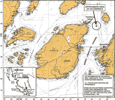
Appendix B -Diagram of the CO2 distribution manifold
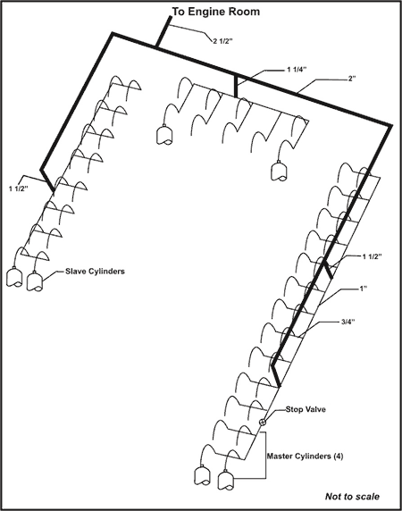
Appendix C - List of supporting reports
The following TSB Engineering Laborarory reports were completed:
- LP 042/2003 – Engine Room Fire
- LP 001/2004 – Examination of Extinguisher Pipe Fittings
These reports are available upon request from the Transportation Safety Board of Canada.
Appendix D - Glossary
- BCFC
- British Columbia Ferry Corporation (now BC Ferry Services)
- BHP
- brake horsepower
- CO2
- carbon dioxide
- CSA
- Canada Shipping Act
- defect sheet
- daily defect list
- DP
- designated person
- ECR
- engine control room
- ENC
- electronic navigation chart
- Full Away
- full sea speed ahead
- IMO
- International Maritime Organization
- ISM Code
- International Management Code for the Safe Operation of Ships and for Pollution Prevention
- kg
- kilograms
- kPa
- kilopascals
- Lloyd's
- Lloyd's Register of Shipping
- m
- metres
- Maximo
- BCFC's fleet-wide planned maintenance database
- MCTS
- Marine Communications and Traffic Services
- mm
- millimetres
- NFPA
- National Fire Protection Association (United States)
- nm
- nautical miles
- NPT
- national pipe thread
- QMS
- quality management system
- ro-ro
- roll-on/roll-off
- SMS
- Safety Management System
- SOLAS
- International Convention for the Safety of Life at Sea
- SSB
- Ship Safety Bulletin
- TC
- Transport Canada
- TP
- Transport Publication
- TSB
- Transportation Safety Board of Canada
- VHF
- very high frequency
- °
- degrees
- °C
- degrees Celsius
- ″
- inches