Grounding
Bulk carrier Canadian Leader
Off Cap à la Roche, upstream of
Deschaillons-sur-Saint-Laurent, Quebec
The Transportation Safety Board of Canada (TSB) investigated this occurrence for the purpose of advancing transportation safety. It is not the function of the Board to assign fault or determine civil or criminal liability. This report is not created for use in the context of legal, disciplinary or other proceedings. See Ownership and use of content. Masculine pronouns and position titles may be used to signify all genders to comply with the Canadian Transportation Accident Investigation and Safety Board Act (S.C. 1989, c. 3).
Summary
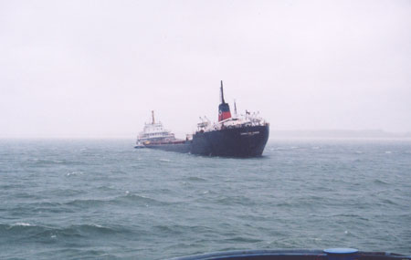
On 24 September 2005, the Canadian Leader departed Pointe-Noire, Quebec, fully loaded with iron ore pellets and bound for Hamilton, Ontario. At 0115 eastern daylight time on September 26, upstream of Deschaillons-sur-Saint-Laurent, Quebec, the vessel sustained a blackout. With the helm no longer responsive, the vessel took a sheer to starboard and ran aground near buoy D38. Water ingress was observed in the forepeak and the No. 1 starboard ballast tank. Three hours later, on a rising tide, two unsuccessful attempts to refloat were made.
Later that morning, the crew realized that the cargo hold was taking in water and, once the vessel's management company was apprised of the situation, a salvage tug and equipment were requested. Upon arrival, portable pumps were rigged and de-watering commenced. At approximately 0525 on September 28, the third attempt to refloat was successful. The vessel then proceeded to the Port of Québec, where it was partially unloaded and underwent temporary repairs. Afterward, the vessel resumed its voyage toward the Great Lakes.
1.0 Factual Information
1.1 Particulars of the Vessel
| Name | Canadian Leader ex Feux Follets |
|---|---|
| Official number | 32574 |
| IMO number | 6719330 |
| Port of registry | Toronto, Ontario |
| Flag | Canada |
| Type | Bulk carrier |
| Gross tonnage | 18 045.19 |
| LengthFootnote 1 | 217.20 m |
| DraughtFootnote 2 | Forward: 8.64 m Aft: 8.72 m |
| Built | 1967, Collingwood Shipyard, Collingwood, Ontario |
| Propulsion | General Electric steam turbines, 6714 kW, driving one fixed-pitch propeller and a bow thruster |
| Cargo | 26 242 tonnes of iron ore pellets |
| Crew | 20 |
| Registered owner(s) | Upper Lakes Shipping Ltd. |
| Ship manager | Seaway Marine Transport |
1.1.1 Description of the vessel
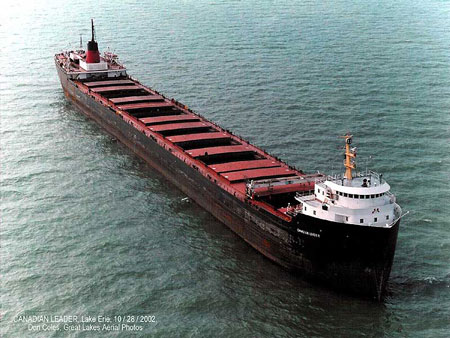
Built in 1967, the Canadian Leader is a Great Lakes bulk carrier (see Photo 1). Propulsion power is provided by steam turbines and the vessel is also fitted with a bow thruster. The engine room and the galley with their respective crew are located aft, while the wheelhouse and the deck crew are located forward. The vessel's single watertight hold is subdivided by screen bulkheads into six cargo holds and accessed by 17 hatch covers.
1.2 History of the voyage
1.2.1 Grounding
The Canadian Leader called at Wabush Mines, Pointe-Noire, Quebec, for a full load of iron ore pellets. A total of 26 242 tonnes was loaded on 24 September 2005. The vessel departed the same day bound for Hamilton, Ontario.
The following day, at about 2110 eastern daylight time,Footnote 3 the vessel arrived at the Québec pilot station for pilot relief. Following a master/pilot information exchange, the next pilot assumed conduct of the vessel in the presence of the officer of the watch (OOW) and a helmsman. The weather was overcast with scattered showers, and visibility was approximately five nautical miles (nm).
On September 26, shortly after taking over the watch, the second engineer initiated a soot-blowing operation of the two boilers, using the soot-blowing air compressor sets. While this was ongoing, he carried out the daily boiler-water test. The vessel was by then in the vicinity of Deschaillons-sur-Saint-Laurent, making way at a speed of 9.5 knots on a heading of 246.5° Gyro (G) between buoys D36 and D38 off Cap à la Roche. While the second engineer was logging the result of the water test at 0115, there was a loud bang and a sizzling sound coming from the direction of the switchboard. Immediately afterward, the vessel experienced a total blackout.
On the bridge, the pilot requested that the anchor station be crewed. Power, provided by the harbour generator, was restored after 18 seconds, but the steering gear pump unit did not start automatically, nor was this required. As the vessel began a sheer to starboard, the pilot requested emergency steering - or any other way to steer the vessel. The helmsman made several unsuccessful attempts to regain control by trying the pump switches at the steering console and switching from "follow-up" to "non-follow-up." Although slowing down, the main propulsion steam turbine continued to provide propulsion power until the steam throttle valve was closed.
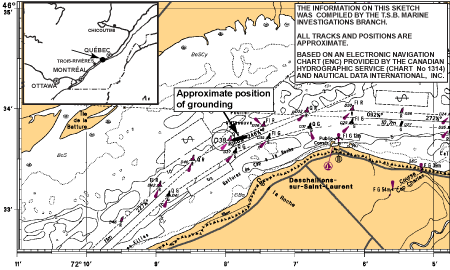
Meanwhile, the OOW phoned the master and briefed him on the situation. The master immediately came up to the bridge. The vessel continued its sheer to starboard, left the channel, and, at 0117, ran aground on the north side of the channel near buoy D38 in position 46° 33′40″ N, 072° 07′56″ W (see Figure 1). The chief engineer and the third engineer rushed to the engine room to help restore electrical and steam power to the propulsion plant. The helm was regained later but not soon enough to prevent the grounding.
Shortly after the grounding, the first mate sounded all ballast tanks, including the forepeak, and informed the master and the pilot that the forepeak and No. 1 starboard ballast tank were taking on water. During this time, electrical power was restored to the propulsion plant and the port anchor was dropped two shackles in the water.
The Canadian Leader informed the Marine Communication and Traffic Services (MCTS) centre of the blackout and grounding at 0118 and 0122 respectively.
1.2.2 Salvage
At 0130, the master, using the company hotline, informed the operations manager of Seaway Marine Transport (SMT) of the vessel's situation. The master called the MCTS centre and asked that passing vessels reduce their speed. At 0200, the vessel requested tug assistance to secure it in position. The tug Avantage subsequently departed Trois-Rivières at 0250, reaching the Canadian Leader at 0430. At 0204, the MCTS centre called Transport Canada (TC) to advise them of the situation.
In the meantime, based on tidal considerations, the bridge team agreed on a window of opportunity (around 0400) for a first refloating attempt. At 0304, the MCTS centre was advised by the pilot that an attempt to refloat would be made. The TC inspector on duty was advised of plans to refloat the vessel. The attempt involved using the ballast pumps to empty the flooded No. 1 ballast tank, in addition to the thrust of the main propulsion plant and the bow thruster, combined with the action of the wave-lifting effect from a downbound vessel. The attempt, however, was unsuccessful.
Upon the arrival of the tug Avantage, two lines were made fast between the vessel and the tug. During a second refloating attempt at 0510, one of the lines slipped off the tug's hook; the second line then parted. It was decided to cease the refloating operation. Monitoring of the soundings was ongoing and the soundings remained unchanged.
Arrangements were made to board the vessel in mid-afternoon with interested parties. These included representatives from the ship manager, SMT; the underwriters; the classification society, Lloyd's Register; and government officials from the TSB and TC.
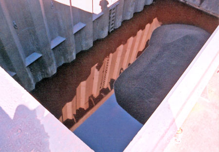
At about 0800, the vessel's list had noticeably increased. Around 1000, a crew member opened a booby hatch giving access to the cargo hold and discovered the presence of water (see Photo 3). The master immediately phoned SMT, and arrangements were made to have the salvage company, Groupe Océan, deliver portable pumps to the vessel.
In the afternoon, divers and the SMT naval architect arrived on scene. An underwater survey confirmed that the vessel was resting on the bottom from the bow to frame 181 (aft end of cargo hold No. 2) on the starboard side. Divers were unable to see any damages to the hull due to a strong tidal current that affected visibility.
The tug Ocean Delta left Québec at 1730 with salvage equipment on board, including de-watering pumps.
SMT, having previously contacted the Eastern Canada Response Corporation (ECRC)Footnote 4 and requesting that they stand by, declined the company's services at 1810. This decision was based on available information and a judgment that the risk of pollution was non-existent.
The tug Ocean Delta arrived on site at 2130. Four portable electric pumps were rigged in cargo hold No. 1, using the booby hatch access. They were used throughout the night, and the next morning, September 27, hydraulic portable pumps were lowered into cargo hold Nos. 2 and 3. This latter measure steadily lowered the water level in the cargo holds, allowing the company to study refloating options.
During the day on September 27, there was an ongoing exchange of information between SMT, TC, and the Department of Fisheries and Oceans (DFO). Salvage plans were submitted and approved by TC and the DFO. The refloating operation was scheduled for the next morning, September 28; it was to begin at approximately 0500, at high tide, and was to be carried out under the conduct of the Groupe Océan salvage master.
Arrangements were made to lower the water level in the forepeak and to use three tugs. The water level in the No. 1 cargo hold was 2.1 m. Following a meeting just before the refloating, it was decided in the presence of two pilots that the salvage master would assume command on the Canadian Leader, and that each tug would also have a pilot on board until the vessel was floating free.
At 0525 on September 28, at high tide, the vessel refloated itself. The tugs were not ready, and held the vessel in its initial position until they were ready for the escort operation. Escorted by the three tugs, the vessel then proceeded upriver to the Batiscan anchorage and subsequently turned downriver toward Section 27 of the Port of Québec. Upon its arrival at the port, TC prohibited the ship from further movement.
1.3 Injuries to persons
No injuries were reported.
1.4 Damage
As a result of the grounding, the vessel was holed in the forepeak and No. 1 starboard ballast tank, with damage to the tank top in way of the No. 1 cargo hold, allowing water ingress.
1.5 Certification
1.5.1 Vessel
The vessel held valid certificates for the type of trade and voyage in which it was engaged. Since 09 April 2002, all inspections and surveys of the vessel were delegated by TC to the classification society, Lloyd's Register.
The Safety Management Systems (SMS) for both the vessel and the ship manager were audited by Lloyd's Register and found compliant with International Safety Management (ISM) Code requirements. The Safety Management Certificate of the Canadian Leader was issued on 16 July 2002 and the SMT Document of Compliance was issued on 26 August 2004.
SMT's Quality Management System was approved by Lloyd's Register Quality Assurance as having met the International Organization for Standardization (ISO) 9001 standards and the certificate was issued on 16 December 2004.
1.5.2 Personnel
Deck officers held valid certificates of competency for the service and voyage in which the vessel was engaged, and crew members met appropriate requirements.
The chief engineer was hospitalized in Pointe-Noire before the vessel left and thus the second engineer was acting as chief engineer. He held a second-class engineer, steamship certificate, issued in 1986, and a fourth-class engineer, motor ship certificate, issued in 1992. The acting second engineer held a fourth-class engineer, combined certificate, issued in 1999, and the acting third engineer held a fourth-class engineer, combined certificate, issued in 2002. The acting chief engineer had approximately 10 years' experience on this vessel, and the acting second and third engineers had joined the vessel in the spring of 2005.
1.6 Weather and tide
At the time of the grounding, the weather was overcast with scattered showers and occasional heavy rain. Humidity was 99 per cent, winds were calm (0 to 3 knots westerly), and visibility was about 5 nm.Footnote 5
In the sector of the river off Deschaillons-sur-Saint-Laurent, the tidal amplitude is about 1.5 m. On the day of the occurrence, high tide was 2.12 m at 0330. Low tide was 0.65 m at 1200. At the time of the grounding, the tide was rising and measured 1.33 m.
1.7 Cargo hold arrangement
1.7.1 Design
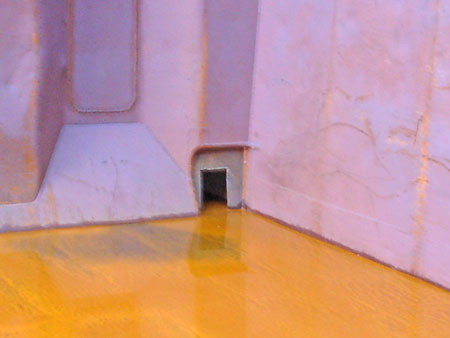
The vessel has a single watertight hold, which is subdivided into six cargo holds, each separated by a screen bulkhead. Each screen bulkhead is designed with drainage openings at the tank top level on both sides of the bulkhead (see Photo 4). Each cargo hold has a booby hatch allowing access and/or inspection from the main deck.
1.7.2 Water Detection
No sounding pipes or other means of determining the presence of water in the cargo hold were fitted, nor were they required to be.
1.8 Cargo hold pumping
1.8.1 Bilge pumping arrangement
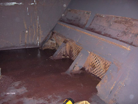
The vessel's pumping arrangement includes two bilge wells in the aft end of the single watertight cargo hold. The bilge wells are located on the port and starboard sides of the hold, adjacent to the aft bulkhead (in the aft end of cargo hold No. 6). The bilge wells are situated on the tank top, within the hopper, at the cargo hold's side and extend from the aft bulkhead to 4 m forward. The cargo hold pumping arrangement is linked to the ballast pumping system by a 455 mm pipe. Each bilge well has three strainer plates; 550 mm by 450 mm, with 25 mm perforations (see Photo 5).
The Marine Machinery RegulationsFootnote 6 state in part that
48. An efficient pumping system shall be fitted with bilge suction pipes at suitable drainage levels and located so that all water within any compartment . . . can be pumped out. . . .
51. . . . bilge suction pipes in holds . . . shall be enclosed in strainers that (a) have perforations not more than 10 mm in diameter. . . .
Furthermore, the regulations require that the ship be able to pump from both forward and aft in a single cargo hold, but that only aft end suctions are required for vessels operating in inland waters, given certain provisions. The Canadian Leader met these provisions.Footnote 7
1.8.2 Sealing of bilge well strainer plates
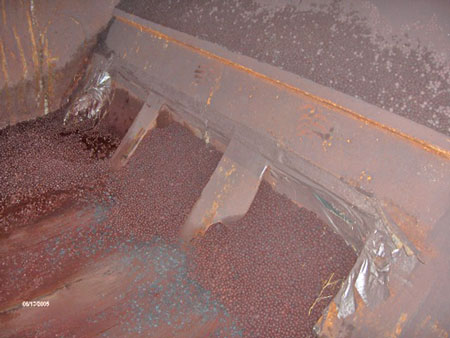
To prevent ore pellets from entering the bilge wells, the crew sealed the strainer plates using cardboard, plastic sheeting, and duct tape (see Photo 6). This was not a written procedure; however, it was common practice on board the vessel when similar cargo was carried.
Although not mandatory for the Canadian Leader, the International Maritime Organization (IMO) Code of Safe Practice for Solid Bulk Cargoes requires, inter alia, that "attention is drawn particularly to bilge wells and strainer plates, which should be specially prepared to facilitate drainage and to prevent entry of the cargo into the bilge system." Guidance is also provided in the Canadian Code of Safe Practice for Solid Bulk Cargoes (TP 5761) and the Grain Cargo Regulations. Vessels plying domestic trade are not subject to pre-loading inspections as required for foreign trade vessels. Protection of cargo hold bilge wells is therefore not verified on domestic trade vessels.
1.8.3 Safety management system - Pumping procedures
The SMS documentation revealed a discrepancy in the ballast-pumping procedure in relation to the cargo hold's equipment. Section 02 of this procedure refers to "four cargo hold suction wells," whereas the vessel is equipped with only two.
1.9 Cargo description
Standard loads of iron ore contain a mixture of different sized pellets. Granulometry testsFootnote 8 for this load show that 6.7 per cent of the pellets were less than 10 mm and that 98.9 per cent of pellets were 15.8 mm or less.
1.10 Other occurrences
There are approximately 60 Great Lakes bulk carriers. TSB statistics revealed that, from 1990 to 2005, there were 62 groundings involving this type of vessel, some of which took on water as a result.
On 14 July 1970, the bulk carrier Eastcliffe Hall made contact with the bottom in the St. Lawrence River off Morrisburg, Ontario. The vessel subsequently flooded and sank within minutes.
On 20 November 1974, the bulk carrier Roy A Jodrey struck Pullman Shoal in the St. Lawrence River. The damage was similar to that sustained by the Canadian Leader and resulted in the flooding of the cargo hold and tunnel space. The Roy A Jodrey sank some 4½ hours later.
As vessels of the same era and design (that is, with single holds) are still operating and are not being replaced on a scheduled basis, these occurrences demonstrate the potential severity of the consequences should the vessels ground or sustain flooding as a result of other accidents.
1.11 Electrical system
1.11.1 Power plant and distribution system
The main electrical power supply on board the Canadian Leader is a 600 V three-phase alternating current (AC) distribution system. The vessel has two steam turbine-driven generators of a capacity of 600 kW each and one diesel-driven harbour generator of a capacity of 250 kW feeding a single switchboard. The switchboard is composed of receiving and distributing circuit breaker panels linked together by a common horizontal bus bar system. The distribution is done via 11 separate panels, that is, breaker panels or motor control centres (MCCs). This has the benefit of isolating separate panels for maintenance and repair work.
The two MCCs, called MCC A1 and MCC A2, supply power to the engine room machinery and are connected to the main buses via bus bars. The other panels, which are not part of the main switchboard but are found throughout the ship, are for ventilation, bow thruster and steering gear equipment, winches, transformers, and deck machinery; these panels are interconnected to the main buses using wire cables.
1.11.2 Circuit breakers
The main generators, main switchboard, and MCCs are interconnected using ITEFootnote 9 circuit breakers. Circuit breakersFootnote 10 of 1600 A are used to connect the two steam turbine generators, while 600 A circuit breakersFootnote 11 are used to connect MCC A1 and MCC A2. The K600 circuit breakers fitted to feed the MCCs are fitted with electro-mechanical trip devices,Footnote 12 while the K1600 circuit breakers are fitted with solid-state trips.Footnote 13
An examination following the blackout revealed that the short-circuit indicators on both steam turbine generator circuit breakers had been activated.
TC's Ships Electrical Standards (TP 127E, 09/2007) states, "Overload and short-circuit protection shall be so arranged that effective discrimination is achieved for all essential services."Footnote 14 However, because this standard was introduced in 1976, it was not in force at the time of the Canadian Leader's construction.
1.11.3 Bus bars
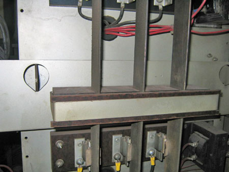
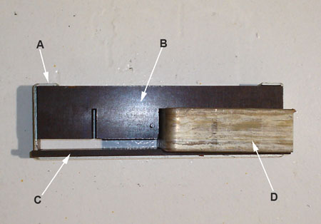
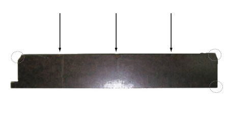
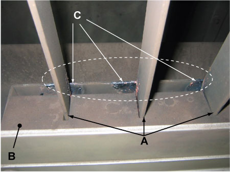
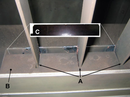
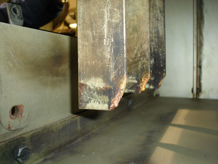
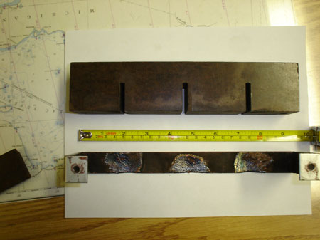
Three bus bars, supplying power to the No. 1 ballast pump, are secured to the switchboard casing with a steel bracket and, to insulate the bars, two styles of bakelite insulation pieces are used. One of the insulation pieces, installed horizontally, has three notches to keep the bars apart. The other insulation piece has an "H" shape and is a 6 mm flat piece. This "H" piece is enclosed vertically between the bus bar edges and the steel bracket, preventing the bars from sliding out of the notches and coming into contact with the steel bracket (see Photo 7 and Photo 8).
The vertically mounted 6 mm flat bakelite insulation piece was discovered later on the deck inside the switchboard casing covered with a fairly uniform layer of dust, indicating that it had fallen away sometime earlier. Also, three tabs out of four were missing and marks of indentations were visible in way of the three bus bars, indicating that the bars had had a tendency to press the bakelite insulator against the steel bracket (see Photo 9).
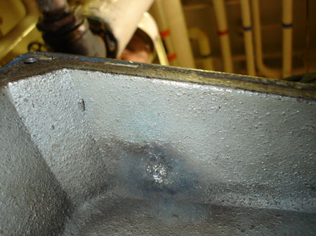
An examination revealed that arcing took place between the bus bars and the steel bracket (see Photo 10, Photo 11 and Photo 12), not directly between the bus bars.Footnote 15
According to TP 127, an air gap of at least 22 mm would be required to prevent arcing between the bus bars and the adjacent bracket; however, since the bakelite insulation piece was missing, the maximum air gap distance between bus bars and ground would have been only 6 mm.
1.11.4 Regulatory inspection of switchboard
There were no regulatory or vessel inspection requirements that would have possibly led to the discovery of the missing 6 mm insulation piece that fell from its place between the bus bars and the bracket to the deck some time before the occurrence. It was not until the breaker panel was dismantled after the accident that the piece was found, covered in dust, on the deck. The design of the switchboard was such that the missing insulation would not have been obvious to an engineer under normal operating conditions.
TP 127 covers requirements, inter alia, for initial testing and inspections on board ship. It requires a complete inspection of the electrical installation, equipment, or apparatus on initial inspection, and subsequent periodic inspections are to determine mechanical and electrical condition and performance. There are no specific requirements concerning bus insulators and supports in the periodic inspection of a vessel's switchboards other than for propulsion switchboards.
1.11.5 Aft air compressor set
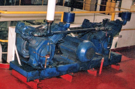
The soot-blowing operation necessitates the use of dedicated air compressors. There are two sets of soot-blowing compressors on board; each set is comprised of one electric motor driving two compressors in tandem (see Photo 14). These sets are identified on the switchboard as AIR COMPRESSOR FWD and AIR COMPRESSOR AFT. Each air compressor set is electrically supplied through a 50 A circuit breaker.
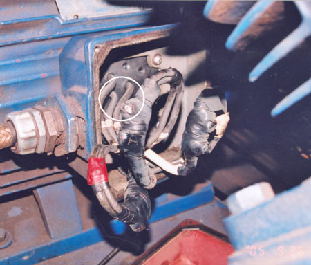
Several hours after the power was restored subsequent to the blackout, the second engineer noticed a dead phase ground fault while closing the circuit breaker connecting the aft air compressor set. One of the wires in the connection box of the electrical motor was later found to have been in contact with the inside top of the casing (see Photo 15 and Photo 16).
1.11.6 Harbour generator
The diesel-driven harbour generator is located outside the engine room and is also referred to and used as an emergency generator. An auto-start feature allows the generator to self-start and distribute power to the main switchboard for services considered to be essential in the event of a power failure, thereby replacing the steam turbine generators. In this occurrence, the diesel generator came on line approximately 18 seconds after the blackout. It should be noted that the harbour generator output is insufficient to power the bow thruster.
1.11.7 Vessel's blackout procedure
The blackout procedure to be followed by engine room personnel states in partFootnote 16
. . . If ship is underway and Emergency Generator Breaker has not closed, then manually close the breaker as it is important to feed steering gear as soon as possible.
In this occurrence, engineers concentrated on restoring propulsion requirements, and the steering gear pump was restarted later.
1.11.8 Marine Machinery Regulations
The current Marine Machinery Regulations prescribe the following:Footnote 17
16. Main and auxiliary steering gear power units shall be;
- capable of being brought into operation from a location on the bridge;
- arranged to start automatically where power is restored after a power failure; and
- equipped with an audible and visible alarm located on the bridge to indicate a power failure to any one power unit.
The Canadian Leader, built before 1990, was not required to comply with the above.
1.12 Emergency plans
1.12.1 Company plan
It is the responsibility of the ship owner or his representative to ensure an adequate response to an emergency affecting his vessel.
The company has a Marine Emergency Response Plan (MERP) to ensure that all levels of management have a "uniform approach to handling crisis situations." In it, various scenarios are considered, including grounding.
This plan stipulates sounding the tanks - though not the cargo hold specifically - to discover any water ingress in the event of a grounding. It adds, "Whenever grounding occurs, the potential for a pollution incident to occur always exists."
1.12.2 Vessel plan
At the time of the occurrence, vessel procedures for grounding or stranding included a checklist of questions. These included:
- bilges and ballast tanks sounded?, and
- assessment of cargo conditions?
1.12.3 Company proposed salvage plan
The proposed salvage plan, submitted on 27 September 2005, was comprised of the following steps:
- continuous pumping of water from the cargo hold;
- transfer pumping and pressurizing equipment on board the Canadian Leader;
- start pressurizing forepeak and No. 1 starboard ballast tank;
- meeting on board with tug master, pilot, and captain;
- making fast three tugs to Canadian Leader by 0430;
- start pulling at 0530 and slowly increase pull until 0630;
- if the vessel refloats, proceed to the Grondines anchorage and, after obtaining clearance, proceed to Québec under escort of three tugs;
- sail to Port of Québec with pumps and pressurizing equipment operating;
- if unsuccessful with refloating attempt, commence unloading operation.
1.12.4 Emergency preparedness of agencies
1.12.4.1 Transport Canada
In response to a marine occurrence, a TC inspector may board and inspect any vessel in Canadian waters and detain the vessel if the inspector deems it necessary (Canada Shipping Act (CSA), sections 310 and 377). The inspector, in the role of pollution prevention officer, also has powers to instruct and direct a vessel when a risk of pollution is evident (CSA, Section 662).
Furthermore, Schedule 3, Performance of Salvage Operations, of the Canada Shipping Act, 2001, Chapter II, Article 9, states that
Nothing in this Convention [International Convention on Salvage] shall affect the right of the coastal State . . . to take measures . . . to protect its coastline . . . from . . . the threat of pollution following . . . a maritime casualty . . . which may reasonably be expected to result in major harmful consequences, including the right . . . to give directions in relation to salvage operations.
1.12.4.2 Department of Fisheries and Oceans
In response to a marine occurrence, the DFO will coordinate its resources with other agencies as required with respect to search and rescue activities (CSA, Section 385), control and direction of marine traffic (CSA, Section 562.18), and pollution response activities.
It is the DFO's position that the ship is first responsible to respond in a pollution occurrence. In cases where the polluter is unknown, unable, or unwilling, the DFO may assume the lead for the response. Part XVI of the CSA gives the Minister (of Fisheries and Oceans) certain powers with respect to pollution or possible pollution occurrences, which include the following:
678(1) Where the Minister of Fisheries and Oceans believes . . . that a ship . . . is likely to discharge a pollutant, the Minister may
- take such measures . . . to prevent pollution damage from that ship, including the removal or destruction of the ship. .
- monitor the measures taken . . . to prevent pollution . . . or
- direct any person to take measures to prevent pollution . . . or prohibit any person from taking such measures. . . .
The DFO has produced a standard notice to owners that requires an owner to submit intentions with respect to corrective actions or preventive measures to be taken to prevent a pollution threat, and a salvage plan. A deadline for such a submission is also stated.
In Canada, the framework supporting marine emergencies has evolved over the last few years, a change that was triggered by the grounding of the Alcor in 1999.Footnote 18 The subsequent TSB report described shortcomings including an inadequate initial response and an improvised first refloating attempt. This report noted the bridge team's working relationship as being fragmented and uncoordinated, and pointed out that essential parties were not involved in the planning and development of the salvage operation, resulting in a poorly coordinated salvage that later also caused the near collision of the tanker Eternity with the container vessel Canmar Pride.
The Board subsequently recommended that
The Department of Transport, the Department of Fisheries and Oceans, and Canadian pilotage authorities, in consultation with marine interests, develop, implement, and exercise contingency plans to ensure that risks associated with navigation-related emergencies are adequately addressed.
Transportation Safety Recommendation M03-03 (issued January 2004))
The TSB investigation into the grounding of the bulk carrier Yong KangFootnote 19 near Québec, Quebec, in 2003 resulted in the Board issuing a Safety Concern stating, in part
. . . navigational risks . . . may still persist until a comprehensive assessment of such risks is undertaken and the corresponding emergency response measures are put in place.
The Quebec TC Marine Safety Directorate and Quebec DFO Marine Programs Directorate prepared a documented framework relating to marine emergencies. It includes the following:
- Guide de gestion des événements maritimes exceptionnels, April 2005, CCG/TC, Quebec Region
- Système de gestion des interventions - Guide de l'utilisateur, May 2004, DFO-CCG; and
- Marine Safety Response Guide, 2003, TC Quebec Region - Marine Safety (see Appendix B)Footnote 20
Produced subsequent to Recommendation M03-03, the first document is a joint guide on the management of unusual marine occurrences in the Quebec region. It outlines the roles and responsibilities of each department where coordinated efforts are required, and includes procedures for assessing risk situations. An exercise to test the coordinated alerting and communication capabilities has been carried out. This system, finalized in January 2007, is in place in the Quebec region, and if the methodology is expanded to the entire country, it would substantially reduce the risks associated with navigation-related emergencies. The recommendation response was therefore assessed as "Satisfactory in Part" by the Board.
The second document is a workbook to help DFO personnel monitor and respond to pollution incidents. The system is based on the Incident Command System (ICS) and includes generic worksheets for risk identification, on-site safety, assigned tasks and responsibilities, inter-agency communication, environmental/wildlife impact, human resources, and material.
The third document is a TC guide for marine emergencies in the Quebec region. It lists the powers, objectives, safety activities, necessary information, and action to be taken by TC staff. The document's grounding scenario includes the following:
- request additional information if needed for decision making;
- prohibit vessel from moving until refloating plan has been accepted (if necessary); and
- accept refloating plan.
1.12.5 Submission/approval of the salvage plan
Salvage information was submitted independently to both the DFO and TC.
Information required pursuant to the issued notice had to be submitted to the DFO by 1700 on September 26, and the DFO advised SMT at 1342 of the issues that should be addressed. On September 27 at 1405, SMT advised the authorities that Groupe Océan would carry out the salvage operation and, at 1734, a salvage plan was submitted to the DFO. This plan was rejected due to a lack of stability information. At 1810, authorities were given more information on tug positioning and vessel stability, and at 1843, TC sent the revised salvage plan to the DFO with the following conditions:
- the salvage master was to take charge of all manoeuvres by the ship and tugs;
- once the vessel was refloated and had entered the channel, the salvage master was to pass over the conduct of the vessel to the pilot.
The DFO agreed with these conditions and returned the approved plan to SMT, subject to noted questions and comments (see Appendix A).
2.0 Analysis
2.1 Cause of the blackout
2.1.1 Short circuit
An arc occurs between two conducting electrodes separated by a gap filled with a gas such as air. In this occurrence, one of the electrodes was the bus bar and the other was the steel bracket. When a suitable voltage is supplied, a spark forms, ionizing the gas and drastically reducing its electrical resistance. This is normally prevented by inserting an insulation piece.
The H-shaped piece of bakelite from the insulation arrangement that rests against the steel bracket between the three bus bars was missing at the time of the blackout. This piece had fallen out of place some time before the occurrence. This insulation piece, which is approximately 6 mm thick, showed signs of indentation where the bars rested, indicating that the bars had a tendency to move toward the bracket as the breaker mated with the bus bars. Given the absence of the insulation piece, the spacing (gap) between the edge of bus bars and the bracket would have been less than 6 mm on each such occasion.
The reduced gap would increase the possibility of an arc occurring, and this was a factor in the arcing of the bus bars, but it was not likely the initiating factor, since the reduced gap had been present for some time.Footnote 21
The humidity in the switchboard area is normally quite high and there was high humidity at the time of the occurrence. However, as humidity increases, there are fewer free ions in the air, and thus there is a decrease in the ability of an electron to move across an air gap, meaning that an arc will be less likely.
Furthermore, since the ship was carrying iron ore, the ore dust could have settled on various parts. This dust was likely partially conductive, which would have increased the probability of arcing. However, this was not likely the initiating factor because the vessel had previously loaded iron ore without arcing occurring.
The marking inside the connection box of the aft air compressor (see Photo 16) was fresh, indicating that a single contact followed by repulsion may have created a build-up of electrical potential within the ship's structure in way of the switchboard steel bracket. This condition appeared new at the time of the occurrence.
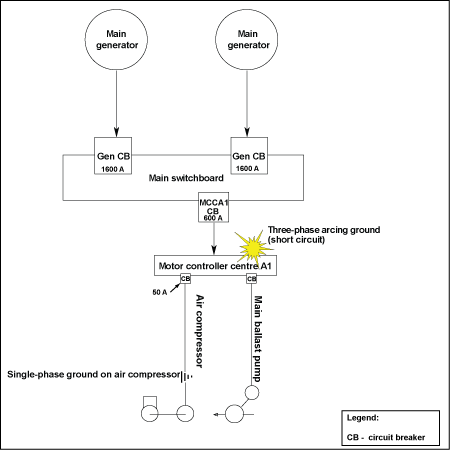
The air compressor circuit breaker is meant to instantly protect from phase-to-phase shorts, as opposed to single phase-to-ground shorts; thus, although the breaker would open on a short to ground, it would take much longer. The single contact could have created a potential (voltage) spike on the main buses, thereby increasing the potential across the air gap between the edge of the bus bars and the steel bracket. This led to an instantaneous three-phase arcing short circuit that occurred on the No. 1 ballast pump supply bus bars, located downstream of MCC A1.
The missing insulator was one of the necessary conditions that contributed to causing the blackout. Because the insulator had been missing for some time without any adverse consequence, it would not likely have been the only condition. Many conditions were present, increasing the possibility of an arc occurring; however, the addition of the short to ground on the air compressor line likely added the extra potential needed for the bus bars to arc the way they did in this occurrence.
2.1.2 Coordination of electrical protective devices
The fault in the air compressor likely triggered an arc short circuit on the No. 1 ballast pump bus bar. The upstream MCC A1 breaker tripped. However, both generator circuit breakers also tripped simultaneously as a result of this short circuit, indicating inadequate breaker coordination. The resulting blackout left the vessel without steering.
The 1976 edition of TP 127, section 17(2), required overload and short-circuit protection to be arranged so that effective discrimination is achieved as far as practicable throughout the installation. The 1987 edition of TP 127 introduced the requirement to submit to TC, for new vessels, a "Coordination Study of Main and Emergency Distribution Systems."
This ensures that essential services further upstream are not disrupted allowing the rest of the power system to remain in service.
2.2 Steering gear
When navigating in any restricted waters, steering is vital and must be regained as soon as possible after a blackout. Engine room personnel, however, often focus on restoring the main propulsion plant in such circumstances, and as such the steering gear pump may not be made available in a timely manner. In this occurrence, engineers concentrated on restoring propulsion requirements, and the steering gear pump was restarted later. Even if the vessel's blackout procedure had been followed exactly, the phrase "feed steering gear" could be misinterpreted because it does not specifically say "start" steering gear (that is, electrical power may have been restored to the steering gear, but the electrically powered motor of the steering gear pump may not have been restarted).
Although electrical power was regained within 18 seconds following the blackout, the vessel's steerage capability was not automatically restored. Given that the vessel had headway with reducing propulsion, the vessel continued to sheer until grounding.
The 1980 edition of TP 127 Section 11(15) states that: "The control of each steering gear motor is to be such that the motor will restart automatically upon restoration of voltage after a power failure." Other Canadian vessels built before 1980 may have arrangements similar to the Canadian Leader; that is, their steering gear does not immediately restart, putting them at risk of a loss of steering following a blackout.
2.3 Awareness of water in the cargo hold
Timely detection of water ingress into a loaded bulk carrier's cargo hold is vital for many reasons, especially when aground. Such information influences the decisions as to whether refloating attempts or other salvage options should be considered.
In this occurrence, the Canadian Leader was not equipped with water-level detection equipment for the hold, be it sounding pipes or water-level alarms. Consequently, vessel personnel were unaware of the water ingress until the booby hatch to the forward hold was opened some 10 hours after the grounding. By that time, the single cargo hold had progressively flooded aft past non-watertight cargo screen bulkheads.
In 2002, the IMO adopted a number of amendments to the International Convention for the Safety of Life at Sea (SOLAS), 1974. One new regulation requires each cargo hold on a bulk carrier - regardless of the vessel's construction date - to be fitted with water-level detectors.Footnote 22 SOLAS requirements do not apply to Canadian inland waters bulk carriers such as the Canadian Leader. The Canada Shipping Act, 2001 regulatory reform, currently underway, will introduce a proposal for similar requirements regarding water-level detectors in cargo holds as found in SOLAS.
Vessels not fitted with means to detect water in the cargo hold are at risk in the event of water ingress.
2.4 Cargo hold pumping
A vessel must be able to efficiently pump water from any compartment, including the cargo hold, under normal conditions of trim and heel. Vessels that are unable to pump out water from their holds are at risk in the event of water ingress. Regulations recognize the need to be able to pump from both forward and aft in a single cargo hold; however, the Canadian Leader, exempt from such requirements, was fitted with only aft bilge wells. When the vessel developed a trim by the head after grounding, water located in the forward part of the cargo hold could not be pumped out.
The effectiveness of a bilge pumping arrangement depends on the extent of damage to the vessel's cargo hold, and how the system might be affected by the cargo and/or the material covering the strainer plates.
To prevent the iron ore pellets from entering the bilge wells, the strainer plate perforations were sealed off using, among other material, plastic sheeting that rendered the bilge pumping arrangement ineffective. This is a common practice on Great Lakes bulk carriers. Compromising the ability to pump water from the cargo hold could impair the vessel's stability to a point where it could contribute to a more serious occurrence.
2.5 Emergency response plans
In the event of a marine emergency concerning a vessel in a restricted waterway such as the St. Lawrence River, emergency preparedness concerns not only the personnel on board the vessel, but that of the vessel's company staff and the relevant governmental authorities. TC is responsible for "the safe operation, navigation, design and maintenance of ships, the protection of life and property, and prevention of ship source pollution."Footnote 23 The Department of Fisheries and Oceans (DFO) is responsible for safe and accessible waterways, healthy and productive aquatic ecosystems, and sustainable fisheries and aquaculture.Footnote 24 The management of events after an emergency is a complex operation, and decisions must be made in a timely manner. This analysis will focus on the emergency preparedness of all parties in order to highlight any residual risks.
2.5.1 Marine Emergency Response Plan - Company
SMT manages a fleet of ships, and the company's Marine Emergency Response Plan (MERP) is the template for dealing with emergencies. Although this plan states that compartments are to be sounded subsequent to grounding, the plan does not specifically mention the need to monitor cargo holds for water ingress. In a single-cargo-hold vessel, it is paramount to be aware of any water entering the hold, and, in this instance, the discovery of water in the hold changed the salvage situation dramatically.
As both of the hold's bilge wells were located aft and had been sealed before loading the cargo, the vessel could not use its ballast pumps to cope with the water ingress in the cargo hold. The shipboard SMS procedures for pumping made reference to four bilge suctions - two in the centre of the cargo hold (port and starboard) and two in the aft end of the cargo hold. As such, the vessel's SMS documentation with respect to bilge pumping arrangements was not ship-specific.
The company's plan reads as follows: ". . . Whenever grounding occurs, the potential for a pollution incident . . . always exists." Based on information at hand that indicated no damage to fuel tanks and therefore no threat of pollution, at 1810, SMT declined the services of the Eastern Canada Response Corporation (ECRC).
The vessel was capable of pumping water from the No. 1 starboard ballast tank. It did not have the capability to pump water directly from the cargo hold and therefore it was in a potentially dangerous situation. Portable salvage pumps were ordered and arrived at 2130.
2.5.2 Marine Emergency Response Plan - Vessel
Soon after the grounding, the crew sounded the compartments and took soundings around the vessel's perimeter to evaluate the situation. An initial attempt to free the vessel was made around 0400, and a second one soon after the tug Avantage arrived. That attempt ended at 0510 when one towline slipped off a hook and the other broke. Had either of the attempts been successful, without the knowledge of the hold flooding, there was a risk that the vessel may have later sunk in the channel.
Emergency preparedness plans cannot predict every contingency. They can, however, set out directives and procedures for complex, pressure-filled scenarios where there is little margin for error. A checklist of questions alone is a poor substitute for a proper vessel emergency plan.
- Bilges and ballast tanks sounded?
- Engines and steering secured?
- List and trim noted?
- Assessment of cargo conditions?
- Assessment of any pollution or potential pollution?
- Overall conditions assessed in terms of risks of safety to crew, vessel, and cargo?
These statements provide no direct guidance should water ingress be found. They provide no schedule to continue sounding. They provide no method or guidance to ascertain if water is entering the cargo spaces. Furthermore, they do not offer guidance on pulling with tugs, the safe working load of bollards, or other precautions. The IMO has, for example, documented the failure of mooring equipment under heavy load, and has noted its concern in the past.Footnote 25
Shipboard emergency response plans should be read and initialled by officers and, if possible, practised to ensure familiarity. They should also be made available to crew members such that all hands have a good understanding of requirements given certain circumstances.
In the case of a grounded vessel, all risks must be assessed before any self-refloating attempt, and appropriate measures must be put in place to mitigate those risks. Otherwise, adverse consequences can occur.
In this instance, the Canadian Leader's emergency plan - although inadequate by nature of its incomplete question-checklist format - was not even followed. Water in the hold was only discovered by chance some 10 hours after the grounding, whereas the use of a more comprehensive emergency response plan could have made an earlier discovery possible.
2.5.3 Proposed salvage plan
The proposed salvage plan was sent to government authorities at 1734 on 27 September 2005; TC raised several concerns and the DFO also asked for some additional information to be clarified. The plan was accepted later that evening despite lacking essential details, such as:
- predicted tides and currents;
- calculations of the forces exerted by the current on the hull;
- expected weather;
- mooring bitt strength assessment;
- exact nature of sea bottom;
- estimated force and location of ground reaction; and
- estimated force needed to free the vessel and available bollard pull.
2.5.4 Governmental authorities
TC and the DFO have responsibilities that include the safety of persons, the vessel, the waterway, and the environment. They must, therefore, develop, implement, and exercise contingency plans to ensure that risks associated with navigation-related emergencies are adequately addressed. The CSA provides the legislative basis for TC and the DFO to take the necessary action to prevent the possibility of pollution. Furthermore, the DFO states in a notice to owners that, if the desired information - in this case the salvage plan - is not submitted before a specified time, the department will have no choice but to initiate appropriate corrective actions to remedy the situation for, and in the name of, the ship owner.
Informed decisions and appropriate corrective actions for marine emergencies can only be achieved if serious, in-depth pre-planning has been done. Although vessel owners are responsible for the salvage of their vessels, government authorities must nonetheless assess the timeliness/appropriateness of the emergency response and, if necessary, give directions or take charge. This can only be achieved if substantial contingency planning is done ahead of time to develop ready-made emergency plans.
The response to TSB Recommendation M03-03 was assessed as Satisfactory in Part. This, in addition to the Safety Concern that followed the Yong Kang investigation and the investigation into the Horizon grounding,Footnote 26 indicates that there continue to be inadequacies in the preparedness and coordination of emergency response.
In this instance, had either of the first two refloating attempts been successful - both of which were made outside the scope of an approved salvage/refloating plan and carried out with no format approval - measures were not in place to deal with the potential risks.
Canadian authorities continue to operate without the benefit of comprehensive contingency plans when confronted with marine emergencies such as groundings.
3.0 Findings
3.1 Findings as to causes and contributing factors
- A ground fault in the aft air compressor, which likely created a potential (voltage) build-up (spike) between the main buses and the bracket, combined with the missing bakelite insulator and the reduced air gap between the edge of the bus bars and the steel bracket, caused arcing to take place.
- When arcing started in one phase, it spread to the other two phases, causing a short circuit downstream of the motor control centre A1 (MCC A1) bus bar.
- Inadequate breaker coordination caused MCC A1 and the two main generator circuit breakers to open, causing a blackout.
- The blackout deprived the vessel of helm control, which was not immediately restored when electrical power was regained, resulting in the vessel grounding.
3.2 Findings as to risk
- An inadequately coordinated tripping sequence failed to immediately isolate an affected section of the switchboard, thereby increasing the risk of creating a blackout.
- Other Canadian vessels may have arrangements similar to the Canadian Leader whereby their steering gear does not automatically restart, potentially prolonging the duration of a loss of steering following a blackout.
- Vessels not fitted with means to detect water or that are unable to pump water out of their holds are at risk in the event of water ingress.
- The strainer plates were sealed off, rendering the cargo hold bilge pumping arrangement ineffective.
- The company's Marine Emergency Response Plan (MERP) states that compartments are to be sounded subsequent to grounding, but it does not specifically mention the need to monitor cargo holds for water ingress, which increases the risk that water ingress may go undetected.
- The vessel's MERP - itself inadequate by nature of its incomplete question-checklist format - was not followed, and risks were not assessed.
- Either of the first two refloating attempts, made outside the scope of an approved salvage/refloating plan and carried out with no formal approval, could have resulted in a more serious occurrence had they been successful.
- Canadian authorities continue to operate without the benefit of comprehensive contingency plans when confronted with marine emergencies such as groundings.
- There are no specific requirements concerning bus insulators and supports in the periodic inspection of a vessel's switchboards.
3.3 Other findings
- The cargo hold bilge well strainer plates had holes of 25 mm in diameter, rather than the maximum of 10 mm.
- The vessel's Safety Management System documentation with respect to cargo hold bilge pumping arrangements was not ship-specific.
4.0 Safety action
4.1 Action taken
4.1.1 Coordination of electrical protection devices and switchboards
On 04 April 2006, the TSB issued Marine Safety Information Letter (MSI) 03/06 to the ship manager, Seaway Marine Transport (SMT) with a copy sent to Transport Canada (TC). This letter expressed concern that, after the two main generators and motor control centre A1 (MCC A1) circuit breakers had been sent ashore for testing, no coordination test was conducted after their re-installation and that, as a consequence, the tripping sequence relationship between those breakers remained unknown and could present a risk to the vessel.
TC responded that only new installations are required (under Section 36 of the Ships Electrical Standards (TP 127)) to submit, among others, a "Coordination Study of Main and Emergency Distribution Systems" for evaluation. There is no regulatory requirement for a test following the replacement or recalibration of equipment. TC also stated that it is not recommended to conduct a test to prove the coordination of protective devices due to the possible destructive/dangerous consequences of such a test.
SMT informed the TSB that electrical inspection procedures for switchboards and feeder breakers have been enhanced to include testing in conjunction with the main generator breakers every five years. SMT has since issued Circular Letter 77-2005 to all chief engineers; infrared scans are now performed yearly fleet-wide as a preventative action and regular inspections and cleaning to detect and correct any switchboard defects have also been put in place. The company will consider upgrading the MCC's breaker protection with electronic trips, similar to those on the main breakers if tests indicate a potential problem.
Similarly designed switchboards and breakers on other SMT ships were identified. During the winter layup period of 2006, a detailed inspection of the insulation was carried out to identify any defects for correction. None were found and these identified ships are now on a similar inspection program as the Canadian Leader.
4.1.1.1 Steering gear
Following this occurrence, SMT made modifications to the Canadian Leader's steering gear, making one pump start automatically once power is restored after a blackout. Similar ships in the SMT fleet were surveyed and retrofitted as necessary with either a wheelhouse-fitted steering pump start switch and/or a one-pump automatic start mechanism to coincide with power restoration following a blackout. This was completed during the winter layup of 2006.
4.1.2 Water detection and bilge pumping arrangement
On 28 February 2006, the TSB issued Marine Safety Advisory (MSA) 02/06 to TC, with a copy sent to SMT. This MSA indicated several practices that may not be limited to the vessel or ship manager, including the lack of means to detect water in a single cargo hold, the use of strainer plates with holes larger than 10 mm, and the sealing off of the cargo hold bilge wells when carrying permeable cargoes.
On 15 November 2006, TC updated an earlier response, stating that the size of the holes in the strainer plates was not relevant in this occurrence and that covering the strainer plates with plastic ensures that bilge and ballast arrangements are free of debris. Furthermore, in relation to water ingress detection, TC states that, due to the rarity of a ruptured tank top, the present system of detection is considered adequate for existing vessels.
A further update on 16 March 2007 advises that TC has conferred with vessel operators to investigate practices highlighted in the advisory. However, there is no indication of any changes made. Furthermore, it has been considered that it is not appropriate to publish a Ship Safety Bulletin, but that further consultation with vessel operators is required with respect to the issue of strainer plate holes and coverings.
SMT's Marine Emergency Response Plans (MERPs) have been amended to reflect the need for assessing cargo hold conditions (breaching of ballast tanks) during grounding with respect to salvage plans.
4.1.3 Safety management system - Procedures
On 06 December 2005, SMT modified its procedures, which reflect a correction that made the number of bilge wells vessel-specific. In particular, the sentence referring to "four wells" was amended to read "two wells."
4.1.4 Emergency preparedness
On 20 June 2006, SMT stated in a letter to the TSB that the effectiveness of the company's MERP was reviewed using the response to the Canadian Leader accident. More specific details have since been added to the various emergency response sections, so as to provide improved guidance in the management of an occurrence. A further review has taken place as recently as November 2007, and the 2008 revision will reflect these changes and improvements.
4.2 Safety concerns
4.2.1 Adequacy of emergency preparedness
When responding to an occurrence, specific issues often emerge that dominate the response effort and affect the outcome. Following such an occurrence, it is prudent for the authorities to re-examine their preparedness, planning, and response activities in order to take appropriate and timely measures to address these issues. An example of this has been the United Kingdom government's approach to removing or reducing the risk to persons or property during occurrences involving vessels. In response to recommendations following the grounding of the oil tanker Sea Empress in 1996, a new role was created for a single representative, the Secretary of State's Representative (SOSREP), to oversee and to exercise ultimate command and control in maritime salvage and intervention operations. In January 2007, the containership MSC Napoli sustained serious damage to its hull and was abandoned. While under tow to a safe haven, its condition deteriorated seriously enough that the SOSREP ordered that the vessel be intentionally grounded in a specific location to minimize the prospect of pollution and to facilitate anticipated salvage operations.
The need for a planned and coordinated approach to deal with navigation-related emergencies in Canadian waters, while supporting the vessel owner's efforts to deal with an occurrence, was recognized by the Board in its investigation into the 1999 grounding of the bulk carrier Alcor.Footnote 27 As a result of that investigation, the Board recommended that:
The Department of Transport, the Department of Fisheries and Oceans, and Canadian pilotage authorities, in consultation with marine interests, develop, implement, and exercise contingency plans to ensure that risks associated with navigation-related emergencies are adequately addressed.
Transportation Safety Recommendation M03-03 (issued January 2004)
In response, both Quebec regional directorates - Department of Fisheries and Oceans (DFO) Marine Programs and TC Marine Safety - identified the respective departmental roles where coordinated efforts are required. Together, they developed procedures to assess risk situations and carried out an alerting exercise in 2006. However, this action was a regional effort that did not address all the issues required for an effective, timely response. Furthermore, there is no information to suggest that such a nationwide plan is being implemented.
Given Canada's extensive coastline, its intricate waterway system, and the large number of vessels constantly in service throughout the country, the probability of a serious marine accident taking place cannot be discounted. For example, an average of 95 groundings and/or strikings involving commercial vessels occurs in Canadian waters each year.Footnote 28 The Board, meanwhile, has continued to identify contingency planning deficiencies as a key factor in a number of occurrences.Footnote 29
Following the grounding of the vessel Horizon in 2004, the DFO indicated that area-specific risk assessments and contingency plans could not be undertaken due to a lack of available human and financial resources. The Board, however, believes that this work is crucial to establishing effective and timely risk-based decision-making procedures to protect persons, property and the environment in the event of groundings. In the occurrence involving the Canadian Leader, the response to the grounding did not adequately address the risks involved. There were no comprehensive contingency plans in place, and the first two refloating attempts were made without the benefit of a comprehensive salvage/refloating plan.
The Board acknowledges the actions taken by TC and the DFO to date specifically in developing re-floating plans in the event of grounding. However, the Board believes that more tangible, nationwide action involving marine interest groups and agencies is necessary. Since Recommendation M03-03 was issued more than four years ago, a coordinated nationwide approach has yet to be realized. The Board is concerned that the slow progress toward developing, implementing, and exercising marine contingency plans results in a continuing risk to vessels, crew members, and the environment.
4.2.2 Detection of water ingress
When the Canadian Leader grounded, the No. 1 starboard ballast tank was extensively damaged, and the tank top was ruptured. As a consequence, once the ballast tank flooded to the level of the cargo hold, water began entering the cargo hold.
The Canadian Leader was not equipped with water-level detection equipment in the hold, be it a sounding pipe or water-level detector. Consequently, the crew was unaware of the presence of the water ingress until the booby hatch to the forward hold was opened some 10 hours after grounding. By that time, the single cargo hold had progressively flooded aft past non-watertight transverse cargo screen bulkheads. To prevent the iron ore pellets from entering the bilge wells, the strainer plate perforations had been previously sealed off using, among other material, plastic sheeting that rendered the pumping arrangement to the cargo hold unusable. This practice is presently used to a large extent on Great Lakes bulk carriers.
Timely detection of water ingress into a loaded bulk carrier's cargo hold is vital. Such information will influence the emergency measures undertaken when a vessel has sustained damage causing water ingress in the cargo hold. In 2002, the International Maritime Organization (IMO) adopted a number of amendments to the International Convention for the Safety of Life at Sea (SOLAS), 1974. One new regulation requires each cargo hold on a bulk carrier - regardless of the vessel's construction date - to be fitted with a water-level detector.
Currently, such requirements do not apply to Canadian inland waters bulk carriers such as the Canadian Leader. The Canada Shipping Act, 2001 regulatory reform, currently underway, will introduce a proposal for similar requirements regarding water-level detectors in cargo holds as found in SOLAS. Furthermore, SMT's MERPs have been amended to reflect the need for assessing cargo hold conditions (breaching of ballast tanks) during grounding with respect to salvage plans. However, such a visual inspection of the cargo hold for water would not detect early flooding in the event that the vessel was carrying cargo, and, as in this occurrence, the water would not be visible until it reaches the top of the cargo.
If water is entering the vessel, either from sources above or below the waterline, a vessel must be able to efficiently pump water from any compartment, including the cargo hold, under normal conditions of trim and heel. Although the permeability of some cargoes precludes effective pumping, permeable cargoes such as the iron ore pellets carried by the Canadian Leader do allow sufficient water flow-through.
The practice of sealing cargo hold strainer plates on Great Lakes bulk carriers is at odds with Safety Convention bulk carrier practice. The IMO Code of Safe Practice for Solid Bulk Cargoes requires, inter alia, that "attention is drawn particularly to bilge wells and strainer plates, which should be specially prepared to facilitate drainage and to prevent entry of the cargo into the bilge system."Footnote 30 Guidance is also provided in the Canadian Code of Safe Practice for Solid Bulk Cargoes (TP 5761) and the Grain Cargo Regulations.
Vessels plying domestic trade are not subject to pre-loading inspections as required for foreign trade vessels. Protection of cargo hold bilge wells is therefore not verified on domestic trade vessels.
The Board is therefore concerned that Great Lakes bulk carriers and their crews, which continue to operate without the benefit of water-detection systems in cargo holds, and continue the practice of sealing off cargo hold bilge wells, may be at undue risk in the event of the ingress of water into the cargo hold.
The Board will continue to monitor any action taken in relation to the above concern.
This report concludes the Transportation Safety Board's investigation into this occurrence. Consequently, the Board authorized the release of this report on .
5.0 Appendices
Appendix A - Department of Fisheries and Oceans (DFO) questions and comments
DFO Response to the Salvage Plan of the Canadian Leader
- Who will be the master in charge of directing the tugs?
- Who will be the master in charge of the salvage operation?
- From where will the master in charge of the salvage operation direct the tugs?
- Proper communication system has to be used.
- What will be the role of the Canadian Leader's captain during the operation?
- Require the bridge to be manned according to good practices of bridge management.
- When will the pilot take charge of the vessel, and in which position relative to the channel?
- Each towing point on board the Canadian Leader should be crewed with direct communication with the towing master.
- The safe working load and the type of line should be sufficient according to the bollard pull of the tug.
- The towing point on the Canadian Leader should be reinforced if necessary.
- The head tug should have a safety line in case the main one breaks.
- The towing master to advise DFO on the possible obstruction of traffic, four hours prior to any operation.
- Port authority at destination to be advised, and port section to be given.
- If any pollution - or the threat of any pollution - occurs during the salvage or in transit, all action must be taken to stop and/or contain the loss of oil. In addition, all measures must be taken to protect the environment and the safety of life at sea.
- If any pollution - or the threat of any pollution - occurs at the port, all action must be taken to stop and/or contain the loss of oil. In addition, all measures must be taken to protect the environment and the safety of life at sea.
Appendix B - Excerpts from Transport Canada Quebec Region - <em>Marine Safety Response Guide</em>
Guideline #6 - Grounding
Mandate
Authority
Objectives
Required Information
Marine Safety Activities
Special Instruction
Other Parties
References
Mandate
Safety of life at sea
Protection of the environment
Authority
- Canada Shipping Act, Part V
- s 310: inspect, ask questions, detain
- s 377: report (Canadian ships only)
- Canada Shipping Act, Part XV
- s 662 (1) b): go on board (Canadian ship)
- s 662 (1) c): go on board (foreign ship)
- s 662 (1) e): take samples
- s 662 (1) f): direct
- s 662 (1) i): collect information on SOPEP (Shipboard Oil Pollution Emergency Plan)
- Canada Shipping Act, Part VI,
- s 478: report accidents and occurrences
- Arctic Waters Pollution Prevention Act,
- s 15 (4) a): board
- s 15 (4) b): order
Objectives
- Take measures to protect human life, the environment, property, and cargo.
- Check vessel for seaworthiness in accordance with Canadian legislation as well as applicable rules and conventions.
- Determine the causes of the grounding and recommend measures to prevent a repetition, and/or investigate possible violations of the CSA with a view to prosecution.
- Inform minister if necessary.
Required information
- Particulars of vessel: see form
- Vessel's conditions: damage, potential risks for navigation, risk of pollution
- Environmental conditions: weather, tide, currents
- In case of risk of pollution, information on implementation of emergency plan (SOPEP)
- Causes of incident
- Vessel's intentions
Marine safety activities
- Obtain information from Alert and Warning Network (AWN)
- Request additional information if needed for decision-making
- Prohibit vessel from moving until refloating plan has been accepted (if necessary)
- 1.3 - Mechanical problems
- 1.4 - Ships (light draft) proceeding in ice
- 1.5 - Ships directed to obtain services of tug
- 1.6 - Drifting ships to remain at a certain distance from the coast
- Decide whether an inspector must be sent to site immediately.
If yes:
- Make travel arrangements for an inspector (see transportation)
- Ensure inspector's working conditions will be safe
- Send inspector immediately to assess vessel condition and investigate
- Coordinate inspector's activities and provide support
- Validate decisions throughout the process if necessary
- Report regularly to AWN
- Liaise with CCG (re: pollution, protection of navigable waters)
- Request report from shipboard inspector in order to obtain supplementary information
- Assess damage and make decisions about refloating (interaction with shipping agent, CCG, and other organizations involved)
- Accept refloating plan
- Report to Director General if necessary; information note
- See "After refloating" below
If not, reasons:
- Vessel refloated by itself
- Combination of factors: causes are not related to vessel safety, environmental features are known (nature of bottom, tides, etc), no risk of pollution or leakage
After refloating:
- Check vessel condition, reliability of machinery, and auxiliary systems
- Direct vessel and/or accept its destination if necessary
- Issue detaining order once the vessel has arrived at its destination
- Recommend internal inspection by inspector, Classification Society, and others concerned, and recommend external inspection by divers to assess damage
- Evaluate the damage and follow up temporary repairs, permanent repairs, dry-dock work, and conditions of class
- Obtain hazardous incident report from the captain
- Report to the Director General
- When finished, lift the detaining order, close the file, and if necessary pass on information to other parties
Special instructions
Other parties
- See AWN grid
- Classification society
- Shipping agents
- Administration
References
Échouement du navire Alcor, Questions juridiques (Note de service MPO 24/11/2000) (Grounding of Vessel Alcor, Legal Issues (Memorandum DFO 24/11/2000))
Appendix C - List of laboratory reports
The following TSB Engineering Laboratory report was prepared:
- LP 018/2006 - Bus Bar Examination, Bulk Carrier Canadian Leader
This report is available from the Transportation Safety Board of Canada upon request.
Appendix D - Glossary
- A
- ampere
- AWN
- Alert and Warning Network
- CB
- circuit breaker
- CCG
- Canadian Coast Guard
- CSA
- Canada Shipping Act
- DFO
- Department of Fisheries and Oceans
- ECRC
- Eastern Canada Response Corporation
- G
- Gyro (degrees)
- Gen
- generator
- ICS
- Incident Command System
- IMO
- International Maritime Organization
- ISM
- International Safety Management
- ISO
- International Organization for Standardization
- ITE
- inverse time element
- kW
- kilowatt
- m
- metre
- MCC
- motor control centre
- MCTS
- Marine Communication and Traffic Services
- MERP
- Marine Emergency Response Plan
- mm
- millimetre
- N
- north
- OOW
- officer of the watch
- SMS
- Safety Management System
- SMT
- Seaway Marine Transport
- SOLAS
- International Convention for the Safety of Life at Sea
- SOPEP
- Shipboard Oil Pollution Emergency Plan
- SOSREP
- Secretary of State's Representative
- TC
- Transport Canada
- TP
- Transport publication
- TP 127E
- Ships Electrical Standards
- TSB
- Transportation Safety Board of Canada
- W
- west
- °
- degree
- ′
- minute
- ″
- second
