Capsizing
Fireboat 08-448B
Halifax Harbour, Nova Scotia
The Transportation Safety Board of Canada (TSB) investigated this occurrence for the purpose of advancing transportation safety. It is not the function of the Board to assign fault or determine civil or criminal liability. This report is not created for use in the context of legal, disciplinary or other proceedings. See Ownership and use of content. Masculine pronouns and position titles may be used to signify all genders to comply with the Canadian Transportation Accident Investigation and Safety Board Act (S.C. 1989, c. 3).
Summary
On the morning of 17 September 2008 at approximately 1045 Atlantic daylight time, the Fireboat 08-448B capsized during training and familiarization exercises in Halifax Harbour, Nova Scotia. All eight persons on board were recovered from the water by a Canadian Coast Guard rescue boat.
Factual information
Particulars of the vessel
| Name | Fireboat 08-448B |
|---|---|
| Hull identification number | MSV02328H809 |
| Port of registry | not availableFootnote 1 |
| Flag | not availableFootnote 1 |
| Type | small vessel (fireboat) |
| Gross tonnageFootnote 2 | 2.21 (not assigned)Footnote 3 |
| Approximate dry weight | 4024 kg |
| Length | 7.58 m (outside of the hull) |
| Built | 2008, Harbor Guard Boats, Costa Mesa, California |
| Propulsion | Two 250 BHP (186 kW) Mercury Verado outboard engines |
| Persons on board | 8 |
| Owner | Harbor Guard Boats, Costa Mesa, California |
Description of the vessel
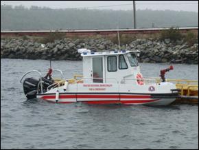
The vessel was designed as a fireboat of composite fibreglass construction with a moulded, progressive deep V-hull, fitted with a pilot house with seating for four inside and for two outside on the after deck. Access to the pilot house is through two sliding doors, port and starboard. The hull below the main deck is subdivided by two non-watertight bulkheads separating the forward hold, the gas tank, and the inboard engine compartment. The lower deck is accessed through four watertight hatches. Two side platform dive doors are fitted in the port and starboard bulwarks.
All functions of the vessel, with the exception of the aft fire monitor, are controlled from inside the pilot house. The vessel is fitted with three gasoline engines: a pair of 250 horsepower (HP) outboards and a 315 HP inboard. The outboards are used for manoeuvring. The inboard can power the two fire monitors or the jet drive.
According to the tender document, the vessel was to be capable of operating "in 33 knot winds with 3 m waves, and ice up to one inch thick." It was to be constructed in accordance with applicable Canadian regulations.
History of the voyage
During the week of 15 September 2008, firefighters from the Halifax Regional Municipality's Fire and Emergency Services, Nova Scotia, were undergoing a series of half-day training and familiarization exercises on the fireboat they were soon to take over. Four such exercises were carried out on September 15 and 16. On September 17 at 0930,Footnote 4 four firefighters, a deputy fire chief, and a student assembled at the Dartmouth Canadian Coast Guard (CCG) base, where the vessel was berthed, and met with the vessel's manufacturing representative (serving as an instructor) and the local sales representative. Before departure, the instructor explained the vessel's equipment and systems. The firefighters asked if they were exceeding the load capacity of the vessel and were told that the capacity was not an issue.
At about 1000, the vessel departed its berth and proceeded into Halifax Harbour, where the instructor carried out a series of manoeuvres and demonstrated the vessel's capabilities, including operation of the fire pump and monitors. Following this, one of the firefighters took the controls to practise replicating the manoeuvres and operating the fire pump/monitors. The vessel proceeded toward the CCG base to drop off the deputy chief.
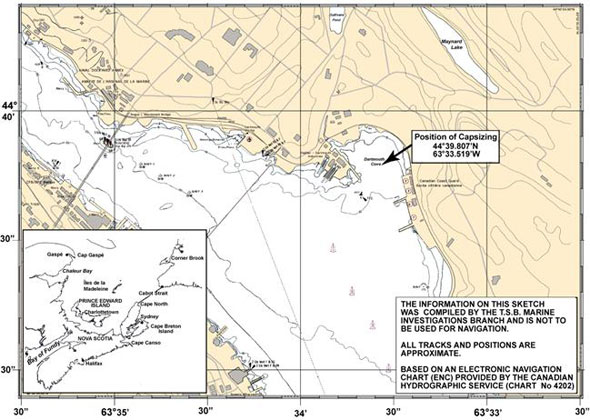
Because the firefighter at the controls had never docked the vessel before, a series of practice runs were initiated alongside a small buoy in Dartmouth Cove (see Appendix A). Following several runs, the firefighter moved the vessel ahead, put the wheel over to port, and slowly increased both throttles. After completing an estimated 90 degrees of a 180-degree turn, the vessel began to heel to port. The operator immediately pulled back on both throttles, but was instructed by the instructor to increase throttle. He complied, but the vessel continued to heel over, and before it had completed a 180-degree turn, the vessel rolled over and capsized.
Three crew members immediately surfaced, followed by the other five persons, who had been briefly trapped in the pilot house. A CCG officer on board the CCG cutter Sambro, which was docked nearby, noticed the capsized vessel and notified Halifax Marine Communications and Traffic Services (MCTS). The officer then took charge of a fast-rescue craft tied up at the CCG base and, with the assistance of several shore-based personnel, recovered all eight people from the water.
Damage to the vessel
The vessel, which was subsequently recovered, sustained extensive damage to the three engines, the control systems, and electronics. There was no apparent damage to the hull or superstructure.
Environmental damage
PollutionFootnote 5 from the capsizing was quickly dissipated through evaporation and wind/wave action. Impact to the environment was negligible.
Injuries to persons
All eight persons on board were transported to the CCG base for treatment. Injuries included water ingestion, mild hypothermia, and minor cuts and abrasions. None of the injuries were life threatening.
Vessel inspection and certification
The Fireboat 08-448B, which was in the process of being inspected by Transport Canada (TC),Footnote 6 had not received final certification for operation in Canada. At the time of the occurrence, a stability assessment had not been carried out on the vessel.
As a small vessel not exceeding 15 in gross tonnage, it was subject to the current Small Vessel Regulations, to the Construction Standards for Small Vessels (TP 1332)Footnote 7 and to the stability requirements of standard ISO 12217-1Footnote 8 of the International Standardization Organization (ISO), together with other applicable regulations.Footnote 9 Halifax Regional Municipality's Fire and Emergency Services, in consultation with TC, decided that the vessel would be assessed against design category C.
Such a vessel is designed for waves of up to 2 m (significant height) and a typical steady wind force of six on the Beaufort scale. These conditions may be encountered on exposed inland waters, in estuaries, and in coastal waters in moderate weather conditions. Winds are assumed to gust to 17 m/s (33 knots). The tender document specified that this vessel was to operate in 3 m seas.
Canadian regulations require a vessel of this size and type to comply with stability standards, but the data are not required to be submitted to TC for approval.
Personnel certification and experience
The firefighter at the controls of the vessel held a valid Pleasure Craft Operator Certificate, as required. The certificate was issued in 2003.
He had over 20 years of experience operating vessels including small pleasure boats, patrol boats, and rescue craft.
Weather conditions
The weather was sunny and clear. Winds were variable at five knots with calm seas; the air temperature was 18°C.
Lifesaving equipment
All crew members on board the vessel were wearing personal floatation devices (PFDs).
Post-occurrence observations
The investigation revealed the following:
- The engine kill switch had not been secured to the operator (via a "dead man's lanyard").
- The port and starboard outboard throttle settings were set at three-quarters ahead.
- Both outboard motors were in the amidships position.
- The inboard engine compartment hatch had not been closed and secured.
- The starboard pilot house door had been installed upside down.
- The average mass of the firefighters on board the vessel at the time of the occurrence was 94.5 kg .
- The bilge pump overboard, which was installed very close to the waterline, was not fitted with a non-return valve.
- The starboard engine appeared to be engaged ahead, although, because of the damage, this could not be verified.
- The port engine was disengaged.
Engine compartment bilges
Before departure on the morning of the occurrence, the bilges were checked and found to be dry. The bilge pump and high bilge level alarm had both been tested earlier. It is not known if the bilge pump was running. The high bilge level alarm was not heard. Although it is possible that water could have backflowed to the bilges through the overboard discharge, the location of both the bilge pump and high bilge alarm would allow only 5 cm of water to accumulate before activating. As the vessel was inherently trimmed by the stern, it was estimated that this 5 cm of water would equate to a volume of about 0.03 m³ . Calculations indicate that this would have had a negligible effect on the stability of the vessel.
Emergency egress
At the time of the occurrence, three of the crew members were on the stern, four were in the pilot house, and one stood in the open port door. When the vessel capsized, the three crew members on the stern swam clear of the vessel. Shortly thereafter, the crew member who had been standing in the doorway surfaced.Footnote 10 Those inside the pilot house quickly became disoriented as the buoyancy in their PFDs pinned them to the deck overhead. Attempts to open the closed starboard door were not successful, and one person discarded his PFD in order to escape. The remaining three eventually surfaced after exiting through the port door.
Pilot house doors
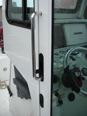
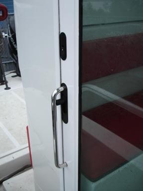
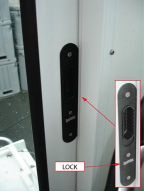
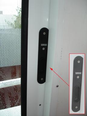
The two pilot house doors could be opened from the outside. They could also be opened from the inside via a flush-mounted door latch. To operate the latch, a user was required to place one or more fingers in a slot measuring 19 mm by 55 mm and push down (see photo 4 and photo 5). The starboard door, however, had been installed upside down; its latch therefore worked in the opposite direction—to open it, the user had to apply pressure upward. In addition, the lock for each door was adjacent to the finger slot. The lock switch was a left/right toggle requiring little effort to manipulate.Footnote 11 Once the lock switch was engaged, there was no sign or other visible indication that the door was locked.
During the pre-departure orientation session, crew members were not instructed on the use of the door latch system nor notified that the starboard door had been installed upside down.
Operator's manual
The operator's manual was not specific to this particular vessel. Rather, it was a manual produced for an earlier vessel with a different layout, equipment, and instrument/helm configuration. Although the manual contained information common to both vessels, many items specific to the Fireboat 08-448B were not addressed. An excerpt reads, in part:
The boat has been designed to safely carry the driver and up to six other persons, if the total carried weight does not exceed the maximum load capacity (see SPECIFICATIONS, page 2). Never exceed the load capacity.
The manual, however, contained no specifications as to the load capacity.
Stability
TSB post-occurrence activities
No accurate specifications or plans were supplied for the Fireboat 08-448B. A computerized model was produced and an inclining experiment was carried out to establish the vessel's lightship characteristics. Various conditions of loading were prepared and used to simulate vessel stability at the time of the occurrence.Footnote 12 Stability was then assessed against international and Canadian standards set out in two respective documents: ISO 12217-1 and the Stability, Subdivision, and Load Line Standards (TP 7301).Footnote 13
Furthermore, given the engine power available and the fact that the vessel was manoeuvring at the time of the occurrence, the vessel's stability was also assessed in order to compare the heeling moment created by the engine thrust against the vessel's righting moment.
ISO 12217-1
ISO 12217-1 sets out four possible design categories based on expected operating environments:
| Design category | A | B | C | D |
|---|---|---|---|---|
| Wave heightFootnote 14 (up to) | Approx. 7 m | 4 m | 2 m | 0.5 m max. |
| Typical Beaufort wind force | Up to 10 | Up to 8 | Up to 6 | Up to 4 |
| Calculation wind speedFootnote 15 ( m/s ) | 28 | 21 | 17 | 13 |
To be assigned any of these four design categories, a vessel's stability is assessed against a maximum of eight different tests/requirements:
- downflooding openings
- downflooding height
- downflooding angle
- offset load test
- resistance to waves and wind
- resistance to waves
- heel due to wind action
- floatation
These tests, except the ones for the resistance to waves and wind, the resistance to waves, and the offset load test, provide an indication of the vessel's resistance to taking on water. The tests for the resistance to waves and wind and the test for the resistance to waves, which provide an indication of the stability reserve based on the area under the righting lever curve, are applicable only to design categories A and B. The offset load test provides an indication of vessel stability at loaded displacement against offset distribution of the crew. The assessment of vessel stability in accordance with ISO standards is based on an average mass of 75 kg per person.
Small commercial vessel fleet
A previous TSB investigationFootnote 16 noted that there are approximately 50 000 small commercial vessels operating in Canada.Footnote 17 As of April 2009, TC indicated that 32 353 of these had been licensed or registered (gross tonnage of 15 or less).
The number of small vessels assessed to the ISO 12217-1 standard is not available. Although section 5.2.1 of the Construction Standards for Small Vessels (TP 1332) requires that "All power driven vessels shall meet the requirements of ISO 12217-1," there is no obligation to have the stability assessment submitted for approval.
History of stability requirements for small vessels
Over the years, TC has made progress toward a comprehensive regulatory framework for small vessels.
In 1974, TC published a version of Construction Standards for Small Vessels (TP 1332) that did not contain stability provisions and was to be used only for guidance. In 1975, TC published Stability, Subdivision, and Load Line Standards (TP 7301). This document, which is based on international recommendations on stability criteria developed by the International Maritime Organization (IMO), contains a series of stability standards for various types of vessels including, for example, Stab 4 (for Fishing Vessels), Stab 5 (for passenger vessels carrying more than 12 passengers), and Stab 6 (for non-passenger vessels and passenger vessels carrying not more than 12 passengers).
Between 1978 and 1995, there were numerous modifications to the Small Vessel Regulations; none of these, however, made stability requirements mandatory. In 1995, therefore, TC began discussions with various marine stakeholders aimed at implementing an acceptable mandatory standard.
In the late 1990s, changes to the Canada Shipping Act led to new inspection requirements for many small vessels and, in 1999, TC established an interim programFootnote 18 aimed at moving small passenger vessels toward compliance with regulation requirements. In 2001, TC compared the ISO stability standards to those of the United States Code of Federal Regulations and the United Kingdom's Code for Small Vessels. Although the ISO requirements were generally found to be less stringent, a number of benefits were identified with adopting the ISO standards, including:
- the Canadian maritime industry would move toward harmonization with international standards;
- flexibility would be allowed by matching design/construction characteristics with operational environments;
- the industry request for a national standard providing minimum level of safety would be met; and
- a majority of small vessels would need only minor modifications to become compliant.Footnote 19
In April 2005, the stability and buoyancy standards of ISO 12217-1 were adopted in their entirety and made mandatory for new vessels built on or after 01 April 2005. The standards for existing small vessels remained voluntary and less specific,Footnote 20 despite the later publication of Ship Safety Bulletin (SSB) 07/2006, which provided various options against which stability could be assessed.Footnote 21
Analysis
Stability
Assessment According to ISO 12217-1 – Crew of Four
The assessment calculations first assumed a crew of four (the standard complement for a typical fire station) as identified in Table 2, and then with a crew of six (the number of seats on board) as identified in Table 3, as a fully decked vessel.
| Design categories | A | B | C | D | |
|---|---|---|---|---|---|
| Criteria | Actual values | ||||
| Downflooding openings | Not less than 0.2 m (or otherwise compliant with ISO 9093) | Not less than 0.2 m (or otherwise compliant with ISO 9093) | 0.03 m for discharge bilge pump and not compliant with ISO 9093 | ||
Minimum downflooding height using Annex A (m) or using Figures 2 and 3Footnote 22 (m) |
0.5 0.5 |
0.4 0.446 |
0.4 0.446 |
0.4 0.379 |
0.442 0.442 |
| Minimum downflooding angle (degrees) | 31.2 | 25 | 20 | 6.2 | 28.6 |
| Maximum offset load angle (degrees) | 17.4 | 17.4 | 6.2 | ||
| Resistance to waves and wind (Newton-metres-degrees) | A2 > A1Footnote 23 | A2 > A1 | n/a | n/a | A1 > A2 |
Resistance to waves, where angle of maximum righting moment < 30 degrees, maximum righting moment not less than (kN-m), and maximum righting lever not less than (m) |
750 / ØGZ max. = 29.41 6 / ØGZ max. = 0.24 |
210 / Ø GZ max. = 8.24 6 / ØGZ max. = 0.24 |
n/a | n/a | 5.78 0.13 |
| Heel due to wind action | n/a | n/a | n/a | ||
Note: Items in bold represent ISO 12217-1 standards that were not met.
As initially constructed, the vessel did not meet any of the possible design categories because the height of the through-hull fitting to the bilge pumpFootnote 24 was too near the waterline. However, as this opening could easily be modified (for instance, by the addition of a non-return valve), it was discounted and the assessment proceeded with the consideration of other possible downflooding openings located in the inboard face of the moulded bulwark.Footnote 25 These included the engine compartment vents aft and forward, and the bilge blower vent. The height of the bilge blower vent was 0.442 m and was therefore exempt from having to comply with ISO 9093.Footnote 26
The following results were found:
-
Downflooding Height
Two methods could be used: a normative method from Annex A of ISO 12217-1, or formulae based on boat length (see figures 2 and 3 of ISO 12217-1). Compliance with either one of these tests provides compliance with the test requirement. In the first case, with the vessel in minimum operating condition, the height of the bilge blower vent satisfied the requirements for design categories B, C, and D. Using the second method, the vessel satisfied only design category D.
As a result, the vessel met design categories B, C, and D for the downflooding height.
-
Downflooding Angle
The vessel was assessed in the minimum operating condition. The angle of downflooding for the bilge blower vent was 28.6 degrees. As such, it complied with the requirements for design categories B, C, and D.
-
Offset Load Angle
The vessel was assessed in the loaded displacement condition against offset loading by the crew, and the heel angle corresponding to the maximum heeling moment was 6.2 degrees. The angle of downflooding for the bilge blower vent was 26.2 degrees, which exceeded the requirement of 17.4 degrees for all design categories.
-
Resistance to Waves and Wind
This was assessed only in the minimum operating condition, and the curve of righting moment was established up to the angle of downflooding for the bilge blower vent (28.6 degrees). The righting moment and the wind heeling moment curves were plotted on the same graph and the areas between these were compared. For design categories A and B, area A2 had to exceed area A1. In this case, for design category B, the values of A2 and A1 were about 44 826 Newton-metres-degrees and 107 776 Newton-metres-degrees, respectively. For design category A, the difference was even greater. This aspect of the vessel, therefore, did not meet this requirement for design categories A and B.
For design categories C and D, this test was not applicable.
-
Resistance to Waves
The maximum righting moment is 5.78 kN-m, which does not meet the requirement for design categories A and B. In addition, the righting lever at 30 degrees was 0.13 m , which does not meet the minimum requirement of 0.24 m .
For design categories C and D, this test was not applicable.
-
Heel Due to Wave Action
The windage area of the hull and the deckhouse, compared to the length and breadth of the hull, was such that this test was not required for this vessel.
As tested—with a crew of four—the vessel met the criteria for design categories C and D. As such, the operating environment would consist of significant wave height of up to 2 m and a typical steady wind force of six or less on the Beaufort scale. These conditions would typically be encountered on exposed inland water, in estuaries, and in coastal waters in moderate weather conditions. Winds are assumed to gust to 17 m/s (33 knots).
The vessel, however, was tendered to operate in seas of up to 3 m and, potentially, could have been assessed against design category B.
Following this, calculations were repeated—this time for a crew of six persons (the number of seats aboard). Vessel stability was assessed against all of the same tests/requirements, with the exception that the downflooding angle and the resistance to waves and wind were assessed in both the minimum operating condition and in the loaded displacement condition. This was due to the ratio between the loaded displacement mass and the mass of the vessel in the minimum operating condition being greater than 1.15.
In this second set of calculations, the mass of the crew, the maximum total load, and the loaded displacement mass were 450 kg , 820 kg , and 4844 kg , respectively.
Assessment according to ISO 12217-1 — Crew of six
| Design Categories | A | B | C | D | |
|---|---|---|---|---|---|
| Criteria | Actual Values | ||||
| Downflooding openings | Not less than 0.2 m |
Not less than 0.2 m |
0.01 m for discharge bilge pump and not compliant with ISO 9093 | ||
Minimum downflooding height using Annex A (m) or using Figures 2 and 3 (m) |
0.5 0.5 |
0.4 0.446 |
0.4 0.446 |
0.4 0.379 |
0.426 0.426 |
| Minimum downflooding angle (degrees) | 34.3 | 25 | 20 | 9.3 | 25.0 |
| Maximum offset load angle (degrees) | 17.4 | 17.4 | 9.2 | ||
Resistance to waves and wind |
A2 > A1Footnote 27 | A2 > A1 | n/a | n/a | A1 > A2 |
Resistance to waves, where angle of maximum righting moment < 30 degrees, |
750 / ØGZ max. = 33.0 6 / ØGZ max. = 0.26 |
210 / ØGZ max. = 9.25 6 / ØGZ max. = 0.26 |
n/a | n/a | 5.23 0.11 |
| Heel due to wind action | n/a | n/a | n/a | ||
Note: Items in bold represent ISO 12217-1 standards that were not met.
With a crew of six, the vessel's stability meets the tests/requirements for design categories C and D.
Although the displacement of the vessel with six persons on board and that at the time of the occurrence were the sameFootnote 28—and within the overall parameters set by ISO 12217-1—the load distribution of eight persons on deck resulted in a reduction of the vessel's stability.
Assessment according to the stability, subdivision, and load line standards (TP 7301) — Various crews and conditions
Vessel stability was also assessed against the criteria found in Stab 6Footnote 29for the following conditions:
- No. 2: Maximum load as per ISO 14946 (fuel 98 per cent), crew of four, and no waves
- No. 4: Maximum load as per ISO 14946 (fuel 98 per cent), crew of six, and no waves
- No. 6: At the time of the occurrence, crew of eight firefighters, fuel 25 per cent, and no waves
- No. 7: At the time of the occurrence, crew of eight firefighters, fuel 25 per cent, and waves of 0.5 mFootnote 30,Footnote 31
- No. 8: Maximum load as per ISO 14946 (fuel 98 per cent), crew of four, and wavesFootnote 32
| Actual values from conditions | ||||||
|---|---|---|---|---|---|---|
| Minimum requirements |
No. 2 | No. 4 | No. 6 | No. 7 | No. 8 | |
| Metacentric height (GM) upright (m) | 0.15 | 0.42 | 0.37 | 0.29 | 0.30 | 0.42 |
| Righting arm at 30 degrees (m) | 0.2 | 0.12 | 0.1 | 0.03 | 0 | 0.03 |
| Absolute angle at maximum righting arm (degrees) | 25 | 23.6 | 22.7 | 20.4 | 0 | 31.8 |
| Area from 0 to 30 degrees or flood (m-degrees) | 3.15 | 2.19 | 1.83 | 1.03 | 0 | 0.11 |
| Area from 30 to 40 degrees or flood (m-degrees) | 1.72 | 0 | 0 | 0 | 0 | 0 |
| Area from 0 to 40 degrees or flood (m-degrees) | 5.15 | 2.19 | 1.83 | 1.03 | 0 | 0.19 |
Note: Items in bold are not compliant with Stab 6 standards.
The corresponding results for conditions Nos. 2 and 4, with a crew of four and six, respectively, show that the vessel's reserve stability would decrease with the loading and that the area under the righting lever (GZ) curve (between 0 and 30 degrees) would represent 70 per cent and 58 per cent, respectively, of the corresponding Stab 6 requirement.
In condition No. 6, the through-hull fitting to the bilge pump was submerged. Moreover, although the vessel's limit of positive stability was 38 degrees, the angle of downflooding for the bilge blower vent was 24 degrees. Other than the minimum metacentric height, none of the criteria of Stab 6 were met. Therefore, at the time of the occurrence and according to this calculation, the vessel had very limited reserve stability.Footnote 33
In condition No. 7, the vessel would heel in beam waves, flood, and then capsize before regaining equilibrium.
In condition No. 8, with waves on the starboard beam, although sea conditions alone would not be enough to capsize the vessel, the area under the GZ curve (between 0 and 30 degrees) would be only 4 per cent of the corresponding Stab 6 requirement. As such, the vessel would roll severely and its marginal stability would put it in a vulnerable condition.
Loading condition Nos. 2 and 4 are based on an average mass of 75 kg per person, while loading condition Nos. 6, 7, and 8 are based on the average mass of the firefighters on board the vessel at the time of the occurrence, which was 94.5 kg .
In summary, the stability calculations for the vessel at the time of the occurrence (condition No. 6) compared to the ISO standard (condition No. 4) show that, although the displacements were the same, there was a reduction in overall stability. A comparison of the righting arm curves for the two load conditions indicates that there was a 21 per cent reduction in the metacentric height and about a 44 per cent reduction in the area under the righting arm curve.
Assessment while under power
Following the assessments against the criteria from both ISO 12217-1 and the Stability, Subdivision, and Load Line Standards (TP 7301), and given the available engine power and the fact that the vessel was manoeuvring at the time of the occurrence, a third assessment of the vessel's stability—while it was under power—was carried out. This third assessment took into consideration the location of the propellers and the attachment of the engines to the transom, in addition to the speed of the vessel just before capsizing, the turning angle, and the thrust used while manoeuvring. (Note that, as the investigation was unable to determine the turning angle, calculations were generated for a variety of angles between 10 and 22 degrees.Footnote 34)
Assuming that each outboard engine was capable of producing 250 HP (186 kW), calculations show that 71 per cent of the maximum power would be sufficient to overcome the vessel's righting moment at a turning angle of 10 degrees. This would drop to just 48 and 33 per cent of maximum power for turning angles of 15 and 22 degrees, respectively.
In addition, the minimum power required for the engines to create a heeling moment sufficient to overcome the maximum righting moment would be 178 HP , 120 HP , and 83 HP (per engine), assuming that the engines were forming an angle of 10, 15, and 22 degrees, respectively, with the centreline of the vessel. This meant that the two outboards possessed sufficient combined thrust to capsize the vessel.
Therefore, although it might be sufficient under normal circumstances to assess vessel stability using current standards, for vessels with significant engine power, consideration should be given to the effect of this power on vessel stability while manoeuvring.
Adequacy of international standardization organization standards
Regulations and standards are expected to provide a satisfactory and reliable level of safety. According to the Canada Shipping Act, the safe operation of a vessel is the responsibility of its owner/operator and, to this end, Fireboat 08-448B was undergoing the inspection and certification process so as to comply with all applicable rules and regulations. It was the future owner's expectation that, upon completion of this process, the vessel would be stable and safe to operate within the given environmental conditions/parameters.
TC defines stability as "the measure of [a vessel's] ability to withstand high winds, waves, and other forces resulting from its operations (lifting, trawling, towing, etc.) and resist capsizing by returning to an upright position after being heeled over."Footnote 35 However, there exists a discrepancy between the thoroughness of this definition and the corresponding requirements for vessels as set out in TC 's Small Vessel Regulations, which, as of 01 April 2005, set ISO 12217-1 as the only applicable standard for new vessels.
For example, although vessels in design categories A and B are assessed according to an indication of their stability characteristicsFootnote 36 in various expected operating conditions, those in design categories C and D—including the Fireboat 08-448B—are not. Instead, the "basic concept" used for vessels in design categories C and D is a vessel's "resistance to taking on water."Footnote 37 This, though, is less an assessment of stability than one of watertight integrity, and such an assessment does not provide more indicative stability criteria as found, for instance, in the more conventional standards of Stab 6. In this occurrence, the vessel capsized in conditions considerably less rigorous than those listed in category C (or even in category D).
A vessel's expected operating conditions, therefore, are only one of the many factors that can affect stability. The Construction Standards for Small Vessels (TP 1332) acknowledges this, noting that "multihulls, inflatable craft, vessels carrying cargo over 1000 kg , and vessels built or converted for towing, dredging, or lifting" are excluded.Footnote 38 Emergency response vessels in particular require significant powering, thrust, and manoeuvrability, and will often include auxiliary features such as fire monitors, side platform dive doors, towing bitts, and rescue hoists. Each of these features may have a significant impact on intact stability, which the ISO 12217-1 standard does not address. The Construction Standards for Small Vessels (TP 1332) makes no mention of engine thrust. Neither the TSB nor TC is aware of any stability standard that considers the engine thrust as a factor to be taken into consideration when evaluating static stability (with the exception of some criteria for towing based on the bollard pull).
Moreover, Stab 6 can still be applied for small vessels constructed before 01 April 2005 (and offers a greater indicator of stability and overall safety). This creates a situation whereby older vessels can be assessed against a comprehensive standard in lieu of ISO 12217-1, but newer vessels cannot.
Therefore, assessing the stability of small vessels against ISO standards contained in the Construction Standards for Small Vessels (TP 1332) alone may be insufficient.
Validity of standard weight
Current ISO standards are based on an average mass of 75 kg per person. Statistics, however, show that the average mass of Canadian males 20 years of age and over is 81.5 kg .Footnote 39 These figures are similar in the United States. In this occurrence, the average mass of the eight persons on board the vessel was 94.5 kg .
The TSB has addressed this issue previously in the marine and air modes. Following the 2003 fire and sinking of the small fishing vessel Silent Provider, the Board cited a "strong probability" that the margin of safety provided by the 75 kg standard could be inadequate.Footnote 40 Subsequent to the fatal crash of Georgian Express Flight 126Footnote 41 in January 2004, the Board recommended a re-evaluation of the standard weights for passengers and carry-on baggage, adding that these be "adjusted for all aircraft to reflect current realities."Footnote 42
The stability of small vessels has been shown to be sensitive to the weight and distribution of people on board; however, this key parameter used to evaluate the stability of small vessels continues to be based on a less-than-average value. As a result, vessels continue to be assessed against unrealistic operating conditions.
Engine kill switch
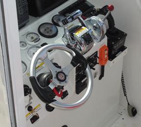
The engine kill switch (also known as the "dead man's lanyard") was not attached to the operator (see Photo 6). The purpose of such a lanyard is to stop the engines if the operator leaves the controls. Although the lanyard had been used during the training sessions earlier in the week, because the seas were calm on the morning of the accident, it was not used. Moreover, although in this occurrence both engines stopped immediately upon capsizing, not using this safety device could lead to a situation where engines continue to run with no operator.
Outboard motor position and throttle setting
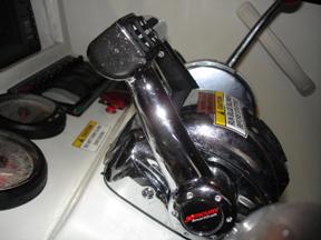
When the vessel began to heel to port, the instructor told the operator to increase throttle. This may explain why the three-quarter throttle setting (see Photo 7) and the amidships motor position conflict with reports that the vessel was in the midst of a slow, relatively tight turn at the time of the capsizing. It is also possible that the throttles were inadvertently pushed forward as the vessel decelerated while capsizing. The clutches were electrically controlled, and the investigation concluded that the port engine disengaged during the capsizing.
Engine compartment hatch
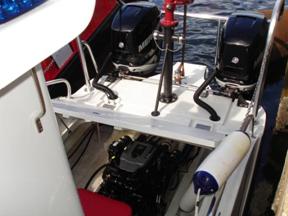
Upon recovery of the vessel, the inboard engine compartment, which had been closed but not properly secured (see Photo 8), was observed to be open. Such a practice can compromise the watertight integrity of the hull as water is shipped on board during heavy weather or aggressive manoeuvring.
Pilot house doors
Following the capsizing, crew members within the pilot house found it difficult to locate the door latch and open the starboard door. Whether this was due to the upside-down installation, difficulty in locating the relatively tiny finger slot, a lack of familiarity with its use, or because the door had been inadvertently locked is impossible to ascertain.
All crew members eventually managed to exit the pilot house (albeit with difficulty). Under different circumstances—for example, had the port door been closed—their escape could have been further delayed or even prevented.
Operator's manual
The operator's manual supplied with the fireboat was incomplete and did not provide important vessel-specific information with respect to the vessel's load capacity. The manual stated that the vessel could safely carry seven persons, provided the load capacity was not exceeded; however, at the time of the occurrence, there were eight persons on board.
Without knowing the load capacity, there was no way for the operator to determine whether the boat was safe to operate.
Findings
Findings as to causes and contributing factors
- In its departure condition, the vessel had limited reserve stability due to its load distribution on deck.
- The vessel capsized when the engine thrust created a heeling moment sufficient to overcome the vessel's righting moment during a slow turn to port.
Findings as to risk
- The stability standards of International Standardization Organization's ISO 12217-1, Small Craft—Stability and Buoyancy Assessment and Categorization, and the Construction Standards for Small Vessels (TP 1332) lack some risk factors that may have an impact on small vessel stability. Small vessels that are assessed solely against these standards may meet the criteria yet have insufficient stability.
- ISO standards that do not reflect a realistic average mass per person allow vessels to be assessed against unrealistic operating conditions.
- Without sufficient vessel-specific information in an operator's manual, a user may load a vessel beyond the maximum recommended load.
- A bilge pump overboard discharge mounted very close to the waterline and not fitted with a non-return valve can allow downflooding.
- Unsecured compartment hatches can compromise the watertight integrity of the hull as water is shipped on board during heavy weather or aggressive manoeuvring.
- Engine kill switches not used in conjunction with a "dead man's lanyard" allow engines to continue running with no operator.
- Differing door installations combined with easily engaged locks and the difficulty in manipulating door latches, or a lack of familiarity with their use, could delay or prevent emergency exit.
Safety action
Action taken
On 20 March 2009, after learning that the City of Winnipeg, Manitoba, may be operating a vessel similar to the Fireboat 08-448B, the TSB issued Marine Safety Advisory 01/09. This safety advisory summarizes the details of the occurrence and notes that the combination of the fireboat's limited inherent stability and the use of engine thrust during a tight turn may have been a factor in the capsizing. The safety advisory also states that the Winnipeg Fire and Paramedic Service may wish to have its own vessel's stability assessed to ensure that it is safe.
Transport Canada has proposed new Small Vessel Regulations and published them in the Canada Gazette, Part I, on 25 April 2009. The proposed regulations require that the stability of a small commercial vessel built on or after 01 April 2005 be adequate to safely carry out its intended operations and that the owner demonstrate this adequate stability upon request. Transport Canada is now reviewing comments from stakeholders and interested parties. Final approval and publication of the regulations in the Canada Gazette, Part II, is expected in early 2010.
This report concludes the Transportation Safety Board's investigation into this occurrence. Consequently, the Board authorized the release of this report on .
