Striking of No. 2 berth
Roll-on/roll-off ferry Seaspan Swift
Tilbury Island, Delta, British Columbia
The Transportation Safety Board of Canada (TSB) investigated this occurrence for the purpose of advancing transportation safety. It is not the function of the Board to assign fault or determine civil or criminal liability. This report is not created for use in the context of legal, disciplinary or other proceedings. See Ownership and use of content. Masculine pronouns and position titles may be used to signify all genders to comply with the Canadian Transportation Accident Investigation and Safety Board Act (S.C. 1989, c. 3).
Summary
On 15 November 2017, at 1534 Pacific Standard Time, the roll-on/roll-off ferry Seaspan Swift struck the No. 2 berth at the Seaspan Ferries terminal on Tilbury Island, Delta, British Columbia. There were 10 crew members on board at the time of the occurrence; 2 of them sustained minor injuries. The vessel’s bow and the ramp at the No. 2 berth were damaged. There was no pollution reported.
Le présent rapport est également disponible en français.
1.0 Factual information
1.1 Particulars of the vessel
| Name of vessel | Seaspan Swift |
|---|---|
| Official number | 840354 |
| Port of registry | Vancouver, BC |
| Flag | Canada |
| Type | Ferry |
| Gross tonnage | 4810 |
| Length | 145.2 m |
| Built | 2016 |
| Propulsion | 2 engines (diesel oil/liquefied natural gas) each powering an electric motor that drives an azimuth thruster. Total power: 8800 KW (2 × 4400 KW) |
| Crew (at the time of the occurrence) | 10 (minimum safe manning requires 7 crew) |
| Cargo | 26 trailers |
| Owner | Seaspan Ferries Corporation, Delta, BC |
1.2 Description of the vessel
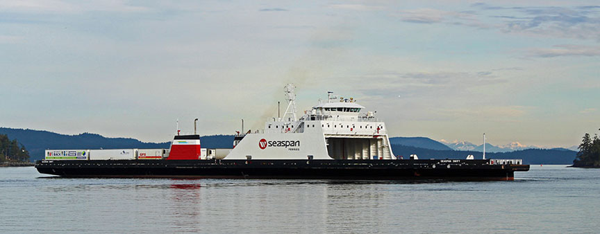
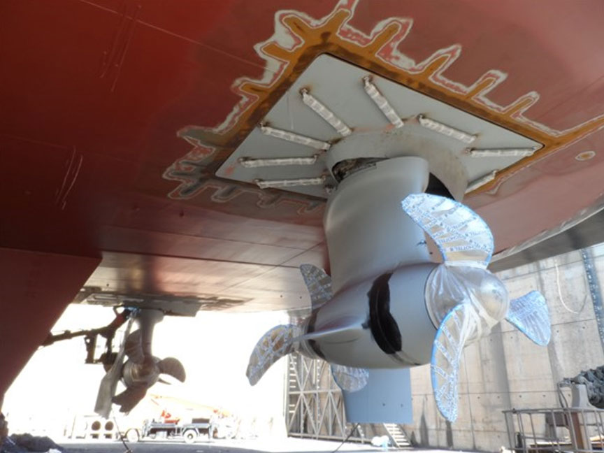
The Seaspan Swift (Figure 1) is a single-ended roll-on/roll-off cargo ferry.Footnote 1 It has an open vehicle deck and a superstructure located forward of amidships that contains a bridge and crew accommodation. The vessel has 2 dual-fuel (liquefied natural gas and marine diesel oil) constant-speed engines. Each engine feeds a generator and switchboard equipment that power variable speed electric motors (2 in total). Each motor drives an independent azimuth thrusterFootnote 2 (hereafter referred to as a pod). The pods have 3-bladed propellers located at either end (Appendix A). The pods provide both propulsion and steering.
The propulsion and steering controls are located on the bridge. The vessel has 2 manual steering controls: a wheel and pod handles. The pods have varying degrees of rotation depending on which type of mode (harbour/sea) or steering control (wheel/pod) is in use.Footnote 3 The vessel also has an autopilot.
The bridge is fitted with navigational equipment including radar displays, a magnetic compass and a gyrocompass, an electronic chart display and information system, a global positioning system, autopilot, a very high frequency (VHF) radiotelephone, an echo sounder, an automatic identification system, and a speed log. Controls for the ballast water system are located on the bridge. The vessel is fitted with a voyage data recorder (VDR), 2 bow thrusters, and 2 anchors. The anchors can be released remotely from the bridge or locally.
1.3 History of the voyage
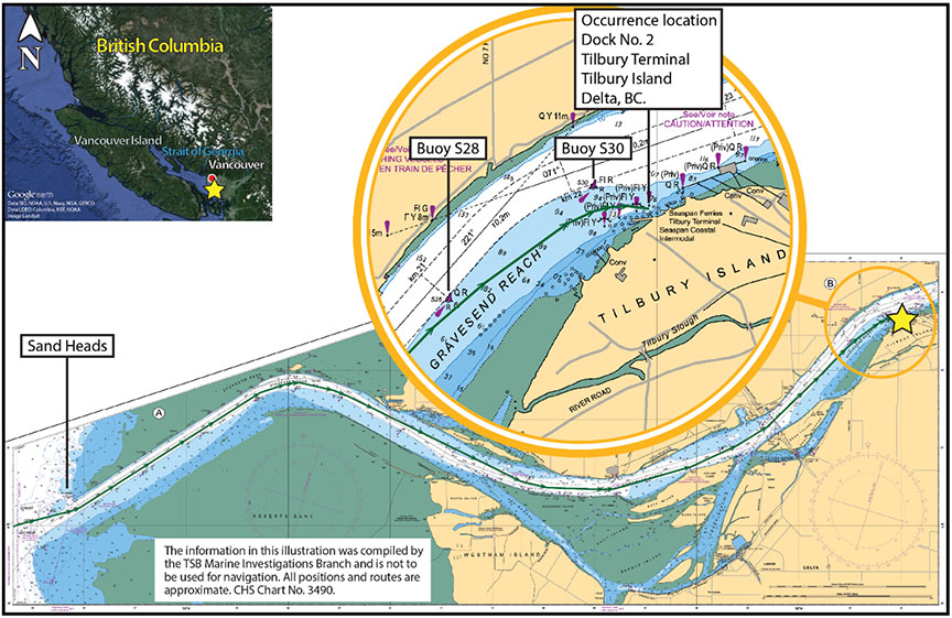
On 15 November 2017, at about 1250,Footnote 4 the Seaspan Swift, with 10 crew members on board, departed the Swartz Bay terminal in Victoria, British Columbia, bound for Seaspan Ferries' Tilbury terminal on Tilbury Island, Delta, British Columbia (Appendix B). The on-duty crew consisted of the relief master, the chief officer, 1 engineer, 1 cook, and 1 deckhand. The regular master,Footnote 5 1 engineer, 2 deckhands, and the second officer were also on board, but were off duty. Prior to departure, after a brief handover, the relief master took over the commandFootnote 6 from the regular master. During the crossing, the vessel was in sea modeFootnote 7 and on autopilot.
When the vessel was approximately 3 nautical miles from Sand Heads (Appendix B), the chief officer placed the engine room on standby for arrival. The vessel's steering was switched from autopilot to the wheel, which the deckhand was using. At this time, the vessel's speed was 16 knots, and the bridge was crewed by the relief master, the chief officer, and a deckhand. Around 1509, the deckhand at the wheel was relieved by another deckhand, who continued steering using the wheel.
At 1514, the relief master tried to communicate with the Tilbury terminal via VHF radiotelephone, but the line was busy. The chief officer then used the company cellphone to call the terminal for berth allocation and was assigned the No. 2 berth. He also checked the tide conditions required for berthing and started ballasting operations from the bridge.
At about 1517, while the vessel was approaching Buoy S28 (Appendix B) at 16 knots, the relief master took over the wheel from the deckhand, who left the bridge to begin preparations for berthing. At this time, the chief officer was monitoring the ballasting operation, the relief master's activities, and the vessel's progress.
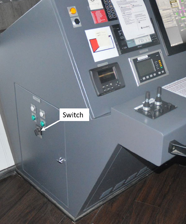
At approximately 1518, the regular master came up to the bridge in preparation to take over command from the relief master once the vessel was berthed. The regular master stood by on the port side of the bridge control console near a protruding electrical switchFootnote 8(Figure 2).
At 1519, the regular master's knee made contact with the switch.Footnote 9 This momentarily turned off both radar displays and activated the bridge windshield washer, which sprayed water onto the bridge windows.
Within moments, the chief officer and the regular master identified the switch as the source of the problem.Footnote 10 The regular master ensured that the switch was in the correct operating position. The relief master, still at the wheel, and the chief officer then verified that all the bridge equipment was operating normally, including the radars. The radars had stopped scanning and were not initialized by the bridge team. The chief officer and both masters discussed the malfunction and some of the equipment powered by this switch. The bridge team did not know where the equipment powered by this switch was indicated; the relief master had to rely on the regular master and chief officer to tell him which equipment it powered. Power was restored to the radar displays, and the crew then returned to their respective stations and tasks. As the voyage progressed, the relief master continued to steer using the wheel and was mentally checking whether all of the required equipment had been reset.
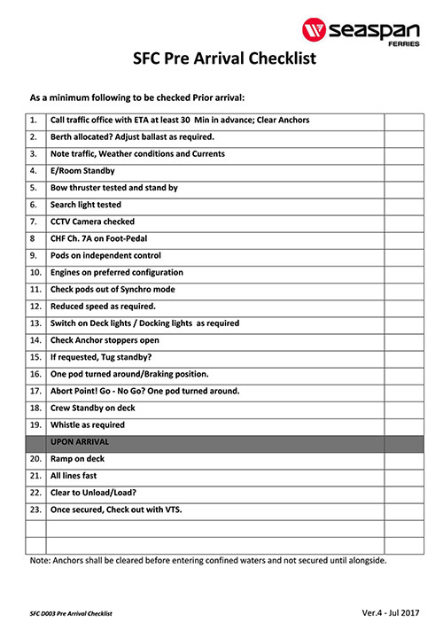
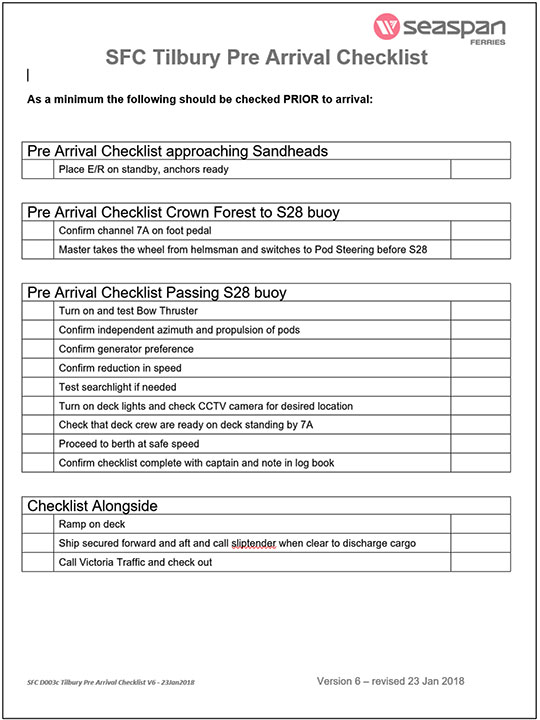
At 1522, the chief officer started the pre-arrival checklist (Appendix C). He completed a few items on the checklist, calling them out as he did so. The relief master responded to some of them. Soon after, the relief master switched on the bow thrusters.
At 1523, the chief officer continued the checklist items and asked aloud whether the pods were on independent control (that is, whether steering control had been switched to the pod handles). The relief master did not respond. Neither the relief master nor the chief officer resumed the checklist after this point.
At around 1523, the vessel's speed dropped below 8 knots, which caused the harbour mode alarm to sound. This was heard by the chief officer and confirmed by the relief master, who acknowledged the alarm by pressing the harbour mode button.
At around 1525, the vessel passed Buoy S28 at 7.2 knots. The chief officer continued with ballasting.
At around 1527, the relief master on the Seaspan Swift communicated with the master on the Seaspan Reliant, which was outbound from berth No. 2, and agreed on a passing arrangement whereby the Seaspan Reliant would pass outside Buoy S30 (Appendix B).
Meanwhile, the relief master began monitoring 2 downbound tugs with a barge that were entering the channel from a terminal located across the river from the Tilbury terminal. The Seaspan Greg, another company vessel, was inbound for berth No. 4, ahead of the Seaspan Swift. At some point, the masters of the Seaspan Reliant and the Seaspan Swift communicated to slightly modify the passing arrangement so that the Seaspan Reliant would pass inside Buoy S30, allowing more room for the 2 tugs and the barge that were now in the channel.
At 1531, around Buoy S30, the relief master used the wheel to manoeuvre the Seaspan Swift slightly and allow room for the Seaspan Reliant to pass between Buoy S30 and the Seaspan Swift. At 1533, the relief master used the bow thrusters to align the vessel for the final approach to the No. 2 berth. Soon after, the relief master communicated with Marine Communications and Traffic Services to confirm that the vessel was arriving at the Tilbury terminal.
At 1532, the vessel was aligned with the No. 2 berth and was approximately a ship length (about 145 m) away from the berth. The relief master then placed his hand on the port pod handle, rotated it 180°,Footnote 11 and increased thrust on the port pod to slow the vessel's forward speed of 3.2 knots.
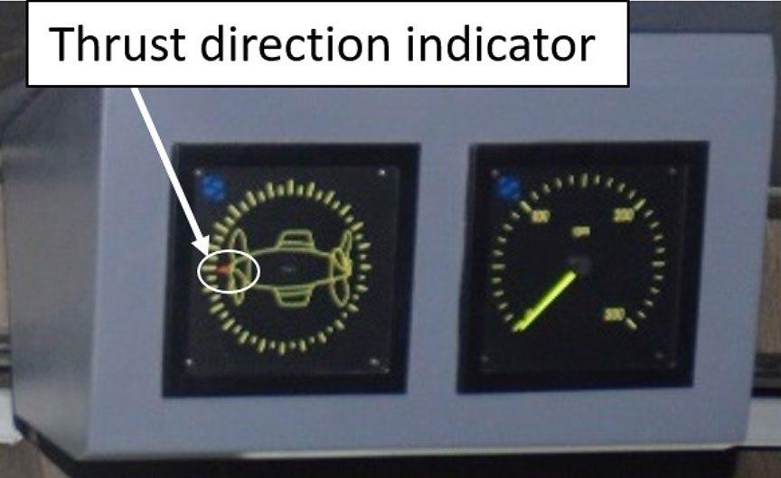
However, the relief master noticed that the vessel's speed increased. Given that the vessel's speed was not reducing, he looked at the display for the port pod thrust direction indicator, located above the bridge window.Footnote 12 The indicator was at the 12 o'clock position, indicating forward thrust. Attributing the vessel's response to wind and tide conditions, he increased the thrust further to arrest the vessel's forward movement, but the vessel sped up to 4.5 knots. The relief master then realized that the vessel's steering control was still set to the wheel. He quickly switched the steering control over to the pod handles,Footnote 13 and turned the starboard pod handle to 180° to attempt a crash stop.Footnote 14 He was applying astern thrust on both pods when, at 1534, the vessel struck the berth at about 4.1 knots. The anchors were on standby but not deployed.
Following the striking, the chief officer checked the status of the engine room and advised the chief engineer that the vessel had experienced a hard landing. One of the off-duty deckhands and the cook sustained minor injuries as a result of the striking.
1.4 Damage to the vessel
The Seaspan Swift's port bow hull structure sustained damage in way of the forepeak, including the main deck and stiffeners.
1.5 Damage to the terminal
The terminal ramp was pushed back into berth No. 2, and both sustained damage.
1.6 Personnel certification and experience
The relief master held a Master Mariner certificate of competency. The certificate was first issued in 1996. The relief master had sailed as a master on various Seaspan vessels since 2005, and normally worked on the Seaspan Swift's sister vessel, the Seaspan Reliant. The relief master had completed familiarization training on the Seaspan Swift in October 2017. From the time of his familiarization training until the day of the occurrence, he had worked a total of 6 days on the Seaspan Swift. He had completed bridge resource management (BRM) training in October 2000.
The chief officer held a Chief Mate, Near Coastal certificate of competency issued in February 2013. He had been employed by the company since 2001 and had been sailing as a chief officer since April 2013, mostly on the company's other vessels. The chief officer did not have BRM training at the time of the occurrence.
The deckhand held a Bridge Watch Rating certificate issued in December 2016 and had been sailing since 2013. He had joined the company in 2016.
The regular master held a Master, Near Coastal certificate of competency and had sailed as a master since 2003 on various vessels owned by the company. He had joined the Seaspan Swift in January 2017. The regular master completed BRM training in April 2009.
1.7 Vessel certification and survey
The Seaspan Swift carried all of the required certificates for a vessel of its class and for the intended voyage. The vessel was built in 2016 and held a certificate of classification issued by Bureau Veritas on 29 December 2016.
1.8 Environmental conditions
The weather at the time of the occurrence was clear with good visibility of approximately 16 nautical miles. There was a south-southeasterly wind of about 5 knots and southeasterly swell of approximately 0.1 m with a flood tide. The air temperature was 9 °C and the surface water temperature was approximately 8 °C.
1.9 Steering and propulsion controls
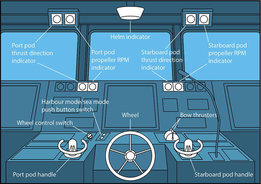
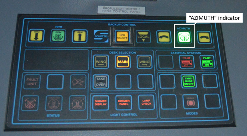
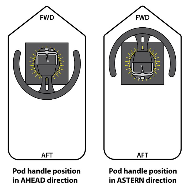
The Seaspan Swift and its sister vessel, the Seaspan Reliant, were originally designed with 2 types of manual steering controls: a wheel and pod handles. The pod handles, located on either side of the bridge centre console (Figure 3), can turn the pods independently or in synchro mode.Footnote 15 The pods are capable of rotating horizontally 360° in either direction. When the steering control is set to the pod handles, an indicator on the propulsion control panel, labelled “AZIMUTH,” lights up (Figure 4).
1.9.1 Harbour mode and sea mode
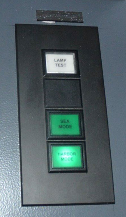
The vessel has autopilot and 2 manual steering controls (wheel and pod). Both autopilot and the 2 manual steering controls have 2 modes: harbour and sea (Figure 5). Sea mode is usually used for transiting in open waters; harbour mode is used for manoeuvring in restricted waters and berthing. When the vessel's speed exceeds 8 knots, the harbour/sea mode alarm sounds to alert the master that he or she has the option to put the vessel in sea mode. When autopilot or pod steering control is used in sea mode, the pods are restricted to moving ±30° from the centreline.Footnote 16
When the vessel's speed drops below 8 knots, the same alarm sounds to alert the master that he or she has the option to put the vessel in harbour mode. When the vessel is in autopilot or pod steering control and is in harbour mode, the pods can be turned to any angle. The unrestricted rotation of the pods in harbour mode also provides the ability to perform a crash stop. The increase or decrease in speed is indicated by an intermittent beeping alarm. The sound of the audible alarm for harbour/sea mode is the same as the sound of the audible confirmation when the operator switches the steering control from the wheel to the pod handles, and vice versa.
On the Seaspan Reliant, which was always operated in harbour mode, the harbour/sea mode changeover function was not connected. This meant that there was no audible alarm when the vessel's speed dropped below 8 knots or increased to more than 8 knots.
1.9.2 Wheel steering
The other vessels in the company's fleet that were constructed before the Seaspan Swift and the Seaspan Reliant, such as the Seaspan Challenger, the Seaspan Pusher, the Princess Superior, and the Seaspan Greg, have conventional wheels for steering the vessels.
The deckhands steer the vessels under the master's orders until the vessels get close to the terminals, at which time the master takes over and manoeuvres into the berth.
When the Seaspan Swift and the Seaspan Reliant were designed, the company included electrically operated steering wheels on each vessel. The wheel is used to steer the pods in unison and restricts the angle of the pods to ±45°. The wheel is normally used when the vessel is in sea mode.
1.9.3 Wheel control switch
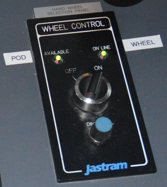
The wheel was integrated such that the operator can switch between steering systems, with only 1 system in operation at any given time. To change the steering control from the pod handles to the wheel or vice versa, a control switch with visual indicators (green LED lights) was installed (Figure 6). The green LED on the left-hand side indicates the availability of electrical power supply to the wheel, and the green LED on the right-hand side indicates when wheel steering is selected. Placing the vessel on wheel steering isolates steering control from the handles of both pods. The operator can still rotate the pod handles, but this action will not have any effect on the pods. When the operator switches the steering from the pod handles to the wheel or vice versa, there is an audible confirmation in the form of a single beep. When the wheel is deselected, the steering automatically transfers to the pod handles and the green light on the right side of the wheel control selection panel extinguishes.
1.9.4 Speed control levers
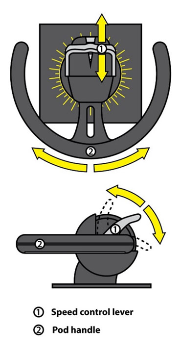
Levers for increasing or decreasing the speed of the propellers are located on the pod handles (Figure 7 and Figure 8). The levers are unidirectional and can move only from 0° (located at the centre of the lever) to a maximum of 90° (located at 1 end of the lever). The speed control levers are the only means of increasing or decreasing propulsion on the vessel and are used either when the operator is steering with the wheel or when the operator is steering with the pod handles. The propellers rotate in 1 direction only.
1.9.5 Steering and propulsion control indicators
There are 4 sets of indicators on the bridge to show thrust direction and the rpm of the pod (Figure 9). Two are located on the main console near each of the pod handles, and 2 are located above the forward-facing bridge front windows (the indicator for the port pod is on the left side and the indicator for the starboard pod is on the right side). The thrust direction indicators show an unmarked 360° rotary scale with a 2-propeller pod image and a red triangle-shaped pointer that indicates the direction of thrust from the pod (Figure 9).
The red triangle-shaped pointer is 6 mm high, and the typical distance between where the operator stands and the displays on the bridge front windows is approximately 210 cm.
The formula for calculating the visual angle (VA) is as follows: VA (minutes of arc) = (3438 × height) / distance from the eye.
The VA of the red pointer from the longest anticipated viewing distance is 9.8 minutes of arc. ASTM International, an organization that develops technical standards, recommends a standard of 16 minutes of arc.Footnote 17 This standard is important for legibility. An insufficient VA that depends on font size and distance makes the red pointer difficult to read, as well as makes it appear similar at 0° and 180° from the operator's vantage point.
1.10 Bridge ergonomics
Bridge ergonomics are the design and layout of controls and displays to optimize efficiency and usability while minimizing the risk of operator error. Inadequate bridge ergonomics can negatively affect an operator's situational awarenessFootnote 18 and, consequently, the vessel's navigability and safety. An operator's attention and information-processing capabilities are at near maximum usage in situations when cognitive workload is high, such as during the execution of a berthing manoeuvre, particularly in the presence of other vessels.
A vessel of the Seaspan Swift's size and voyage classification is required to comply with the principles relating to the design and arrangement of navigational equipment specified in the Navigation Safety Regulations.Footnote 19 Various organizations also provide guidance documents on ergonomic design of navigation bridges intended to inform vessel designers of principles and data relevant to the design of navigation bridges.Footnote 20,Footnote 21,Footnote 22,Footnote 23,Footnote 24 Among other things, these documents specify that controls should be adjacent to related displays and located in a way that allows the information on the displays to be read easily during the operation of the controls (for example, the font or symbol size should be compatible with viewing distance). Controls should be designed in a way that prevents accidental activation and should provide visual, aural, or tactile feedback to indicate that controller input has been registered.
1.11 Voyage data recorder
The purpose of a VDR is to record and safeguard critical information and parameters relating to the last hours of a voyage to help relevant authorities with their investigations into the causes and contributing factors of an occurrence. A VDR continuously records bridge audio as well as data such as the time, vessel heading and speed, gyrocompass, alarms, VHF radiotelephone communications, radar, echo sounder, wind speed and direction, and rudder/engine orders and responses.
The Seaspan Swift was fitted with a VDR as required by regulation. Following the occurrence, TSB investigators downloaded the information from the VDR, but found that the data was incomplete and did not include rudder orders and response, engine orders and response, main alarms, or water depth. The VDR data also showed that the electronic chart display and information system alarms were off. The bridge audio recordings were unclear, and some of the conversation between crew members was not picked up by the VDR microphones on the bridge.
1.12 Safety management system
The principal objectives of safety management on board vessels are to ensure safety at sea, prevent human injury or loss of life, and avoid damage to the environment and property. A documented, systematic approach to safety management helps ensure that individuals at all levels of an organization have the information and the tools that they need to make sound decisions during both routine and emergency operations. One of the objectives of a safety management system (SMS) is to assess all identified risks to an organization's vessels, personnel, and the environment, and to establish appropriate safeguards. In addition, a vessel operator should carry out internal safety assessments to evaluate the effectiveness of the SMS and to verify whether the safety and pollution prevention activities comply with it.
Because the Seaspan Swift and the Seaspan Reliant have liquefied natural gas propulsion, Transport Canada (TC) required both vessels to have an audited and certified SMS in accordance with the International Safety Management code.Footnote 25 Both the Seaspan Swift and the Seaspan Reliant had an SMS, including a shipboard management manual (SMM) that was first issued on 31 October 2016.
1.12.1 Familiarization and training
Section 6.2 of the SMM requires all crew members to be properly familiarized on board a vessel before they take their first regular watch. To facilitate this familiarization, the company provides a checklist to be used, along with instructions for the checklist. For an officer, a minimum of 5 days is allocated for familiarization. The familiarization period can be shortened at the master's discretion if a person has worked on a sister vessel.
The following observations were made about the familiarization training documents for the relief master and chief officer with respect to the Seaspan Swift:
- Relief master:
- The relief master started his familiarization training on the Seaspan Swift on 05 October 2017; the checklist completion date was 19 October 2017.
- On 12 October, the regular master granted the relief master clearance to work on the Seaspan Swift.
- Chief officer:
- The chief officer was familiarized on the Seaspan Swift using a checklist dated June 2016.
- The chief officer underwent familiarization training on the Seaspan Swift in December 2016, January 2017, and February 2017. His checklist was not countersigned by the trainer, the designated person ashore, or a designate, nor was there a line on the checklist to indicate the date when he was cleared.
- The chief officer was cleared by the regular master as meeting the minimum required criteria to maintain independent watches on the Seaspan Swift.
The checklists used to familiarize the relief master and chief officer are generic. Therefore, they do not mention the manual steering controls (i.e. the wheel and the pod handles) or the procedure to switch between the two that is unique to the Seaspan Swift and the Seaspan Reliant. They also do not cover
- the pod/wheel changeover procedure;
- pod/rpm indicators; or
- harbour mode and sea mode.
1.12.2 Pre-arrival checklist
The company had developed a generic pre-arrival checklist that was on board the Seaspan Swift (Appendix C). The checklist included a step requiring the pods to be switched to independent propulsion, which necessitates transferring steering control from the wheel to the pod handles, but did not specify when this was to be done. The regular master on the Seaspan Swift had developed a practice of changing over the vessel's steering control from the wheel to the pod handles at or before Buoy S28, when the vessel's speed dropped below 8 knots. The relief master, meanwhile, had a practice of changing over the steering control to the pod handles when he deemed it necessary. The checklist did not specify whether or when the vessel's alternate propulsion and steering systems, such as applying an astern thrust, were to be tested.
1.12.3 Bridge resource management
Bridge resource management (BRM) is the effective management and use of all resources, human and technical, available to the bridge team to ensure the safe completion of the voyage. BRM encompasses skills, knowledge, and strategies on effective communication, workload management, problem solving, decision making, teamwork, and situational awareness, especially during critical operations.
Effective communication is a key concept of BRM because it helps to establish a shared mental model among the bridge team. When the bridge team has a shared understanding of how manoeuvres will proceed, they are able to work together to accomplish these manoeuvres, identify operational or human errors, and intervene as required.
The company had listed duties for the master and the officers and crew in the SMM, but did not have any procedures or guidelines to ensure effective BRM.
1.13 Previous TSB recommendations on bridge resource management
Following a 1995 TSB study entitled Safety Study of the Operational Relationship Between Ship Masters/Watchkeeping Officers and Marine Pilots, the Board made the following 2 recommendations regarding BRM training:
the Department of Transport require that the initial training syllabus for all ship officers be modified to include demonstration of skills in Bridge Resource Management.TSB Recommendation M95-09
the Department of Transport require that all ship officers demonstrate skills in Bridge Resource Management before being issued Continued Proficiency Certificates.TSB Recommendation M95-10
In response to Recommendation M95-09, TC revised TP 4958Footnote 26 in 2016 to incorporate the competencies and knowledge related to watchkeeping officers outlined in the International Convention on Standards of Training, Certification and Watchkeeping for Seafarers for BRM. The new curriculum covers both operational and management competency demonstration in the Simulated Electronic Navigation training courses required for watchkeeping officers at Operational Level (SEN-O) and for masters and mates in the leadership, teamwork, and managerial skills training course. Once the proposed TP 4958 training curriculum is in force, the initial training syllabus for all vessel officers will include the requirement to demonstrate skills in BRM. The TSB assessed the response to this recommendation as showing Satisfactory Intent.
In response to Recommendation M95-10, TC revised TP 4958 to develop the new training required for the leadership, teamwork, and managerial skills course that will be mandatory for any candidates who want to obtain a new certificate of competency (CoC) or to upgrade their current CoC to a higher CoC. As of 01 January 2017, TC has a policy that requires any candidates who want to obtain a CoC for the first time or upgrade their current CoC to a higher CoC to complete the relevant leadership, teamwork, and managerial skills training course.
However, candidates who want to renew their CoC (which is required every 5 years) will still not be required to obtain training in BRM. The TSB assessed the response to this recommendation as Satisfactory in Part.
1.14 Previous occurrences
Previous occurrences reported to the TSB in the past 10 years have identified issues with respect to bridge ergonomics and BRM.
1.14.1 Bridge ergonomics
M17C0108 – On 16 June 2017, the tanker Damia Desgagnes, with 20 people on board, grounded in the St. Lawrence Seaway near Morrisburg, Ontario, after unexpectedly losing main engine propulsion. The main engine inadvertently shut down as a result of the accidental activation of the main engine shutdown button on the integrated alarm monitoring and control system touch screen on the bridge.
M16C0005 – On 22 January 2016, the container vessel MSC Monica ran aground in the St. Lawrence River 1 nautical mile north-northeast of Deschaillons-sur-Saint-Laurent, Quebec. The pilot on board was unfamiliar with the configuration of the non-follow-up tiller and unintentionally applied the helm order hard-a-starboard instead of hard-a-port. The vessel sustained minor damage to the hull and major damage to the 4 propeller blades. The investigation found that if the ergonomics of critical shipboard equipment, such as a non-follow-up tiller, are designed in a way that is confusing or contradicts expectations, there is a risk that a user who is unfamiliar with their configuration will operate them incorrectly.
M14C0045 – On 22 April 2014, the chemical/products tanker Halit Bey was proceeding upbound in the St. Lawrence River, under the conduct of a pilot, when steering control was lost. The vessel veered to port and exited the navigational channel, running aground on the south side of the river off Grondines, Quebec. Steering control from the steering wheel was disabled likely when the unprotected non-follow-up joystick was inadvertently moved, activating the autopilot override and alarm. The investigation found that if critical bridge systems, such as steering gear control systems, are not designed and arranged to be straightforward and intuitive with safeguards to minimize human error, there is a risk that an operator will not be able to respond quickly and effectively in an emergency.
1.14.2 Bridge resource management
M14C0106 – On 12 June 2014, the self-discharging bulk carrier Atlantic Erie ran aground 1.5 nautical miles southeast of the outer piers at Port Colborne, Ontario, after power interruptions to the bridge. The master was not using all available bridge resources to monitor the vessel's progress, and the vessel proceeded off its intended course for approximately 15 minutes. There were no injuries or pollution, but the vessel sustained damage.
M12L0147 – On 28 November 2012, the bulk carrier Tundra exited the navigation channel and ran aground off Sainte-Anne-de-Sorel, Quebec. The pilot and other members of the bridge team were not exchanging information pertaining to the navigation of the vessel; therefore, the bridge team was unaware of a planned course change. The investigation found that if bridge team members do not share a complete and common understanding of a vessel's intended route and do not continuously exchange information, there is a risk that the bridge team members' ability to monitor a vessel's progress may be compromised.
M11N0047 – On 24 November 2011, the offshore supply vessel Maersk Detector was using dynamic positioning while loading cargo from the mobile offshore drilling unit GSF Grand Banks in the White Rose oil field. Weather was deteriorating at the time, with increasing swells arriving from the south. The vessel did not maintain position, and the port stern of the Maersk Detector struck the port aft intermediate column of the GSF Grand Banks, holing both the vessel and the rig. The bridge officers did not work as a team, nor did they make full use of the data available on the dynamic positioning consoles to maintain the vessel's distance from the rig. Consequently, their awareness of the imminent striking was delayed, and this prevented adequate evasive action from being taken.
Analysis
The investigation determined that the vessel struck the berth after the relief master increased thrust with the port pod incorrectly positioned opposite the intended direction. The report will analyze bridge ergonomics, familiarization training, bridge resource management (BRM), and the relief master's mental model at the time of the occurrence.
2.1 Factors leading to the striking
As the Seaspan Swift neared the terminal for berthing, the relief master was coordinating a passing arrangement with the Seaspan Reliant, monitoring other vessels in the vicinity, and mentally checking whether all of the required equipment had been reset following the unexpected power interruption. The chief officer started the pre-arrival checklist with the master, but when they reached the step to switch to independent control, the relief master did not respond because he had not yet carried out this step. The checklist was not resumed after this point, which led to a missed opportunity to remind the relief master to change over the steering control.
Just prior to berthing, the relief master turned the port pod handle to move the port pod to the astern position. However, because the steering control was still set to the wheel, the pod did not respond. The vessel was still thrusting ahead at 3.2 knots when the relief master increased the speed control lever to apply reverse thrust, which caused the vessel to speed up. Attributing this response to the wind and tide conditions, the relief master applied additional thrust, which caused the vessel to speed up unexpectedly toward the dock.
Although the relief master had looked at the port pod position indicator before applying thrust, he perceived that the indicator was showing the direction of the pod as being at 180° (reverse direction, 6 o'clock position) when it was in fact at 0° (forward direction, 12 o'clock position). Several factors may have contributed to this misperception: the small size of the red triangle-shaped pointer indicating thrust direction; the symmetrical shape of the pod at both the 0° and 180° positions; the low illumination setting of the thrust direction display; and the relief master's belief that the port pod was turned because he had just rotated the handle.
Furthermore, the harbour/sea mode changeover function and alarm were not connected on the Seaspan Reliant, and the audible indicator for harbour mode on the Seaspan Swift sounds the same as the audible indicator for selecting and deselecting wheel steering on the Seaspan Reliant. This may also have contributed to the fact that the relief master did not know which steering mode was selected.
When the relief master realized that he had not changed over from the wheel to the pod handles, he had approximately 21 seconds to attempt a crash stop before striking the berth. The relief master changed over the steering control about 1 second later. Because it takes 18 seconds for the pods to reverse direction from 0° to 180° (at which point the relief master could have applied full astern thrust to stop the vessel), and due to the proximity of the vessel to the berth, the vessel's forward momentum could not be arrested in time and the vessel struck the berth at a speed of 4.1 knots.
2.2 Bridge ergonomics
Even the most diligent and experienced bridge crew is subject to mistakes and oversights that characterize human behaviour. It is therefore essential that bridge controls and indicators be designed to prevent these errors to the extent possible. Good design takes into account concepts such as error tolerance, whereby a system is designed to minimize potential errors (such as by including locking features or protective coveringsFootnote 27), or user input acknowledgement, whereby physical feedback is provided to the operator to indicate that input via the controls has been successful.
2.2.1 Awareness of steering control
On the Seaspan Swift and its sister vessel, the Seaspan Reliant, there is no audible feedback to alert the operator and/or prevent him or her from the pod handles while the steering control is set to the wheel. A design that allows the operator to move the pod handles while the steering control is set to the wheel is conducive to mode errors.
At the time that the relief master rotated the port pod handle, there were visual cues to indicate that the steering control was set to the wheel. The position of the selector switch was set to wheel control, and both of the green LED lights above the wheel control switch were illuminated. The green “AZIMUTH” light to indicate that steering control was set to the pod handles was off. However, the azimuth light does not stand out among the other displays, and stands out even less when it is not lit. Invariably, the physical action of moving a control gives an operator the impression that the input was successful, even if it was not. As a result, the operator may not always look carefully at the available displays for confirmation of steering control.
The design of the labelling above the wheel control switch was not intuitive. As well, both green LED lights were illuminated when the steering control was set to the wheel, which could lead to confusion, given the location of the wheel and pod labels.
2.2.2 Thrust direction indicators
Clear, easy-to-read, and ergonomically positioned visual indicators facilitate the role of the navigator in visually confirming inputs and the status of bridge systems.
The port thrust direction indicator on the Seaspan Swift bridge window is approximately 210 cm from the operator, and the height of the red triangle-shaped pointer is 6 mm. The resulting visual angle of the red pointer from the longest anticipated viewing distance is 9.8 minutes of arc, which is significantly less than the recommended standard of 16 minutes. An insufficient visual angle that depends on font size and distance makes the red pointer difficult to read and makes it appear similar at 0° and 180° from the operator's vantage point. Further, the red triangle-shaped pointer does not extend to the centre of the scale, which would facilitate its readability.
2.2.3 Accidental activation of switches
The absence of safeguards over switches creates the possibility that accidental activation can occur. The consequences may range from confusion or distraction for the bridge team, as in this occurrence, to the shutdown of a critical system. Design features to prevent accidental activation of a switch may include locking features or coverings.Footnote 28
In this occurrence, the accidental power outage caused by a crew member's knee contacting an uncovered switch on the side panel resulted in a confusing and distracting situation on the bridge.
If bridge switches are not designed optimally, there is a risk of accidental activation, which could contribute to an accident.
2.3 Familiarization training
The familiarization checklists used to train the relief master and chief officer on the Seaspan Swift were generic and used fleetwide on all of the company vessels; as a result, they did not include specific mention of the vessel's steering controls (wheel/pod handles) or the procedure to change between the two. Although the TSB could not determine whether the relief master's and chief officer's familiarization contributed to this occurrence, the fact that the familiarization checklists were generic and did not reference the vessel's unique steering configuration, which differed from other vessels in the fleet, as well as other issues with the checklists mentioned previously, suggest shortcomings in safety management system documentation.
2.3.1 Bridge resource management
Effective BRM requires that bridge team members share information with one another to ensure that everyone has a common understanding of how the voyage will proceed, including berthing. Having this shared understanding enables bridge team members to act as backups for the primary navigator to help identify errors or inconsistencies. Sharing of information can be facilitated by approach briefs, by working as a team to complete checklists, and by calling out steps taken as they are completed so that everyone is aware of the vessel's progress.
At present, Transport Canada does not require all bridge team members to complete training in BRM. The current regulations require only those officers who obtain a new certificate or upgrade their current certificate of competency to complete BRM training. Officers who renew their existing certificate of competency (required every 5 years) are not required to complete BRM training. Consequently, in this occurrence, the chief officer was not required to obtain, and did not have, training in BRM.
In this occurrence, some shortcomings in BRM and in the tools available to the bridge team reduced the bridge team's ability to identify errors or inconsistencies during the approach for berthing in the occurrence voyage:
- The pre-arrival checklist was not vessel-specific and did not specify when the steering control was to be changed over and tested.
- The chief officer was occupied with ballasting while the vessel was approaching the berth, which reduced his monitoring of the relief master's activities.
- The relief master and chief officer began completing the pre-arrival checklist, with the chief officer calling out the items. The relief master did not respond consistently during this process and did not respond to the item about pods on independent control. Neither the relief master nor the chief officer resumed the checklist after this point.
It is important that bridge teams employ all measures and tools available to them to ensure the safe arrival of the vessel. This includes sharing information to ensure everyone on the bridge understands how manoeuvres will proceed, asking questions to obtain clarity around ambiguous procedures or decisions, completing checklists by calling out and confirming each item, and monitoring the primary navigator's actions to help identify errors or inconsistencies. Crews who work together regularly tend to develop shared understandings and familiarity with one another's practices, but maintaining good BRM practices is especially important when new or relief crew members are on board.
Training in BRM for all bridge team members facilitates a better understanding of these concepts and enhances their ability to communicate and work effectively to carry out the safe navigation of the vessel. In this occurrence, 2 of the 3 bridge team members had BRM training.
If not all bridge team members are required to take BRM training, or if bridge team members do not follow the key principles of BRM, they may not communicate and work effectively as a team, increasing the risk of accidents.
2.4 Voyage data recorder
The purpose of a voyage data recorder (VDR) is to create and maintain a secure, retrievable record of information indicating the position, movement, physical status, and control of a vessel. Objective data are invaluable to investigators seeking to understand a sequence of events and identify operational problems and human factors.
In this occurrence, the Seaspan Swift was fitted with a VDR, as required by regulation; however, the information obtained from the VDR was not complete. As a result, TSB investigators did not have access to recorded data about the pods' rpm, position, or movement during the final minutes before the vessel struck the berth. This information would have been invaluable for verifying the position of the pods at any given time in relation to the actions performed by the operator. The VDR also did not record main alarms, and the bridge audio recordings downloaded by TSB investigators were unclear, likely due to the position of the microphones on the bridge. Without this type of information, investigators have difficulty confirming the occurrence timeline and sequence of events.
If VDR data are not available to an investigation, the identification and communication of safety deficiencies to advance transportation safety may be precluded.
3.0 Findings
3.1 Findings as to causes and contributing factors
- As the Seaspan Swift approached the terminal, the relief master and chief officer started the pre-arrival checklist but stopped at the step requiring the pods to be on independent propulsion. They did not resume the checklist, leading to a missed opportunity to remind the relief master to switch over the steering controls.
- Because the steering control was still set to the wheel when the master turned the pod handle, the pod did not respond and remained thrusting in the ahead position.
- The relief master increased the speed control lever to apply reverse thrust, but this caused the vessel to speed up. Attributing this response to the wind and tide conditions, the relief master applied additional thrust, which caused the vessel to speed up unexpectedly towards the dock.
- Once the relief master realized that the steering control was not switched over to the pod handles, there was insufficient time for him to perform a crash stop given the vessel's proximity to the berth, and the vessel struck the berth at a speed of 4.1 knots.
3.2 Findings as to risk
- If bridge switches are not designed optimally, there is a risk of accidental activation, which could contribute to an accident.
- If not all bridge team members are required to take bridge resource management training or bridge team members do not follow key principles of bridge resource management, they may not communicate and work effectively as a team, increasing the risk of accidents.
- If voyage data recorder data are not available to an investigation, the identification and communication of safety deficiencies to advance transportation safety may be precluded.
4.0 Safety action
4.1 Safety action taken
4.1.1 Seaspan Ferries Corporation
Following the occurrence, Seaspan Ferries Corporation took the following actions:
- The loose connection in the 120V switch that triggered the momentary power interruption to the radar displays was repaired, and a protective arrangement was installed over the switch. The company also posted a list of equipment connected to this switch.
- Pre-arrival checklists that are specific to each terminal (Tilbury, Swartz Bay, and Duke Point) were created, and the steps were revised to include specific details about when the steering control should be set to the wheel and when it should be set to the pod handles (Appendix D).
- Input to the pre-arrival checklist was requested from company employees on significant changes that affect the fleet operations.
- On both the Seaspan Swift and the Seaspan Reliant, the style of thrust direction indicator was changed to one with a simplified representation of the thruster that clarifies the thrust direction.
- The steering control system design was modified so that when the steering control is set to the wheel, the pod handles must be set to the ahead position. If the handles are moved off position, an alarm sounds. This design was submitted and approved by the vessel's classification society and installed by the original equipment manufacturer.
- An investigation was initiated to determine why the vessel's voyage data recorder had not recorded certain data.
This report concludes the Transportation Safety Board of Canada's investigation into this occurrence. The Board authorized the release of this report on 28 November 2018. It was officially released 17 January 2019.
Appendices
