Derailment
Canadian National
Train Number A-442-51-08
Mile 52.1, Camrose Subdivision
Near Camrose, Alberta
The Transportation Safety Board of Canada (TSB) investigated this occurrence for the purpose of advancing transportation safety. It is not the function of the Board to assign fault or determine civil or criminal liability. This report is not created for use in the context of legal, disciplinary or other proceedings. See Ownership and use of content. Masculine pronouns and position titles may be used to signify all genders to comply with the Canadian Transportation Accident Investigation and Safety Board Act (S.C. 1989, c. 3).
Summary
On 08 July 2002, at 1328 mountain daylight time, Canadian National southward freight train A-442-51-08 derailed 2 locomotives and 13 cars at Mile 52.1 of the Camrose Subdivision, near Camrose, Alberta. No dangerous goods were released. There were no injuries.
Ce rapport est également disponible en français.
1.0 Factual information
1.1 The accident
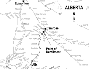
On 08 July 2002, at approximately 1040 mountain daylight time (MDT),Footnote 1 Canadian National (CN) freight train A-442-51-08 (the train) departed Edmonton, Alberta, for Calgary, Alberta. Figure 1 shows a location map of the area. The train consisted of 146 loaded cars, 6 empty cars, and 2 residue tank cars that last contained liquefied petroleum gas (UN 1075). In the locomotive consist, there were three operating locomotives, General Motors (GM) model SD60, SD70, and SD75 respectively, all equipped with extended range dynamic brake. As well, two isolated GM model GP 9 locomotives were trailing the operating locomotives. The train weighed 17 201 tons and was 9708 feet long. It had been inspected by two hot box and dragging equipment detectors en route. There were no alarms. The two isolated locomotives were not equipped with alignment control couplers.Footnote 2
The weather was clear, calm, and the temperature was 20°C. Approaching a six-degree curve at Mile 52.1 of the Camrose Subdivision, the train was descending a 0.7 per cent grade. The dynamic brakeFootnote 3 was engaged on the three leading locomotives and was being used to control train speed at 25 mph. All applied forces were balanced on the train.
Although not recorded by the event recorder, it was determined that the dynamic brake was generating in excess of 600 amperes of retarding force.Footnote 4
At 1328, while the locomotives were negotiating the curve, a train-initiated emergency brake application occurred. The two empty covered hopper cars immediately behind the locomotive consist derailed to the high side of the curve as the trailing two locomotives derailed but remained upright.
An empty flat car bypassed the covered hopper cars, jackknifed across the track and struck the trailing locomotive.
After conducting the necessary emergency procedures, the crew determined that the trailing truck of the fourth locomotive, the fifth locomotive, two empty covered hopper cars, five loaded intermodal flat cars and six (19 platforms) multi-platform intermodal carsFootnote 5 were derailed. At the point where the two empty covered hopper cars had derailed, to the high side of the curve, the east rail had rolled over to the field side and the west rail had remained upright but unsecured for about 250 feet. Both rails were rolled out to the field side under the fifth locomotive (CN 7271) and the trailing truck of the fourth locomotive (CN 7036). The entire derailment occurred within 900 feet, with rail cars derailed to the high side of the curve or jackknifed across the track. The last derailed car carried two containers carrying dangerous goods, but there were no leaks.
1.2 Recorded information
The locomotive event recorder on lead locomotive CN 5687 recorded that the train had been operated in dynamic braking (DB) at a constant speed of 25 mph for about five minutes (two miles). No air brakes were applied. Between 1328:26 and 1328:28, the train speed dropped 7 mph, from 25 mph to 18 mph, and the brake pipe pressure dropped from 84 to 14 pounds per square inch (psi), indicating that an emergency brake application had occurred. The independent brake was bailed off two seconds later at 1328:30. The locomotives stopped in 22 seconds, at 1328:50, having travelled 250 feet after the emergency brake application.
While the locomotive event recorder met existing regulatory requirements, it did not record end-of-train data, locomotive acceleration or dynamic brake level. This information is provided by some locomotive event recorder systems.Footnote 6
1.3 Equipment and track damage
The two derailed locomotives sustained minor damage. All derailed cars were destroyed. Approximately 860 feet of track was destroyed.
1.4 Crew information
The train crew consisted of a conductor and locomotive engineer who were qualified for their respective positions and met fitness and rest standards designed to ensure the safe operation of trains. The train was the longest and heaviest train the crew had operated on this subdivision.
1.5 The track
The Camrose Subdivision is a single main track that extends from Mile 0.0 in Edmonton, Alberta, to Mile 95.1 in Mirror, Alberta. Train movements are governed by the Occupancy Control System authorized by the Canadian Rail Operating Rules, and supervised by a rail traffic controller located in Edmonton. Permissible speed for freight trains from Mile 49.2 to Mile 58.4 was 25 mph.
Through the derailment area, the track consisted of 115-pound continuous welded rail laid on double-shouldered tie plates, secured to hardwood ties with two hold-down spikes and two gauge spikes per tie plate. The rail was anchored every second tie. Ballast was crushed rock with full cribs and 16-inch shoulders. The grade was 0.7 per cent descending and curvature was six-degree left-hand in the direction of travel. The track was in good condition and was in compliance with CN's Standard Practice Circulars and the Transport Canada-approved Railway Track Safety Rules.
The rail was tested by a rail flaw detection car on 31 May 2002. No internal defects were detected. The CN track geometry car inspection occurred on 10 June 2002 and no priority or urgent defects were identified. At about 0900 on 08 July 2002, the track maintenance foreman (TMF) visually inspected the track at the derailment location and no irregularities were noted.
1.6 Controlling train speed
Throttle modulation, the train air brake system and the locomotive DB system are used to control train speed. The train air brake system is the primary fail-safe system, designed to slow or stop a train using applications of the air brakes on the locomotives and cars throughout a train. Proper use of the air brake system results in a better distribution of retarding force throughout the length of the train.
The locomotive DB system creates a retarding force applied by the locomotives only. This force is transmitted sequentially from the front to the rear of a train. DB is a supplementary system well suited to controlling speed while trains are descending long grades. DB can be used in combination with the train air brakes when DB force is insufficient to control train speed. The use of DB has been recognized as a cost-saving practice for railway operations. Consequently, locomotive engineers are encouraged to use DB whenever possible. There was no information to suggest that DB on any of the three locomotives was inoperative.
1.7 In-train forces
Longitudinal buff forces occur when braking effort originates from the head end during DB. When there is no acceleration or deceleration, the buff (compressive) forces are proportional to the momentum of the train. When rolling stock is travelling on tangent track and the couplers remain aligned, the longitudinal buff force from one car is transmitted through the couplers, along the car body centreline, to the next car. The track structure is designed with curvature elevations to maintain in-train forces close to the car body centreline over the centre of the track. However, when rolling stock traverses curved track, each coupler takes an angle to the car body centreline, resulting in lateral force being applied perpendicularly to the rail at the wheels.
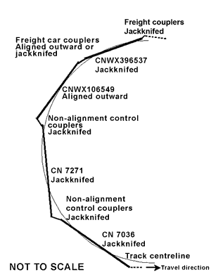
When a train is in buff on curved track, the car bodies and couplers are either aligned to one side or jackknifedFootnote 7 (see Figure 6). Aligned to one side of a car body means that the two trucks of the car are against the same rail, either high or low rail, while jackknifing of a car body means that the two trucks of the car are against opposite rails. Aligned to one side of two couplers occurs between the trailing truck of one car and the leading truck of the adjacent car; the two trucks are against the same rail, either high or low rail. Jackknifing of two couplers occurs when the two trucks are against opposite rails. In both jackknifing cases, the centreline of the car body takes an angle against the centreline of the track.
Jackknifing of the couplers increases draw bar angles more than jackknifing of car bodies because the distance between articulation points is much shorter. When couplers under buff forces take a jackknifing position, the draw bar angle is constrained by the alignment control of the couplers and by the wheels against the rails. Longitudinal force transformed to lateral force in this manner can cause track displacement at the truck locations and lead to more jackknifing and larger draw bar angles. The increased draw bar angle can only be limited by the swing restraint of the alignment control couplers or bolster stops and/or strong track at its lateral displacement limit. Derailment by either wheel climb, car or rail rollover can result.
1.8 Railway operating instructions
The following references to the CN Locomotive Engineer Operating Manual and General Operating Instructions (GOI) are pertinent to the control of train speed with DB.
Section F7.4.1 of the Locomotive Engineer Operating Manual states in part:
High DB capacity locomotives in consists of three or more locomotives should be limited to a maximum of 500 Amps when the head-end is entering a turnout, crossover or curve until at least half the train has passed through.
Section F7.4.2 of the Locomotive Engineer Operating Manual states:
This is particularly important when only DB is used to control train speed and when the train has both empties or light loads on the head-end and heavy loads on the rear-end.
Under these conditions, a harsh bunching of slack or run-in combined with track curvature can cause very high lateral forces and/or cause derailment or damage to the track structure.
Section H1.1, item 5, of the Locomotive Engineer Operating Manual states:
Dynamic brake must be fully utilized as the initial braking force. The use of dynamic brake will ensure less wear/damage to equipment components and improve fuel efficiency.
Section H1.4 of the Locomotive Engineer Operating Manual states in part:
Care must be exercised when using the independent brake or dynamic brake without the train brakes to effect a slowdown or stop, particularly with three or more units in the consist.
Section 6.4 of CN's GOI states in part:
Extreme caution must be exercised when making bunched stops or decreasing speed, with locomotive consists, giving due consideration to grade, curvature and weight distribution of the train consist. The cautions highlighted in the foregoing are particularly important when:
- (a) Any locomotives which are not equipped with alignment control draft gear are in the consist.
- (d) The cars next to or near the locomotives are empty cars or a combination of short and long cars.
Section 6.8(a) of CN's GOI states:
During planned braking operation, if one or more operable dynamic brakes are available, every effort must be taken to use this method of controlling train speed.
Section 6.8(b) of CN's GOI states:
Locomotive consists operating with three or more units equipped with dynamic brakes have the capability of producing extremely high braking forces. If braking forces are high, they become critical on descending grades and at turnouts, crossovers and sharp curves.
Locomotive engineers are reminded to exercise caution in order to keep the braking effort low during these situations.
CN provides a Best Practices Train Handling Guide based on an optimum train run for its main corridor subdivisions to assist locomotive engineers in choosing the best method of controlling trains. However, on the Camrose Subdivision, no guide was provided to locomotive engineers to assist in operating trains.
On 10 July 2002, following this occurrence, CN issued Operating Bulletin 129 entitled New Instruction: Yard Service Locomotives Handled on Trains. The bulletin lists the locomotives not equipped with alignment control couplers and instructs that:
When any of the [. . .] locomotives listed are handled in train service behind the working locomotive consist AND trailing tonnage exceeds 4000 tons, it must not have any other locomotive [. . .] anywhere in the train behind the controlling locomotive.
1.9 CN's locomotive marshalling practices
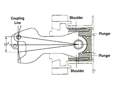
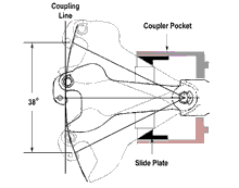
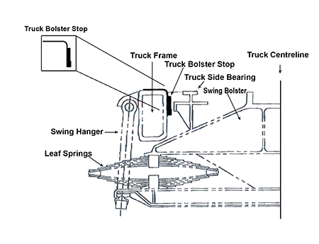
The locomotive consist was dispatched from the Walker Yard diesel shop with two isolated locomotives marshalled behind the operating locomotives. These two isolated locomotives were serviced at the Walker Yard diesel shop in Edmonton and were regularly transferred on train 442 to work in Calgary's Sarcee Yard. Both locomotives were general purpose (GP 9) freight units used for switching the yard and industrial tracks. These two locomotives were not equipped with alignment control couplers or bolster stopsFootnote 8 (see Figures 2, 3 and 4). Locomotives without alignment control couplers or bolster stops provide a greater range of coupler movement while negotiating tight curves in yards and industrial spurs. The train's locomotive consist was marshalled in accordance with CN's GOI and the Locomotive Engineer Operating Manual that require that dead or idling locomotives be handled immediately behind the locomotives assigned to the train.
1.10 Industry practices regarding locomotive marshalling
The Association of American Railroads (AAR), the locomotive manufacturer and other railways recommend the following practices to avoid jackknife-type derailments when trains have locomotives not equipped with alignment control couplers in the locomotive consist.
The AAR research reportFootnote 9 entitled Track Train Dynamics to Improve Freight Train Performance states, in part, that:
To reduce potential jackknifing tendencies, units without either alignment control couplers or other anti-jackknifing devices, operated in multiple, should be placed, where possible, at least four units from the closest car.
A subsequent AAR reportFootnote 10 entitled Train Make-up Manual states, in part:
Some early model locomotives were not equipped with coupler alignment control. These locomotives can become a problem because of their tendency to jackknife if they are entrained behind other locomotives that can generate large dynamic brake forces.
GM, the locomotive manufacturer, published Locomotive Pointers dated 26 October 1981, which recommends that:
Units with pin-type couplers and no alignment control features must have bolster stops applied to allow operation in consists with units capable of high dynamic braking effort (but not over 200,000 pounds).
Bolster stops must be applied to GP and "F" type units that do not have alignment control features associated with their pin-type couplers before such units are subjected to the buff loads resulting from high dynamic braking effort. . . .
These recommendations apply whether the GP or "F" units are powered or are merely "dead" in the consist.
To prevent the possibility of jackknifing of locomotives and cars next to the locomotive, Canadian Pacific Railway's (CPR) GOI, Section 15, Item 5.3, prescribes the following practice:
- When locomotives not equipped with coupler alignment or bolster stops are marshalled as the first and/or second locomotive of a consist, and all other locomotives are equipped with coupler alignment control or bolster stops: no special operating instructions are required.
- When three or more locomotives not equipped with coupler alignment control or bolster stops are in a locomotive consist, they are to be marshalled ahead of the locomotives with coupler alignment control or bolster stops. The use of independent brake on curves must be avoided.
- When locomotives without coupler alignment control or bolster stops are not marshalled according to a) or b) above, the use of dynamic brake and or independent brake on curves must be avoided.
Burlington Northern Santa Fe Railroad Air Brake and Train Handling RulesFootnote 11 state in part:
Locomotives without alignment control couplers must not be used as helper locomotives or placed ahead of more than 5,000 trailing tons when locomotive consist exceeds a rating of 18 power/dynamic brake axles unless:
- Locomotive with alignment control coupler is coupled against train.
- No two locomotives without alignment control are coupled together.
1.11 CN's train marshalling practices
CN's Train Service Plan for train 442 indicated a maximum train length of 6000 feet with no restriction on tonnage. Train Service Plans are used to specify a combination of horsepower, tonnage and train length. There is no railway or regulatory requirement to operate trains within the design of this plan.
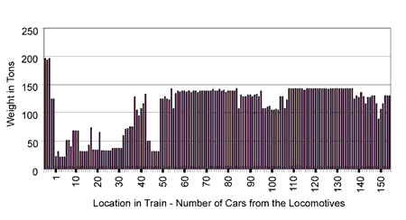
On 08 July 2003, train 442 had empty and lightly loaded cars totalling 2480 tons immediately behind the locomotive consist and ahead of loaded cars totalling 13 885 tons (see Figure 5).
- Locomotive with alignment control coupler is coupled against train.
- No two l
CN's train marshalling practice gave priority to the placement of cars in trains on the basis of their destination, commonly known as destination blocking. Cars destined to locations closest to the train's station of origin were generally marshalled closest to the locomotives to facilitate setting them out on line for operational expediency. Consistent with this practice, the two empty covered hopper cars on train 442 destined for Trochu, Alberta, were placed immediately behind the locomotives. The trailing 152 cars were destined for Calgary. The multi-platform cars were marshalled together on the head end of the train so the cars could be switched onto the Calgary Yard intermodal track upon arrival in the Calgary Yard.
1.12 Industry practices regarding train marshalling
An AAR study concluded in part that:
. . . the probability of undesirable Track/Train Dynamics occurrences can be reduced by placing the heavy cars closest to the motive power (regardless of its location) and the lighter cars farthest from the motive power.Footnote 12
CPR's GOI, Section 7, item 2.6, prescribes in part:
To reduce the probability of undesirable Track/Train Dynamics occurrences, the following marshalling instructions apply when practicable, subject to destination blocking:
- Heavy cars must be marshalled as close as possible to the head-end and light cars to the rear of trains.
- Large blocks of heavy cars must not be added to the rear of trains unless most cars ahead of the block are equally as heavy.
- Empty cars must not be added to the head end of large trains unless most of the cars behind such empty cars are either empty or have relatively light gross weight.
1.13 TSB Engineering Laboratory report
The TSB Engineering Laboratory examined the dynamic forces in this derailment (report LP 114/2002) and concluded, in part, that:
- The derailment resulted from a combination of large draw bar angles due to the non-alignment control coupler of the trailing locomotive, significantly high buff forces produced by high DB application, and the extremely light tare weight of the aluminum hopper car.
- The first car behind the locomotives derailed when it was rolled aside by the lateral force transformed from the buff forces produced by DB.
- The light tare weight (vertical) of the aluminum hopper car could not balance the transformed lateral force and the lateral/vertical (L/V) ratio reached the rollover criterion.
- The couplers between the trailing locomotive, CN 7271, and the first covered hopper car, CNWX 106549, were in a jackknifing position, which increased the transformed lateral force (see Figure 6).
- The contribution of the other isolated locomotive without alignment control couplers, CN 7036, immediately in front of the trailing locomotive, to the transformed lateral force on the first derailed covered hopper car was secondary.
The TSB Engineering Laboratory analysis also estimated that the angle at which the non-alignment control coupler at the trailing end of the trailing locomotive was in immediately before the derailment was between 9.2 degrees and 10.3 degrees. Under these conditions, the resultant transformed lateral force exceeded the derailment limiting criteria.
The couplers between the two trailing locomotives were in a jackknifing position but the vertical weight of the locomotives was sufficiently heavy so that the transformed lateral force would not exceed the derailment criteria (L/V ratio=0.82). The transformed lateral force resulted in the rail laterally rolling over when the force exceeded the track's lateral strength. The locomotives were much heavier and the L/V ratio for the locomotives was much less than the adjacent hopper car, which resulted in it derailing first. While this introduced a change of the draw bar angles at the other end of locomotive CN 7271, the change of draw bar angle was determined to be small so the jackknifing between the two locomotives could only have slightly changed the draw bar angles at the front of the first covered hopper car.
2.0 Analysis
The derailment occurred while train speed was being controlled by DB, when the locomotives were entering a curve while descending a grade. The train was marshalled such that two empty cars were coupled to a locomotive not equipped with alignment control couplers at the head end of a very heavy train. The condition of the track and rolling stock were not considered contributory to this accident. Therefore, the analysis will focus on the in-train forces, train operations and locomotive and train marshalling.
2.1 In-Train forces
As the train began to negotiate the curve with the slack between cars bunched by DB, longitudinal force began to be transformed into lateral force. The couplers between the trailing locomotive and the empty covered hopper car jackknifed. The transformation of longitudinal force to lateral force was exacerbated by the increased lateral swing of the non-alignment control coupler on the trailing locomotive and the jackknifed position taken by the couplers between the trailing locomotive and the covered hopper car. Although the couplers between the two trailing locomotives were also in a jackknifing position, this had only a small contribution to the overall transformed lateral force behind the locomotives. This lateral force was ultimately applied perpendicular to the rail at the wheel-rail interface, where it overcame the vertical force supplied by the weight of the rolling stock, and the derailment occurred.
The extent to which the lateral swing of the coupler without alignment control exceeded the maximum travel of an alignment control coupler was small; however, it significantly added to the transformation of lateral force. The couplers between the trailing locomotive and the first car were in a jackknifing position and the lateral movement of the non-alignment control coupler, between 9.2 degrees and 10.3 degrees, permitted the transformed lateral force to exceed the derailment criterion.
After the first covered hopper car rolled aside and the second covered hopper car derailed to the high side of the curve, the following cars rushed in and struck the trailing locomotive. Because DB was in use and of the emergency brake application initiated by the train separation, the longitudinal forces were further concentrated behind the locomotives. The rollover of the inner rail beneath the trailing locomotive either resulted from the jackknifing of the trailing locomotives at about the same time as the empty covered hopper car rolled aside or the impact force created when the train contacted the locomotives, or a combination of these events.
2.2 Train operations
The highest concentrations of longitudinal force occur behind the locomotives. The placement of the locomotives without alignment control couplers at the rear of the locomotive consist, next to empty cars, with limited capacity to absorb transformed lateral force, with very heavy tonnage behind, combined to create a weak link. This link was highly vulnerable to transformed lateral force, making the safe operation of the train difficult.
Railway GOIs conveyed the need for caution when making bunched stops and in particular when operating with locomotives not equipped with alignment control couplers. There was also a limitation placed on the amount of DB amperage to be generated while negotiating curves with high-horsepower locomotives. While it is uncertain that adherence to any specific instruction could have prevented this accident, it must be noted that the estimated DB amperage being developed as the train entered the curve exceeded the recommended amount significantly. Since DB amperage was not recorded on the type of locomotive event recorder that was on the lead locomotive, this could not be validated from the download. However, TSB Engineering Laboratory calculations indicate that the application was in excess of 20 per cent of the amount recommended by the railway.
Train 442 was the longest and heaviest that the crew operated on this subdivision. Even though the crew had undoubtedly operated trains that required extra caution in the past, they underestimated the danger posed by the combination of the locomotive without alignment control coupler, next to the empty cars with heavy tonnage behind, and they chose to use more than the recommended amount of DB.
2.3 Locomotive marshalling
Subsequent to the accident, CN issued an instruction restricting the number of locomotives without alignment control couplers in a train to one, when there are more than 4000 tons of trailing tonnage. While this is an improvement over existing guidelines, the investigation determined that the presence of more than one locomotive without alignment control couplers within the locomotive consist was secondary in this case. Rather, it was the placement of a locomotive without alignment control couplers in the trailing position in the locomotive consist that greatly increased the risk of derailment.
The AAR and some of its member railways suggest that locomotives without alignment control couplers not be placed in the trailing position of a locomotive consist. CN, on the other hand, has no restriction against the marshalling of locomotives without alignment control couplers in the trailing position in a locomotive consist and does not discourage this practice.
2.4 Train marshalling
For improved track-train dynamics, AAR guidelines recommend that heavy cars be marshalled close to the locomotives and empty cars be marshalled to the rear of the train. The majority of North American railways subscribe to this philosophy, subject to destination marshalling. Destination marshalling enables the railways to transport rail shipments in an expeditious manner.
Generally speaking, through experience and training, locomotive engineers can handle most trains in a manner that minimizes in-train forces. However, occasionally, there are circumstances in which the actions of a well-trained locomotive engineer cannot compensate for the latent unsafe condition created by destination train marshalling, and in the case of the occurrence train, the marshalling of the locomotive consist as well.
2.5 Locomotive event recorder
The train's locomotive event recorder indicated that the locomotives operated in DB, but it did not record the actual amount of DB that was being applied. Mandatory requirements to record such critical information as locomotive acceleration/deceleration, end-of-train brake pipe pressure, and the amount of DB applied would lead to more accurate analysis of rail occurrences and help in the timely determination of appropriate safety action to reduce risk.
3.0 Findings
3.1 Findings as to causes and contributing factors
- The derailment resulted when excessive transformed lateral force ejected a lightweight, empty covered hopper car from the train.
- The transformed lateral force exceeded the derailment criterion as a result of a number of factors acting in aggregate:
- the marshalling of a locomotive without alignment control couplers into the trailing position in the locomotive consist;
- the marshalling of an empty car at the front of the train;
- heavy trailing tonnage;
- the jackknifed position taken by the couplers between the rear of the trailing locomotive and the first car;
- a dynamic brake application in excess of the recommended intensity; and
- the negotiation of a curve by the front portion of the train during the dynamic brake application.
- The marshalling of train 442, solely on the basis of destination priority, created a latent unsafe condition that compromised safety on this occasion.
3.2 Findings as to risk
- The absence of constraints on placing empty/lightweight cars behind a locomotive consist and ahead of loaded cars presented an increased risk of derailment.
3.3 Other findings
- This particular locomotive event recorder did not record all critical information necessary to confirm the manner in which the train was operated preceding the occurrence, nor was it required to do so.
- The presence of the first locomotive without alignment control couplers behind the operating locomotives played a secondary role in this derailment.
4.0 Safety action
4.1 Action taken
On 10 July 2002, Canadian National (CN) issued Operating Bulletin 129, New Instruction: Yard Service Locomotives Handled on Trains (see Appendix A).
On 27 May 2003, Transport Canada (TC) began discussions with the Railway Association of Canada concerning the implementation of a train design system that would take train tonnage and train length into consideration. In addition, TC indicated that train handling instructions should be written as an aid to locomotive engineers.
On 29 July 2003, the TSB released report R99T0017 regarding the investigation into the passing of a signal indicating "STOP" by VIA Rail passenger train No. 52 at Trenton Junction Station in Trenton, Ontario, on 19 January 1999. As part of the report, the TSB issued Recommendation R03-02:
The Department of Transport, in conjunction with the railway industry, establish comprehensive national standards for locomotive data recorders that include a requirement for an on-board cab voice recording interfaced with on-board communications systems.
On 01 October 2003, TC responded as follows:
Transport Canada will work with the Canadian rail industry, the TSB and the Federal Railroad Administration (FRA), including the National Transportation Safety Board, to discuss and identify options and determine the advisability of the potential establishment of:
- comprehensive national standards addressing the survivability of Locomotive Event Recorders; and
- specifications for performance regarding the type of data recorded, which may include audio capabilities, and technological options available to the industry in order to interface with on-board communications systems.
Consultations with the FRA will also continue as harmonization with the U.S. regulatory requirements, whenever practicable, is important to facilitate the significant cross-border rail transport movements.
As a follow-up to TC's response to Recommendation R03-02, TC is currently finalizing the terms of reference to create a project team on the development of national standards for addressing the survivability of locomotive event recorders. The team will consist of representatives from TC, the Canadian rail industry and the U.S. FRA.
The scope of the project will be to identify options and provide advice on the potential establishment of comprehensive national standards and may include:
- identification of present regulatory requirements for locomotive event recorders, including survivability and specifications for the type of data recorded both in Canada in the U.S.;
- identification of the present and future regulatory requirements for event recorders, including audio capabilities, both in Canada and in the U. S.;
- identification of present and future technologies available to the industry with regards to locomotive event recorders, including survivability, type of data that can be recorded, audio capabilities and the interface with on-board communications systems;
- drafting of a final report identifying options and providing advice to TC and the rail industry on the potential establishment of comprehensive national standards for locomotive event recorders; and
- development of national safety standards on locomotive event recorders by the industry.
The project is expected to start in January 2004. A draft report will be prepared by September 2004 for review by the project team with an anticipated completion date of December 2004.
4.2 Safety concerns
The Board is concerned that CN's new policy of limiting the number of locomotives with non-alignment control couplers behind the operating locomotives in a train to one does not significantly reduce the risk of another similar derailment.
Furthermore, while some railways have chosen to use locomotive event recorders with enhanced capabilities, the federal requirements that established the use of these devices in Canada have not been updated to take advantage of additional safety-related data now available.
This report concludes the Transportation Safety Board's investigation into this occurrence. Consequently, the Board authorized the release of this report on .
Appendices
Appendix A - Canadian National's Operating Bulletin 129, New Instruction: Yard Service Locomotives Handled on Trains
Account a recent derailment involving the "jack-knifing" of two low-horsepower Yard Service locomotives that were marshalled behind the working consist on a heavy tonnage train utilizing Dynamic Brake, the following procedures are being implemented and are required:
- The following yard service locomotives are NOT equipped with alignment control couplers:
CN 1401-1402-1403-1404-1405-1406-1412
CN 4118-4119-4121-4122-4124-4125
CN 7024-7030-7036-7061-7073-7077-7078-7079-7080-7081-7082-7083
CN 7217-7236-7242-7271-237 (Slug)
GTW 4600-to-4635 - When any of the above locomotives are handled in train service behind the working locomotive consist AND trailing tonnage exceeds 4000 tons, it must not have any other locomotive identified in item 1) anywhere in the train behind the controlling locomotive. NOTE: This restriction does not apply when these identified locomotives are the working consist or are marshalled ahead of the working consist.
- Locomotive Engineers, when handling any of these identified locomotives in train service must utilize extra caution to protect against jack-knifing, especially when applying dynamic/independent brake while in motion or throttle when shoving against a cut of cars.
Please be governed accordingly. If in doubt as to any yard service locomotive restrictions herein listed, the MSREP [mechanical service representative] may be contacted for clarification.
