Main-track derailment
Canadian National
Freight train M-365-21-21
Mile 6.53, Lac-St-Jean Subdivision
Saint-Tite, Quebec
The Transportation Safety Board of Canada (TSB) investigated this occurrence for the purpose of advancing transportation safety. It is not the function of the Board to assign fault or determine civil or criminal liability. This report is not created for use in the context of legal, disciplinary or other proceedings. See Ownership and use of content. Masculine pronouns and position titles may be used to signify all genders to comply with the Canadian Transportation Accident Investigation and Safety Board Act (S.C. 1989, c. 3).
Summary
On 21 November 2009, at 2046 Eastern Standard Time, Canadian National train M-365-21-21 derailed 10 cars (5 loaded and 5 empty) on the railway bridge across des Envies River at Mile 6.53 of the Lac-St-Jean Subdivision, near Saint-Tite, Quebec. Approximately 200 feet of track was damaged and one span of the bridge was destroyed. The accident caused no injuries and no dangerous goods were released.
Ce rapport est également disponible en français.
Factual information
The accident
On 21 November 2009, Canadian National (CN) freight train M-365-21-21 (the train) was travelling south on the Lac-St-Jean Subdivision heading to Montréal, Quebec. The train consisted of 2 locomotives and 11 cars (5 loaded cars and 6 empty cars). It weighed about 1250 tons and was approximately 850 feet long. The crew consisted of a locomotive engineer and a conductor. They knew the area well, were qualified for their respective positions, and met fitness and rest standards.
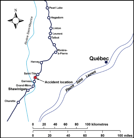
At 2046,Footnote 1 upon leaving Saint-Tite (see Figure 1), the train crew felt an unusual jarring as the train rolled over the railway bridge at des Envies River at Mile 6.53. Immediately afterwards, a train-initiated undesired emergency brake application occurred. The train was travelling at 38 mph and the throttle was in position 1. The lead locomotive came to rest about 1800 feet south of the bridge. After carrying out the required emergency procedures, the train crew determined that 10 cars (the 1st to the 10th) had derailed. One span of the railway bridge collapsed and three cars fell into the river. The sky was clear and the temperature was 2°C.
Particulars of the track
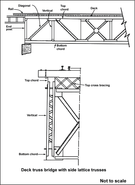
Southward from Saint-Tite, the track describes a 4-degree, 15-minute curve for a distance of 800 feet before crossing the des Envies River at Mile 6.53 on a steel deck truss bridge with open timber deck. The bridge consisted of two spans, with a combined length of about 160 feet, supported by two abutments and a central pier. The south span consisted of lattice girders and measured 111 feet in length, and the north span consisted of plate girders and was 50 feet in length.
The track consisted of 115-pound continuous welded rail (CWR) laid on double-shouldered tie plates secured with three spikes per tie. There were approximately 3200 hardwood ties per mile. The rail was box-anchored every tie. The ballast consisted mainly of crushed rock, was in good condition and showed no signs of fouling. The cribs were full and the shoulders were about 18 inches wide.
Site examination
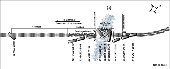
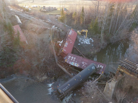
The derailed rolling stock consisted of five loaded box cars and five empty tank cars (see Figure 2). No wheel marks or dragging equipment marks were observed to the north of the bridge. Near the south bridge abutment, wheel flange marks were observed on the tops of the ties and on the tie plates. These marks extended over a distance of 1600 feet southward and ended at the trailing truck of the first derailed car, box car TBOX665577. This car remained coupled to the forward part of the train with the trailing truck derailed on the east side of the track. The next three cars descended the embankment and came to rest in the ditch on the east side of the track near the south bridge abutment. The 5th, 6th and 7th cars came to rest on the trusses of the south span that had collapsed into the river bed (see Photo 1). The other derailed cars were on the north side of the river.
The primary and secondary steel members of the south span were twisted, wheel flange marks and scrapes were visible on the top of the top chord, and several rivet heads were sheared off (see Appendix A). The deck ties were broken up; however, the wood fibres in the tie fragments showed no signs of deterioration or rot. The south abutment backwall was struck by the right front and the coupler of the 5th car and broke into several pieces.
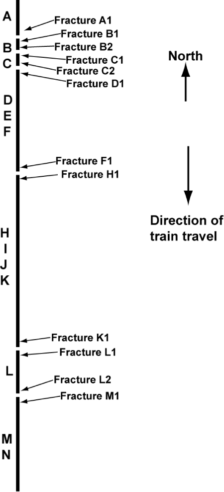
All derailed rolling stock and the steel members of the south span were examined; no pre-derailment defects were found. Over 30 pieces of broken rail were recovered and sent to the TSB Laboratory, where a section of about 130 linear feet of rail was reconstructed (see Appendices B and C). Piece A, from the east rail, had remained fastened to the ties. Its end, which was projecting 18 inches beyond the end of the north span above the central bridge pier, was fractured and pounded downwards. Piece B, 3 feet 10 inches in length, was found near the central pier, buried under the bottom chord of the collapsed span.
Track information
The Lac-St-Jean Subdivision consists of a single main track extending from the Garneau Yard near Grand-Mère, Quebec (Mile 0.0) to Arvida, Quebec (Mile 203.5). Train movements are governed by the Occupancy Control System authorized under the Canadian Rail Operating Rules and supervised by a rail traffic controller located in Montréal. The track is Class 3 as defined in the Transport Canada-approved Railway Track Safety Rules (TSR). In the accident area, the maximum authorized speed is 40 mph for freight trains and 45 mph for passenger trains. Rail traffic on this secondary line is four to seven freight trains and one passenger train per day, representing an annual tonnage of approximately 12 million gross tons (MGT).
Inspections
The train had passed several wayside inspection systems (WISs) and did not trip any alarms. The wheel impact load detector (WILD) at Mile 7.7, less than two miles north of the accident site, recorded no readings that exceeded CN's impact load limit on train M-365-21-21 or the three previous trains.
In 2009, all inspections were completed on the Lac-St-Jean Subdivision in accordance with the TSR. Two inspections were made using a track geometry test car. The most recent inspection, on 15 October 2009, found no defects in the Saint-Tite area.
There were 27 regular track inspections carried out with a hi-rail vehicle in the three months preceding the derailment. The last one was on 19 November 2009, and no exceptions were noted in the derailment area.
The steel structure and deck of the bridge were inspected regularly, and the last visual inspection was performed on 11 November 2009. No exceptions were noted. Maintenance was carried out on the bridge periodically. When repairs were last done in 2002, the bridge capacity was increased to allow 286 000-pound cars to cross without restrictions.
Rail inspection
Five continuous track inspections for internal rail defects were conducted in 2009 using a vehicle equipped with transducers, an ultrasonic signal generator, a signal processor and a host computer (see Appendix D). The system can detect internal defects of less than ½ inch in the rail head and web. Defects are recognized, classified and measured by software. This advanced technology sorts the signals received and helps the operator interpret the data. No defects were found in the derailment area on the last ultrasonic inspection conducted on 12 November 2009.
Ultrasonic inspection is the primary method used to detect internal rail defects and control the risk of rail failures. Over the years, improvements have been made in the field of rail testing, including operator training, additional probes positioned at different angles, and improvements to defect recognition software. This has proven to be a reliable and economical testing method. However, detail fractures cannot in some cases be detected due to their orientation with the surface of the rail or because they are masked by shell cracks above the detail fracture.
After a derailment in British Columbia (TSB investigation report R06C0104), CN required that rail ultrasonic inspections be conducted at a speed not exceeding 5 mph on bridges over 100 feet in length and bridges over a road or navigable waterway, and that all imperfections detected by the system be identified by the operator by means of an icon or explanation. In addition, all defects identifying a crack or welding defect must be examined visually or verified with a hand-held device. Records indicate that the east rail on the bridge transmitted a signal that was attributed to the condition of the rail surface and was not verified with a hand-held device.
The rail
CN's Standard Practice Circular (SPC) 3200 issued in April 2005, which was in effect when the 115-pound rail was laid on the Saint-Tite bridge, provided instructions regarding rail use and rail wear.
In 2006, the rail in the curve to the north of the bridge was replaced with a new rail. The Sydney 1976 rail that was recovered was reclassified and, subsequently, a 190-foot plug was used to replace the jointed east rail on the bridge, which was of lower quality. It is common practice and consistent with sound asset management to re-use certain rails. Vertical wear was measured at 10 to 13 mm with negligible lateral wear. The combined total of these two wear measurements is under the limit of 21 mm for 115-pound rail. The running surface of the rail showed signs of cracking and shelling at the gauge corner.
Grinding
CN grinds its rails to remove fatigue cracks, head cracks and shelling at the gauge corner. Dressing out the wheel-to-rail contact surface limits the initiation and propagation of rail defects. The last time the rail in the curve to the north of the bridge was ground was in 2005.
Rail grinding on the Lac-St-Jean Subdivision, except on the des Envies River bridge, was done in July 2007. Rails in the adjacent curves were ground again in July 2008.
Rail laboratory analysis
The TSB Laboratory did a detailed visual examination of the rail pieces recovered to characterize the fracture surfaces and document the number, size and locations of transverse defects. Most of the fractures had a coarse, granular appearance with chevron markings and tear ridges, which is consistent with overstress fracture caused by the derailment.
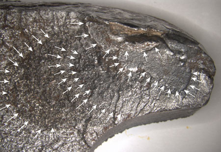
However, the pieces identified as A1Footnote 2 and B1 showed different indicators. Both fracture surfaces had regions near their gauge corners that had a thumbnail-shaped contour suggestive of pre-existing fatigue cracking. The pre-existing cracking on fracture surface A1 was only 4.5 mm long, while that on fracture surface B1 extended across approximately 40 per cent of the total head area. Fracture B1 exhibited multiple crack arrest lines, with progressively less corrosion and a rougher surface topography further away from the gauge corner. Examination with a scanning electron microscope (SEM) at different points in the progressive fracture region revealed transgranular cleavage, which indicates rapid crack growth, together with smooth areas indicating slow crack growth. This indicates a varying rate of crack growth (see Photo 2). The fracture surface in the last region of progressive growth, which immediately preceded the final failure in overload, shows transgranular cleavage indicating that the last phase of progressive growth was relatively rapid.
The rail running surface in the vicinity of fractures A1 and B1 suggests a shelling problem. Shell cracks form under and parallel to the running surface of a rail. They are a type of rolling contact fatigue caused primarily by the heavy pressure of the wheelsFootnote 3 on the rail, and tend to be located at the more heavily loaded regions of the rail such as near the gauge corner.
When a shell develops near the surface of a rail and grows sufficiently long, it will cause a small piece of the surface to break away, resulting in spalling of the rail. In some cases, however, a crack will develop from the shell and propagate perpendicular to the running surface through the head of a rail, resulting in a fatigue crack.
Progressive transverse defects initiated at surface
Transverse defects are among the group of defects caused by fatigue. They are progressive failures resulting from a longitudinal separation near the running surface or from a shell crack that starts at the gauge corner and progresses crosswise in the rail head. They are caused by high rail traffic volume and loading. A fracture can develop in any rail, but it progresses usually in older rails, especially in the absence of lubrication or grinding.
Shelling and surface microcracking in a rail head are surface fatigue defects caused by the stresses applied by train traffic and by inadequate wheel-to-rail contact geometry. Once initiated, shell cracks can propagate to some length.
Crack propagation is unpredictable and relatively slow from initiation until it reaches 10 per cent of the rail head surface, but from that point, it can advance rapidly. Ultrasonic inspection is the only way they can be detected before the rail fractures.
The age of the Sydney 1976 east rail, which was taken from the curve to the north of the bridge, suggests that it was in service for a long time. The accumulated tonnage on the rail is unknown. The rail had not reached its wear limit, but it can also fail in fatigue. The development of cracks caused by fatigue depends on a combination of factors such as accumulated tonnage, location (curve or tangent), cleanliness and classification of the steel, condition of the track structure, and rail maintenance. Fatigue cracks can be detected only by inspections designed to detect internal rail defects, and the Sydney 1976 rail was inspected many times, both in the curve and on the bridge, since it was first laid.
Rate of growth of progressive transverse defects
The three factors that have the greatest effect on the rate of progression of transverse defects are the difference between the current temperature of the rail and the neutral temperature at which the rail was laidFootnote 4; residual stressesFootnote 5 in the overall section of rail whether in tension or in compression; and the degree of curvature, since the greater lateral stresses that are experienced in a curve generate greater cyclic loads due to wheel contact.
Analysis
It was established that neither the condition of the rolling stock or track structure nor the operation of the train contributed to the accident. Defects were found in at least one piece of rail recovered at the derailment site. The analysis will focus on rail defects, rail management, the interpretation of standards and track inspection.
The accident
The train derailed following a rail failure as the train was crossing the bridge. The running surfaces of the pieces of rail identified indicate that the train derailed just south of the central bridge pier. The broken rail and the destruction of the deck by wheel impact prevented the train from staying level on the rails. Since the train rolled over onto the top chord of the steel structure and that structure was being pushed at the same time, the bridge tipped sideways and collapsed due to the lateral stresses generated by the derailed cars. The bridge deck and steel structure failed due to the impact forces generated by the derailed rolling stock.
The pre-existing defects found on the fracture surface were fatigue defects called transverse defects. These defects originated as sub-surface shell cracks that propagated longitudinally in the rail. The sub-surface shell cracks are also transverse defects resulting from repeated wheel contact loading. Once formed, transverse defects continue to progress and eventually reduce the capacity of the rail to withstand the loads applied by the wheels. Progression of the defect reduced the bearing strength of the rail to the point where it could not bear the train loads, and the rail failed.
When the train was crossing the bridge, abnormal jarring was felt. The train struck the failed rail, and the cracks propagated as a result of overloading and caused the rail to fracture in several pieces. This broadened the gap to the point where the wheels left the running surface and rolled onto the bridge deck.
Examination revealed that surface B1 had a large pre-existing transverse defect extending from the gauge corner approximately halfway through the head. This transverse defect initiated at a sub-surface crack and propagated by fatigue downwards in the head. The defect grew at different rates since its initiation. It was not possible to measure these rates of growth, but the combination of characteristics indicating rapid and slow rates suggests that the growth rate of the defect was not stable. Since the characteristics of the last region of progressive growth indicate rapid growth, it is possible that this defect grew rapidly after the last inspection for internal rail defects, and that it was much smaller at the time of the last inspection.
Rail management
Replacing jointed rail with CWR to eliminate impact loads and doing maintenance on rail joints is common practice and indicates economical utilization of assets. Although the CWR laid on the bridge in 2006 was an improvement over the jointed rail, it is not desirable to use relay rail with surface shelling on a critical structure such as a bridge.
Although the rail taken from the curve was considered satisfactory for re-use, the defects in formation were not ground out before it was relaid on the bridge. This contributed to the growth of existing defects and the development of new transverse defects and shelling in the head of the relaid east rail, distorting the results of the inspection for internal rail defects on 12 November 2009.
The existing defects were masked by the poor condition of the running surface. The ultrasonic waves were diffused and reflected, preventing proper identification of internal rail defects.
CN's SPC 3200 would have required that all new and relay rail laid on a main track be 136-pound fully head-hardened (FHH) rail conforming to the specifications for clean steel. However, the only requirement that CN stipulated for the selection of rails for spot replacements was that the wear and profile of the rail be similar to those of the rails in place. The use of unground relay rail on a critical structure such as a bridge increases the risk of unidentified defects propagating to the point of failure.
Track inspection
Detailed track inspections were conducted regularly by experienced engineering department inspectors, resulting in the identification and correction of several defects on the Lac-St-Jean Subdivision. However, transverse defects that progress under the surface of the rail can only be detected by inspecting with a vehicle equipped to detect internal rail defects. Despite frequent inspections, and because they are not always visible, these pre-existing defects can grow rapidly to a critical size in an uncontrolled manner.
Although the inspection for internal rail defects on 12 November 2009 on the section of track that includes the Saint-Tite bridge was done at the correct speed, all the imperfections noted on the rail were attributed to the condition of the running surface (splinters, creep/shelling, dirt/grease) and were not examined or verified with a hand-held device. Since these imperfections were not verified with a hand-held device, the opportunity to confirm a defect was lost.
In 2007, Sperry Rail Service introduced a new X-Fire (crossfire) probe developed to improve detection of under shell defects in the gauge corner area of the rail. Software is used to recognize, classify and measure the defects. This advanced technology sorts the signals received and helps the operator interpret the data. The new technology allows more accurate and faster inspections and identifies defects that were not correctly interpreted in the past. When the inspection vehicle is not fitted with the new X-Fire probe, there is a greater risk that internal rail defects and fatigue cracks in the gauge corner area may not be identified effectively below shelling.
The following TSB Laboratory report was completed:
LP 169/2009 – Rail Examination
This report is available from the Transportation Safety Board of Canada upon request.
Findings
Findings as to causes and contributing factors
- The train derailed following a rail failure as the train was crossing the bridge. The bridge deck and steel structure failed due to impact forces from the derailed rolling stock.
- The rail had not been ground since 2005. In the absence of rail grinding, the growth of existing defects and the development of new transverse defects and shelling were not slowed down.
- Progression of the existing defect reduced the bearing strength of the rail to the point where it could not bear the train loads.
- The existing defects were masked by the poor condition of the running surface. The ultrasonic waves were diffused and reflected, preventing proper identification of internal rail defects.
- Although the inspection was done at the correct speed, all the imperfections noted on the rail were attributed to the condition of the running surface and were not examined or verified with a hand-held device.
Findings as to risk
- The use of unground relay rail on a critical structure such as a bridge increases the risk of unidentified defects propagating to the point of failure.
- When the inspection vehicle is not fitted with the new X-Fire probe, there is a greater risk that internal rail defects and fatigue cracks in the gauge corner area may not be identified effectively below shelling.
Other findings
- Since the characteristics of the last region of progressive growth indicate rapid growth, it is possible that this defect grew rapidly after the last inspection for internal rail defects, and that it was much smaller at the time of the last inspection.
- Despite frequent inspections, and because they are not always visible, these pre-existing defects can grow rapidly to a critical size in an uncontrolled manner.
This report concludes the Transportation Safety Board's investigation into this occurrence. Consequently, the Board authorized the release of this report on .
Appendices
Appendix A – Railway bridge sketch
Appendix B – Nomenclature of rail pieces recovered
Appendix C – Rail pieces recovered
| Rail Piece | Length (inches) | Markings and Notes |
|---|---|---|
| A | 119 | 11501 SYDNEY VT 115 LBS RE 1976 II CC 68665 23 D |
| B | 39 | 501 SYDNEY VT 115 LBS RE 1976 II 665 23 D |
| C | 38 | II |
| D | 106 | 11501 SYDNEY VT 115 LBS RE 1976 II 68666 23 C |
| E | 127 | Piece contains a weld Section 1 - 115 LBS RE 1976 II Section 2 - No markings |
| F, G | 125 | 115 RE SYDNEY 1994 IIIIIIIII 04 VT 3HB 47544 P2 |
| H | 151 | 115 RE CC BSCo LACKAWANNA 1954 IIII A1 |
| I | 144 | 115 RE CC BSCo LACKAWANNA 1954 IIII |
| J | 144 | Piece contains a weld Section 1 - 11501 SYDNEY VT 115 LBS RE 1976 II 68666-23 C Section 2 - 991190 |
| K | 86 | 11501 SYDNEY VT 115 LBS RE 1976 II 68666 23 C |
| L | 152 | 115 RE SYDNEY 1994 IIIIIIIII 3HB 47544 P2 |
| M | 110 | CC BS Co LACKAWANNA 1954 IIII 921190 D 13 |
| N | 95 | Piece contains 2 welds Section 1 - S Co LACKAWANNA 195 Section 2 - T-115 LBS RE 1976 IIII Section 3 - No markings |
Appendix D – Rail inspections
The basic rail flaw testing system consists of a test vehicle equipped with ultrasonic probes, an ultrasonic signal generation unit, a signal processing unit and a host computer. All testing parameters are calculated in real time and can be analyzed either on board the rail vehicle or during post-test processing activities. Testing for internal rail defects on Canadian National (CN) is performed by various contractors. Its fleet of hi-rail vehicles is equipped with state-of-the-art ultrasonic detection equipment that provides real-time analysis of the rail section. The test vehicles are equipped to operate in the extreme climatic conditions that are common throughout North America.
Rail flaw testing has been steadily enhanced to reduce accidents caused by rail defects but still has limitations, and a 100 per cent accuracy rate is beyond current equipment capability. Testing accuracy remains dependent on the skill, training, and experience of the operators to properly interpret data and identify defects. Testing accuracy is also affected by rail conditions because grease or dirt on the rail head, head checking and internal shelling can interfere with the ultrasonic signal. Defects must be large enough and oriented so that they present a reflective surface large enough to be detected.
