Main-track derailment
Canadian Pacific Railway
Freight train 2-269-02
Mile 21.4, Red Deer Subdivision
Airdrie, Alberta
The Transportation Safety Board of Canada (TSB) investigated this occurrence for the purpose of advancing transportation safety. It is not the function of the Board to assign fault or determine civil or criminal liability. This report is not created for use in the context of legal, disciplinary or other proceedings. See Ownership and use of content. Masculine pronouns and position titles may be used to signify all genders to comply with the Canadian Transportation Accident Investigation and Safety Board Act (S.C. 1989, c. 3).
Summary
On 03 August 2010, at 0643 Mountain Daylight Time, Canadian Pacific Railway freight train 2-269-02, proceeding southward from Red Deer, Alberta to Calgary, Alberta, derailed 32 cars at Mile 21.4 of the Red Deer Subdivision near Airdrie, Alberta. The derailed cars included 12 pressure tank cars containing anhydrous ammonia (UN 1005). No product was lost and there were no injuries.
Ce rapport est également disponible en français.
Factual information
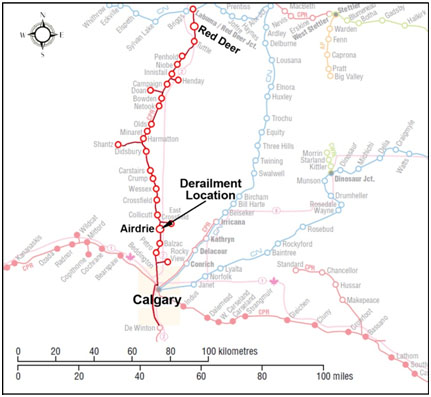
Canadian Pacific Railway (CP) freight train 2-269-02 (the train) consisted of 2 General Electric AC 4400 operating locomotives, 82 loads and 19 empties. It weighed 10,786 tons and was 6311 feet long. No irregularities or problems with the train were noted between Red Deer and Airdrie, Alberta (see Figure 1).
The train crew, a locomotive engineer and a conductor, took control of the train in Red Deer, Alberta. They met fitness and rest standards and were qualified to operate trains on the Red Deer Subdivision.Footnote 1
Recorded information indicates that the train was travelling at 35.8 mph when a train-initiated emergency brake application occurred at 0643:47.Footnote 2 An emergency brake application was initiated 2 seconds later at the rear of the train by the Sense and Braking Unit (SBU) of the train information braking system (TIBS) when the locomotive engineer placed the brake handle into emergency.
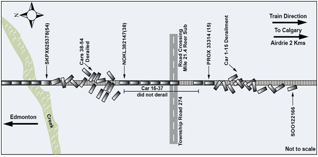
After making the necessary emergency broadcast and notifying the rail traffic controller (RTC), the conductor performed an inspection and determined that 15 cars, the 1st to 15th, had derailed behind the locomotives. Knowing that dangerous goods cars were marshalled near the head end (i.e., 27 of the 1st 30 cars contained anhydrous ammonia, UN 1005),Footnote 3 the crew moved the locomotives southward to a safe location. Further inspection revealed that another 17 cars, the 38th to 54th, had derailed towards the middle of the train near Mile 21.7 (see Figure 2). There were no injuries, no dangerous goods were released and no product was lost.
Weather
The weather was clear with unlimited visibility and the temperature was 8°C.
Incident response
The derailment occurred approximately 2 kilometers north of Airdrie, a city of 40,000 people north of Calgary. CP and Alberta Environment responded to the accident. CANUTEC,Footnote 4 Airdrie Fire Department, Rocky View County Fire Services and Calgary Fire Department (Hazmat Branch) also responded. Representatives from Agrium, the shipper of the anhydrous ammonia, and the Alberta Emergency Management Agency (AEMA) were also present at the derailment site. AEMA is responsible for the co-ordination of all organizations involved in the prevention, preparedness and response to disasters and emergencies in the Province of Alberta. At this accident site, the Incident Command System was initially established by the Airdrie Fire Department in conjunction with Rocky View County Fire Services. AEMA provided assistance with operating the Incident Command Center during the response.
Access to the area of the south derailment (i.e., towards the head end) was restricted to emergency responders only. An evacuation of 3 farms and 12 people within a 1⁄4 mile of the site was ordered until a risk assessment determined that no tank cars had been breached or were leaking. The evacuation was lifted 4 days later (07 August 2010) following the completion of the transhipment of anhydrous ammonia from the derailed tank cars.
The City of Airdrie Emergency Operations Center (EOC) coordinated the emergency evacuation plans in the event of a leak during the transhipment of product. An urgent care center was set up in Airdrie close to the EOC. Through public service announcements, residents were advised of the procedures in the event of an emergency.
Rolling stock
The 15 derailed cars immediately behind the locomotives included 1 loaded hopper of grain, 2 loaded hoppers of plastic pellets and 12 pressure tank cars containing anhydrous ammonia. The 2nd group of 17 derailed cars included 6 loaded hopper cars of grain, 3 empty steel coil covered gondolas and 8 empty flat cars. Examination of the derailed rolling stock found no evidence that the condition of the cars contributed to the derailment.
A review of records from the hot box detector (HBD) at Mile 22.7 showed no exceptions. Information from the wheel impact load detector (WILD) at Mile 22.8, for the derailed train and the 2 previous trains over the accident site, did not indicate any impacts exceeding CP's threshold for removal.Footnote 5
Train information
Train 2-269-02 departed Edmonton with light engines. At Wetaskiwin, the train lifted 53 loaded grain cars and 1 empty car. On arrival at Red Deer, another 29 loaded cars and 18 empty cars were lifted and placed behind the 1st car on the train to provide a buffer between the locomotives and the anhydrous ammonia cars.Footnote 6 The 1st car behind the 2 locomotives was a loaded grain hopper car. The 2nd to 30th cars included 2 covered hopper cars loaded with plastic pellets followed by 27 loaded tank cars containing anhydrous ammonia. The next group of 18 cars, the 31st to 48th, comprised 8 empty gondola cars and 10 empty covered steel coil flat cars, all with cushioned drawbars.
The main design objective of cushioned drawbar systems is to reduce and cushion the buff forces during coupling in yards on rail cars that carry sensitive lading (such as automobiles). Rail cars so equipped can actually lead to higher in-train forces during transit because of the greater available slack, especially when grouped in large numbers and when there is a heavy block of cars with standard draft gear right behind them.
CP has developed special requirements in the Train Area Marshalling system (TrAM) for cars with cushioned drawbar systems.The occurrence train had no TrAM cushion drawbar restrictions (CP General Operating Instructions Section 7, 5.2, 5.3).
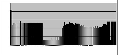
The 49th to 101st cars were loaded grain hopper cars, except for the 96th car, which was an empty grain hopper car. The tonnage profile for the train is included (see Figure 3).
Train marshalling
Canadian Pacific Railway has developed and implemented a proprietary system called Train Area Marshalling (TrAM) to help marshall trains in a manner which minimizes in-train buff and draft forces when operating on main track under normal train handling conditions. TrAM is computer-supported and includes territory-specific instructions regarding marshalling and trailing tonnage limits for specific types of car equipment. The limits vary depending on the type, length, and weight (i.e., content plus empty car weight) of the car, the length of the adjacent car, as well as, curvature and grade of the track over which the train will operate.
The train was classified as a mixed conventional trainFootnote 7 according to CP General Operating Instructions (GOI) Section 7, 2.3. CP GOI Section 7, 6.1 requires that mixed conventional freight trains be made up, to the maximum extent practicable, with the loads located closest to the locomotives. Heavy blocks of cars are not marshalled at the rear of the train unless blocks ahead are equally as heavy. Light cars (empties) or blocks of light cars are to be marshalled as close as possible to the rear unless the cars behind are also relatively light.
CP's network is divided into 6 TrAM areas. The Red Deer Subdivision is categorized as TrAM Area 1. Despite having a group of 18 empty cars marshalled ahead of the loaded grain hopper cars, the occurrence train had no reported TrAM Area 1 violations. TrAM is designed to keep in-train forces in check when train handling and other relevant inputs are maintained within the normal operating range. As such, TrAM may reduce, but is not designed to fully mitigate, the extraordinary in-train forces that can be generated during a derailment or during an emergency brake application.
Subdivision information
The method of train control on the Red Deer Subdivision is the Occupancy Control System (OCS), authorized by the Canadian Rail Operating Rules (CROR) and supervised by a rail traffic controller (RTC) in Calgary. The maximum speed for freight trains is 45 mph. The Red Deer Subdivision is Class 4 trackFootnote 8 as defined by the Railway Track Safety Rules (TSR).Footnote 9 In 2009, the line carried 28.6 million gross tons (MGT) of traffic. The total accumulated tonnage since 1983 is estimated to be 540 MGT.
Particulars of the track
The derailment occurred on tangent track south of a farm crossing at Mile 21.4 on a 0.6 % ascending grade. The Point Of Derailment (POD) for the 1st group of derailed cars was located approximately 20 feet south of this crossing.
The track is continuous welded rail (CWR). The west rail is 1982 115 pounds RE Algoma and the east rail is 1981 115 pounds RE Algoma. Most of the rail on the Red Deer Subdivision is 1981 to 1985 Algoma standard carbon rail. The rails were laid on 14–inch double shoulder tie plates and fixed with 3 spikes per plate on treated hardwood ties. The west rail was box anchored every other tie and the east rail was box anchored every tie. The ballast, subgrade and drainage were in good condition.
Track inspection and maintenance
The track was inspected by a certified track inspector with a hi-rail vehicle on 30 July 2010. No defects were noted in the vicinity of the derailment. The last maintenance work performed in the area was hand surfacing completed on 23 July 2010 on the west rail at Mile 21.7 and at Mile 21.4.
CP's track evaluation car (TEC) conducted geometry tests on the Red Deer Subdivision on April 16 and July 06. For the April 16 test, there were no urgentFootnote 10 defects between Mile 19.6 and Mile 23.0. However, in the vicinity of Mile 21.4, there were a number of priorityFootnote 11 defects including 4 S22 (Surface 22 feet) defects, 1 S62 (Surface 62 feet) defect and 2 R31 (Runoff 31 feet) profile defects on the west rail, as well as, 1 RC20 (Rate of Change Over 20 feet) defect and 4 RC62 (Rate of Change Over 62 feet) cross level defects.
For the July 06 2010 TEC test, there were 2 urgent R31 defects noted on the west rail in the vicinity of Mile 21.4. The 06 July 2010 test also recorded 4 S22 defects, 1 S62 defect and 4 R31 priority profile defects on the west rail, 1 RC20 defect and 1 RC62 priority cross level defect at Mile 21.4. These defects were protected with a 40 mph temporary slow order until they were repaired.
For Class 4 track:
- An urgent R31 defect occurs when the runoff (elevation difference) in the rail surface measured over 31 feet exceeds 1½ inches.
- A priority S22 defect occurs when the measured vertical displacement or midpoint of a 22-foot chord strung along the top of the rail exceeds 5⁄8 inch. S22 defects are commonly associated with joints and may cause high impacts, resulting in rail or track failure.
- A priority S62 defect occurs when the measured vertical displacement or midpoint of a 62-foot chord exceeds 1-1⁄8 inch.
- A priority RC20 defect occurs when cross level (difference in elevation between the 2 rails) measurements taken 20 feet apart differ by more than 7⁄8 inch. This defect uses a 20-foot baseline because it corresponds to the 1⁄2 length of a 39-foot rail and is used specifically to find low joints.
- A priority RC62 defect occurs when the difference (in elevation between the 2 rails) between any 2 points less than 62 feet apart exceeds 1 inch.
- An R31 priority defect occurs when the measured runoff over 31 feet exceeds 1 inch. Runoff defects may be found off road crossings and usually occur on only one rail.
Recorded information
LocoCAMFootnote 12 downloads of the last 3 trains over the derailment site, including the derailed train, captured images and audible signatures of an irregularity on the west rail south of the farm crossing.
Laboratory analysis of broken rail
Twelve pieces of broken rail were recovered from the area of the 1st POD (Mile 21.4). The rail pieces were examined at CP's Test Department in Winnipeg in the presence of TSB investigators. Visual, macroscopic and metallographic inspections were performed. In addition, chemical analysis and hardness testing were conducted. The rail's chemical composition and hardness were determined to be typical for plain carbon steel rail. There was no visible evidence of any material, manufacturing and/or metallurgical defects in the rail.
A total of 825 inches (68 feet- 9 inches) of rail (358 inches of the east rail and 467 inches of the west rail) was subject to failure analysis. Both rails had vertical wear and gauge wear of approximately 3⁄32 inches and 5⁄16 inches, respectively. This amount of rail wear is under the line A wear limit for 115-pound rail (ref.: CP's Red Book of Track Requirements dated May 15, 2010; Section 17).
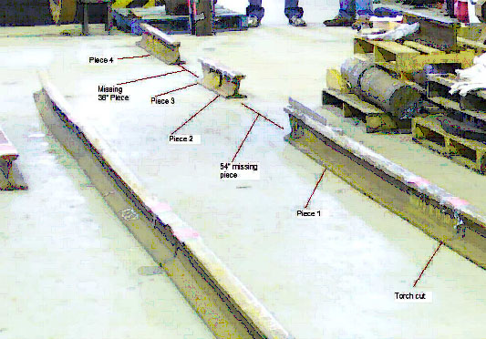
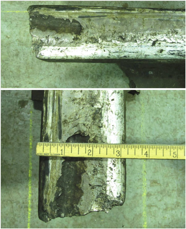
The 467 inch long section of the west rail consisted of 6 recovered pieces and 2 voids (see Photo 1). From north to south, there were 3 mating pieces (including Piece 1) measuring 272 inches long followed by a void of 54 inches. Then, 2 mating pieces 44 inches long (Pieces 2 and 3), another void measuring 36 inches long and then a piece of rail 61 inches long (Piece 4). The 3 pieces recovered south of the 1st void (i.e., Pieces 2, 3 and 4) and the POD displayed batter consistent with the train's direction of travel.
The running surface at the south end of the 3 mating pieces showed material flow and heavy checking on the gauge corner. A 10 inch long section of rail head was crushed, measuring approximately 7⁄16 inches at it deepest point. Corresponding shelling was also observed on the running surface at the fractured south end (see Photos 2 and Photo 3). This fracture surface revealed a crystalline texture typical of a catastrophic 2nd failure. The width of the rail head at the fracture was 3- 3⁄16 inches compared to a width of 2- 7⁄8 inches, approximately 12 inches away.
CP's Red Book of Track Requirements, Section 16.4.4, defines 2 types of crushed head defects. A crushed head defect is classified as CRO (crushed rail head) when the rail surface is flattened out ¼ inches or greater at the lowest point. For CRO defects, trains are restricted to 40 mph. Crushed head defects are not considered serious defects, but are generally removed from track because they can cause rough riding of rolling stock and are points of concentrated loading that may develop additional defects.
Rail grinding
CP performs rail grinding to remove surface fatigue cracking and head checking and to keep the wheel contact band within the centre of the rail head, reducing the initiation and growth of rail defects. The last production grind on the Red Deer Subdivision occurred between 12 and 14 August 2009. Production grinders lift their grinding motors as they approach a crossing and do not grind rail through crossings due to the planks. A switch and crossing grinder was scheduled for such work at this location in 2011.
When rail is not ground, it can lead to the development of surface and internal defects. TSB's investigation into the CP derailment at Mile 45.62 Taber Subdivision on 30 November 2008 (R08C0164) determined that the failure to spot-grind the poor rail surface condition through a crossing likely prevented the detection of internal detail fracture defects that led to the rail breaking under the train and derailment.
Rail testing
Ultrasonic inspection is the primary method used to detect internal rail defects and to control the risk of rail failures. In recent years, improvements have been made in the field of rail testing, including operator training, additional probes positioned at different angles, and improvements to the defect-recognition software. Ultrasonic testing has proven to be a reliable and economical testing method, but with limitations. The detectability of defects is dependent on the size and orientation of the transverse component and can be influenced by rail surface conditions such as the presence of grease or dirt on the rail head. Other factors such as head checking and internal shelling can also affect the test results.
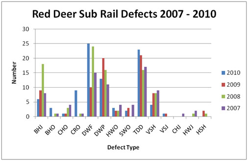
The Railway Track Safety Rules require Class 4 track to be inspected for internal defects at least once per year. However, according to CP's Standard Practice Circular (SPC) 27, Rail Testing Frequency and Remedial Action for Defective Rails, the Red Deer Subdivision would have required 2 tests per year. For this track, the frequency of inspections exceeded the TSR and SPC requirements.Footnote 13 Test records indicate that there were 3 ultrasonic rail tests conducted on the Red Deer Subdivision prior to the derailment, with a total of 6 tests performed in 2010. Appendix A summarizes the results of the past 4 years of rail defect testing on the Red Deer Subdivision. There were no in-service rail failures and no rail defects detected in the vicinity of the derailment by the tests performed prior to the derailment.
The rail through the area of the derailment was last tested 07 June 2010 by Sperry Rail Services (SRS) Car 965, which is equipped with the latest operator analysis tools and ultrasonic and induction testing technology (see Appendix B). The test results showed that there were equipment responses approximately 20 feet south of the crossing in the vicinity of the POD. During this test, the operator attributed the ultrasonic response to rail surface condition and not to a rail defect. The test vehicle was not stopped to perform a hand test.
After the occurrence, the 07 June 2010 test results were re-evaluated in conjunction with SRS. It was determined that the equipment responses showed typical characteristics indicative of a rail surface condition and was not significantly different from the condition of the rail in the general vicinity. This verification corresponds with the operator's interpretation of the test results and the decision not to conduct a hand test.
SRS Test vehicle operators undergo comprehensive training programs with respect to company procedures and rail testing protocols. However, during the 07 June 2010 test, the crossing was not noted on the test tape. In addition, the test speed (13.8 mph) over the crossing was in excess of the 7 – 8 mph crossing restriction.
Train air brakes
The train air brake system consists of mechanical rigging and air brake components which are operated by compressed air from the locomotive.
CP's operating air brake pressure is 90 psi. During a normal or service brake application, brake pipe pressure is reduced at a slow, controlled rate. The reduced air pressure causes the control air flow valve to operate and allow air to flow from the auxiliary reservoir through the control valve. The air pressure causes the brake cylinder to operate which in turn causes the brake rigging to move and the brakes shoes to apply against the wheel treads.
Brake pipe pressure is reduced more rapidly during an emergency application than during a normal brake application. This faster rate of drop in brake pipe pressure in the control valve allows air from both the emergency and auxiliary reservoirs to flow to the brake cylinder, thus causing the brakes to apply at a faster rate and with greater braking force. CP uses an SBU at the rear of trains that responds to both service and operator initiated emergency brake applications. These brake applications propagate from both the front and the rear of the train. This serves to slow and stop the train faster and to reduce in-train forces.
Train dynamics analysis
The TSB Engineering Laboratory conducted a train dynamics analysis to determine the derailing process in the 1st derailment and the effect that these derailed cars had on the in-train forces leading to the 2nd derailmemt. The train dynamics analysis determined that:
- The 1st derailed car of the 1st derailment was likely the 2nd car, PLMX 135072.
- The 1st derailed car of the 2nd derailment was likely the 39th car, UP 210345.
- The 2nd car derailed and remained upright with wheels running on the ties until the 3rd car reached the POD where both cars rolled to the right side of the track, triggering the UDE that caused the rear truck of the 1st car and the leading truck of the 4th car to derail.
- As the lead cars derailed, a point of resistance was created for the following cars that quickly produced large in-train forces.
- The 2nd derailment did not begin until the 6th car reached the POD, approximately 3 seconds later.
- The 2nd derailment occurred when transformed lateral forces from the rapidly built up in-train force resulted in a high L/V ratio of the empty cars.
- The empty cars with long travel cushioned drawbars could not resist the transformed lateral force of the high in-train buff force.
- The end-of-train (EOT) braking, which was delayed by 2 seconds, did not take effect before the 2nd derailment began. With air propagating through the train line at 960 – 980 feet/second and with brake rigging friction, it takes time for air pressure to build up and to apply full braking force to the cars towards the rear of the train.
- The emergency braking force was initially very small, resulting in the rapidly decelerating train running into the derailed and grounded cars at the front of the train, creating large run-in forces that resulted in the secondary derailment.
- If the block of empty cars had been placed at the rear of the train, the in-train buff force distribution would not have changed much because the resistance of derailed cars in the 1st derailment dominated the in-train buff force. However, the empty cars would have been subjected to a much lower in-train buff force at the tail end and the risk of the 2nd derailment would have been reduced.
The following TSB Laboratory report was completed:
- LP015/2011 – Dynamics Analysis of the Secondary Derailment
This report is available from the Transportation Safety Board of Canada upon request.
Analysis
Neither the condition of the rolling stock nor the manner in which the train was operated was considered contributory to this accident. The analysis will focus on track geometry defects in the vicinity of the POD, rail maintenance, rail testing and marshalling practices.
The accident
The primary point of derailment occurred approximately 20 feet south of the farm crossing at Mile 21.4. An irregularity was present on the west rail south of the farm crossing. During the rail defect test on 07 June 2011, equipment responses were noted approximately 20 feet south of the crossing. The 2 previous track geometry tests through the area prior to the derailment recorded several track surface and track cross-level defects near Mile 21.4.
Although hand surfacing at the track defect locations had been performed prior to the derailment, the surface and cross level conditions persisted to the point where an internal rail defect may have developed at a crushed head. Although not as serious as a battered joint, a crushed head in CWR is subject to repeated impact loads that eventually will cause the rail to break due to fatigue. Rail failure would have been accelerated had an internal defect developed, but poor rail surface conditions at this location would likely have masked any defect and prevented its ultrasonic detection during the 07 June 2011 test.
The train derailed when the west rail south of the crossing broke under the locomotive. Although the piece of rail containing the initial fracture was not recovered, the rail failure likely occurred in the missing 54 inch long section of the west rail.
As the cars derailed and dug in at the front of the train, high in-train forces produced by the following cars resulted in transformed lateral forces acting on the empty cars and resulted in the 2nd derailment. Thus the tightly compressed and jackknifed positions of the derailed cars indicate that the train was experiencing extremely high in-train longitudinal buff force.
In some circumstances, more slack action and increased dynamic in-train forces can result, e.g., trains configured with blocks of heavy loaded cars trailing cars equipped with cushioned drawbars. The TSB dynamic simulation analysis did not consider the effect of in-train forces due to emergency braking on cushioned drawbars. They were not considered a contributing factor to the 2nd derailment as the analysis showed it was inevitable due to high buff forces generated on the empty 38th and 39th cars.
Rail Ultrasonic Testing
The 1980s rail on the Red Deer Subdivision did not exceed CP's wear life specifications, despite being in service for over 25 years. The rail had been ultrasonically tested on a regular basis with increased frequency since its installation.
The track south of the crossing at mile 21.4 had a history of track geometry defects. Although hand surfacing had been performed prior to the derailment, the surface and cross level conditions persisted to the point where an internal defect may have developed at a crushed head. Although the rail from the POD was not recovered, the adjacent rail surface condition was very poor. Ultrasonic rail testing can be unreliable when the rail surface condition is poor or contaminated. Any developing internal rail defects would likely be masked and difficult to detect, increasing the risk of broken rail derailments.
Secondary derailments
When a train derails due to a broken rail, the derailed cars are usually located close to the point of derailment, which in this case was the head end of the train. However, in this occurrence, the cars were derailed at 2 separate locations in the train.
Although brakes were being applied to the loaded tail-end cars from the rear of the train, the emergency braking force was very small compared with the extra resistance imposed by the derailed and grounded cars at the front of the train. Subsequent to the 1st derailment, high in-train forces produced by the rapid deceleration of the following cars resulted in transformed lateral forces acting on the empty cars, which led to the 2nd derailment.
The train was set up in compliance with CP's TrAM requirements. However, marshalling 18 empty cars between 2 blocks of loaded cars on this conventional train made it vulnerable to high in-train forces generated by the rapid deceleration during the initial phase of the derailment. While CP's TrAM system improves train design for better train handling, extraordinary in-train forces generated during a derailment can lead to a 2nd derailment when empty cars are marshalled between blocks of loaded cars, increasing the severity of the accident.
Findings
Findings as to causes and contributing factors
- The train derailed when the west rail south of the crossing broke under the locomotive.
- Poor track surface and cross level conditions had persisted to the point where an internal defect may have developed at a crushed head.
- Poor rail surface conditions likely prevented the detection of any developing internal rail defect.
- Subsequent to the 1st derailment, high in-train forces produced by the rapid deceleration of the following cars resulted in transformed lateral forces acting on the empty cars, which led to the 2nd derailment.
- Marshalling 18 empty cars between 2 large blocks of loaded cars made the train vulnerable to the secondary derailment.
Finding as to risk
- While CP's TrAM system improves train design for better train handling, extraordinary in-train forces generated during a derailment can lead to a secondary derailment when empty cars are marshalled between blocks of loaded cars, increasing the severity of the accident.
- Ultrasonic rail testing can be unreliable when the rail surface condition is poor or contaminated. Any developing internal rail defects would likely be masked and difficult to detect, increasing the risk of broken rail derailments.
Safety action
Safety action taken
Canadian Pacific Railway has undertaken the following safety action:
- CP's Alberta Region and Saskatchewan Region reviewed its requirements regarding the correction of track twist geometry defects with concomitant ballast and rail surface conditions.
- Rail defect testing frequency was increased. An additional ultrasonic inspection will be performed on this corridor each year.
- Effective December 2010, a revised rail testing protocol was implemented. Any section of rail up to 3 feet long that provides an equipment response due to observed poor rail conditions must be hand tested. For rail sections longer than 3 feet, the operator will complete a Rail Detection Exception Report to ensure the location is ground and retested on a subsequent cycle.
- A general safety alert was sent to train crews outlining the facts of the Airdrie derailment and referencing the LocoCAM downloads that indicated a potentially defective rail condition. The train crews were reminded of their responsibility to report such conditions.
Transport Canada has undertaken the following safety action:
- Transport Canada, in conjunction with the industry, has begun a comprehensive study of long train operations that will develop policies for train marshalling and handling in Canada. The study will examine in-train forces, track-train interaction and related train marshalling and handling aspects that impact on the safety of long train operations. The objective of this study is to develop science based data that will lead to a significant reduction of derailment risk. This study will be conducted in 6 phases and take 2 years to complete – but with actionable results at the end of each phase.
- The industry has submitted a revision to the Track Safety Rules which are currently under review by the department. The proposed revision makes significant changes to the rail testing requirements (based on tonnage and class of track) and addresses the “poor rail surface” concern.
This report concludes the Transportation Safety Board's investigation into this occurrence. Consequently, the Board authorized the release of this report on .
Appendices
Appendix A – Rail defects Red Deer Subdivision
The TSB has conducted investigations into the following derailments:
- BHJ:
- Bolt Hole at a Joint
- BHO:
- Bolt Hole Crack Outside of Joint
- CHO:
- Crushed Rail Head
- CRO:
- Crushed Rail Head ¼”or greater
- DWF:
- Defective Weld Field
- DWP:
- Defective Weld Plant
- HWO:
- Head and Web Separation Outside of Joint
- SWO:
- Split Web Outside of Joint
- TDD:
- Transverse Detail Defect
- VSH:
- Vertical Split Head
- VSJ:
- Vertical Split Head in Joint Area
- CHJ:
- Crushed Head in Joint Area
- HWJ:
- Head and Web Separation in Joint Area
- HSH:
- Horizontal Split Head
Appendix B – Rail testing
The induction method of testing rail for internal defects involves creating a strong magnetic field in the rail by passing a large amount of low-voltage current through it. The presence of an internal defect changes the magnetic field, providing an abnormal response that is recorded on a strip chart. The induction method inspects mainly the rail head and although transverse fissures can be found, many other manufacturing and service-related defects and fatigue cracks below the rail head are undetectable.
Ultrasonic testing complements induction testing by using transducer-generated, high-frequency sound energy propagated through the rail in the form of waves. When there is a discontinuity, such as a crack in the wave path, part of the energy is reflected back from the flaw surface. The reflected wave signal is transformed into an electrical signal by the transducer, which processes the information that is displayed on a screen. The reflected signal strength is displayed versus the time from signal generation to when an echo is received. Signal travel time can be directly related to the distance the signal travelled and accurate information about the reflector location, size, and orientation can immediately be gained. North American railways have been inspecting rails using the ultrasonic method since the 1st all-ultrasonic inspection car was introduced in 1959, and it is the most common method in use today.
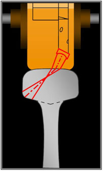
The transducers are housed in fluid-filled wheels mounted in a roller search unit carriage that couple the transducers to the rail (see Figure 1 below). A liquid couplant consisting of a thin film of water mixed with glycol or calcium facilitates the transmission of ultrasonic energy from the transducers into the rail. The transducers are set at different angles to achieve the best inspection coverage possible.
Sperry Rail Services (SRS) Car 965 is equipped with their B-Scan technology and equipment. With this system, there are 2 wheels with twelve transducers per rail — six transducers in each wheel: 2 zero-degree or vertical-looking probes, one forward-looking and one rear-looking transducer nominally aligned at 45 degrees (actually at 37.5 degrees), and six 70-degree probes that divide the rail head into 3 zones – gauge, centre and field – looking forward and reverse. Two additional “side-looking” modified 70-degree probes look at each rail head at a lateral angle for vertical separations for a total of 12 transducers on each rail. This orientation has been optimal for detecting defects transverse to the rail, however it is affected by defect orientation and changes in rail profile and surface anomalies that interfere with the transmission of sound entering the rail.
In addition to the B-Scan system, Car 965 is also equipped with the X-Fire system that incorporates 2 additional transducers per rail that optimize the ultrasonic entry point, angle (17° to the gauge face) and skew to avoid surface anomalies. The system improves the detection of oddly oriented transverse defects and the detection of TDs under shells that the standard angle transducers would normally miss.
