Main-track derailment
Canadian National Railway
Train Q19771-09
Mile 48.41, Skeena Subdivision
Kwinitsa, British Columbia
The Transportation Safety Board of Canada (TSB) investigated this occurrence for the purpose of advancing transportation safety. It is not the function of the Board to assign fault or determine civil or criminal liability. This report is not created for use in the context of legal, disciplinary or other proceedings. See Ownership and use of content. Masculine pronouns and position titles may be used to signify all genders to comply with the Canadian Transportation Accident Investigation and Safety Board Act (S.C. 1989, c. 3).
Summary
On 15 November 2014, at 0607 Pacific Standard Time, Canadian National train Q19771-09, travelling westward at approximately 32 miles per hour, derailed 1 locomotive and 8 intermodal flat cars consisting of 17 platforms at Mile 48.41 of the Skeena Subdivision. No injuries were reported and no dangerous goods were involved.
1.0 Factual information
1.1 The accident
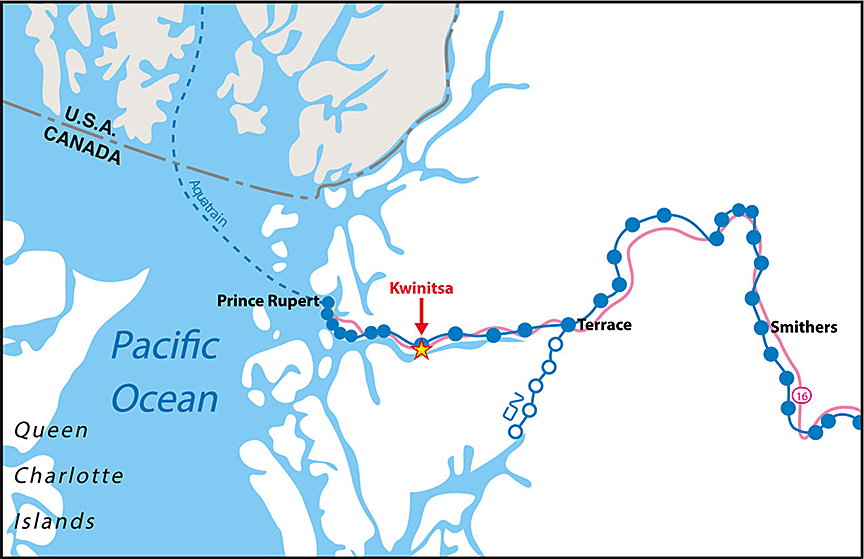
On 15 November 2014, at 0607,Footnote 1 Canadian National (CN) train Q19771-09 (the train) was travelling westward at approximately 32 miles per hour (mph) when it derailed 1 locomotive and 8 intermodal flat cars at Mile 48.41 of the Skeena Subdivision near Kwinitsa, British Columbia (Figure 1). The conventionalFootnote 2 train was composed of 2 locomotives and 153 loaded intermodal flat cars. It was 9382 feet in length and weighed 6760 tons. There were 34 containers onboard the 17 derailed platforms, containing products such as peas and lumber. No dangerous goods were involved.
The train had departed Smithers, British Columbia, at approximately 2350 on 14 November, travelling westward initially on the Bulkley Subdivision. Once the train had fully occupied the main track, Trip OptimizerFootnote 3 (TO) was engaged, taking over operational control of the train. During the train's movement over the Bulkley Subdivision, there were 2 meets: 1 with train Q19851-14 between Fleming and McLeod, and another with train A46051-15 at Andimaul. During these meets, neither train was required to stop.
The train departed Terrace, British Columbia, at 0400 on 15 November, travelling westward on the Skeena Subdivision. On this subdivision, the train passed 3 hot bearing detectors (HBD), which included dragging equipment detectors (DED) and hot wheel detectors (HWD), located at Mile 5.1, Mile 17.0, and Mile 32.2. No exceptions were noted at the 3 detector locations. At approximately 0500, the train entered the siding at Salvus (Mile 36.5) for a meet with opposing train G84651-15 (train 846). The train was stopped for approximately 40 minutes before train 846 arrived. The crew gave train 846 a mandated roll-byFootnote 4 inspection. After the inspection, and upon resumption of westward movement, a wheel slip alarm was noted on the Smart Display Integrated System (SDIS) screen on the lead locomotive. Intermittent wheel slip alarms are not uncommon when locomotives are pulling with high tractive effort, such as when resuming movement after being stopped.
Once the train had fully occupied the main track, TO was re-engaged. The locomotive engineer noted that the train seemed to take slightly longer than expected to accelerate. About 10 miles west of Salvus at Mile 45.9, the train passed over another HBD and received a “no defects” message. About 2.5 miles further west, as the head end proceeded over the west siding switch and associated frogFootnote 5 at Kwinitsa, the crew felt some surging. Shortly thereafter, a train-initiated emergency brake application occurred. After coming to a stop and performing the necessary emergency radio call, the crew inspected the train.
The following was determined:
- The No. 4 axle of the trailing locomotive, CN 5543, was locked (i.e., not rotating) and the trailing locomotive and the first 8 cars had derailed (totalling 17 derailed platforms).
- The R4 wheel of the trailing locomotive had derailed to the gauge side of the south rail.
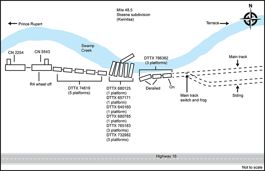
- The first car, DTTX 74619 (5 platforms), had derailed, but remained coupled to the locomotives. The next 6 cars had derailed in an accordion fashion to the north side and into Swamp Creek. The last derailed car, DTTX 786362 (3 platforms), had derailed 2 platforms, but remained upright (Figure 2).
- The north rail was broken mainly in the area where the intermodal cars derailed to the north side into the creek.
- West of the siding switch, the south rail had rolled or was displaced for approximately 300 feet.
Soybean product entered the adjacent waterway (Swamp Creek) from at least 1 of the damaged containers during the derailment. Additional soybean product entered the waterway after the derailment due to the continuous tidal flushing through the damaged containers. Once saturated, the soybeans became neutrally buoyant, which resulted in them flowing along the creek bottom with the changing currents associated with rising and falling tides.
Clean-up and restoration operations commenced on 16 November 2014. During the clean-up operations, efforts were made to remove the soybeans from the containers using vacuum trucks. A total of 2 m3 of soybean product was recovered. Wire fences were installed to reduce the downstream movement of the soybeans. An estimated 220 m³ of soybeans ultimately entered the creek. The soybean product migrated approximately 150 m downstream and 70 m upstream from the derailment location.
The damaged cars were removed from the creek. The recovered product was transported to landfill sites in Terrace and Prince Rupert, British Columbia.
Based on the existing conditions on site, the fish habitat in Swamp Creek, and the likely low risk of the soybean product to aquatic resources, no further efforts were made to remove the soybean product that had spilled within the area covered by high tide. Any further attempts to clean up the soybeans, either through vacuuming or manual cleaning, would have resulted in increased sedimentation without the ability to effectively control it.
Degeneration of the soybean product was determined to be relatively slow during the winter months. The remaining spilled soybean product was expected to start decaying in the spring. The decay process would result in an oxygen demand, potentially changing the pH level in warm standing-water conditions. However, due to the tidal nature and watershed characteristics of this site, it was determined that the decaying soybean product would not have a significant impact on water quality. However, the water quality and the distribution of the spilled soybean product were monitored during summer 2015.
1.2 Recorded information
A review of the locomotive event recorders for the 2 locomotives determined the following:
- The wheel slip alarm had begun when the train started to pull westward after the meet at Salvus.
- The alarm continued intermittently up to the time of the derailment, for approximately 24 minutes and over 11 miles.
- The train-initiated emergency brake application occurred at Mile 48.41, while the train was travelling at 32 mph.
1.3 Wayside detection
CN has a network of over 890 HBDs, spaced approximately 12 to 15 miles apart on mainline track. These detectors are interconnected to a communications network, which allows CN to access the roller bearing and wheel temperature data at a centralized control centre that is staffed on a 24-hour basis by rail traffic controllers (RTCs) and RTC mechanical technicians). All HBDs are integrated with DEDs; more than 600 HWDs are co-located with the HBD/DEDs.
HBD/HWDs measure the amount of heat produced by roller bearings and wheels as they pass over the wayside scanners. They consist of 2 bearing scanners, 2 wheel scanners (at most locations), a DED, and 4 transducers (i.e., advanced transducers and gating transducers). All transducers are bolted to the rail at a specific measurement to detect the wheels of the train. The advanced transducers are used to activate the HBD system on a train's approach. The gating transducers are designed to initiate the sampling rate of the scanners, count axles, and detect train presence.
The scanners analyze 28 heat samples per wheel and bearing to look for abnormal heat readings. If a heat reading exceeds the predetermined heat thresholds, an alarm message will be immediately broadcast to the train over a designated radio channel. The system is designed to give an end-of-train message after the train has fully passed the site and all wheels/bearings have been scanned. The system will broadcast over the designated radio channel whether the train has no defects, or will list a summary of alarms detected on the train. If a hot wheel, hot bearing, or dragging equipment alarm is activated, the RTCs and RTC mechanical technicians at the centralized control centre will also receive a pop-up alarm on their computer screen.
The HBD/HWD system has the capability to calculate train speed, axle spacing, train length, direction, axle counts, and car counts. The system stores the results for all trains for later retrieval. The data can also be viewed on CN's Wayside Information Management system. The system is designed to announce only to trains or equipment containing at least 4 axles, eliminating the announcements for high-rail vehicles passing over the site. All sites can deliver custom radio messages. At the time of the occurrence, the end-of-train radio message did not include “total axles.”
In this occurrence, after departing Terrace, the train travelled over 4 HBD/HWD/DEDs at Mile 5.1, Mile 17, Mile 32.2, and Mile 45.9, which is between the siding at Salvus (Mile 36.2) and the derailment site (Mile 48.5). The recorded temperatures for the damaged wheels on the trailing locomotive were less than 100 °F at the first 3 detector sites. No alarms were produced by any of the detectors.
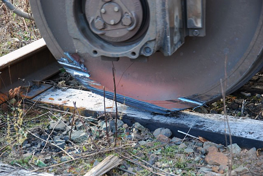
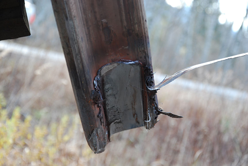
In this occurrence, the locked No. 4 axle on the trailing locomotive prevented the wheels from rotating. These wheels were sliding along the top of the rail head, resulting in wear to the wheel tread and rail burn damage (photo 1 and photo 2). As the wear progressed, the wheel flanges began to extend down below the head of the rail to a point where they made contact with the 2 inner heat-measuring transducers, dislodging them. Although the dislodged transducers remained operable, they could not take readings because they were out of alignment. When the transducers were knocked off the rail entirely, the detector stopped receiving pulses associated with train movement and began to process the end-of-train message. The train received a “No Alarms” message over the designated radio channel. However, only 9 axles (i.e., the 6 axles of the lead locomotive and the first 3 axles of the trailing locomotive) were measured by the bearing and wheel scanners.
Detectors on CN's system are set up to differentiate defects through the use of audible tones communicated over the train standby radio channel. When no defects are noted in the inspection, the automated message is broadcast approximately 30 seconds after the train has passed over the detector. For defects identified during the inspection, an immediate broadcast is made over the train standby channel.
Recorded information for this HBD indicated that the train activated the site at 0602:36. The train was proceeding at about 35 mph (i.e., 51.3 feet per second). At this speed, it would have taken about 3 minutes for the entire train (9382 feet) to clear the HBD location and then another 30 seconds for the system to start broadcasting the inspection results.
With the gating transducers dislodged, the HBD system broadcast the results approximately 30 seconds after the first 9 axles had passed (i.e., about 35 seconds after the site was activated). The crew did not take note of receiving the HBD inspection results earlier than anticipated.
The recorded measurements for the wheels of the locked axle on the trailing locomotive were 554 °F and 545 °F. As CN's warm wheel range was 300 °F to 557 °F, the readings did not reach the hot wheel alarm threshold, and no alarms were indicated by the HBD/HWD/DED site. The warm wheel readings, however, resulted in a pop-up message on the RTC mechanical technician's screen. There was no opportunity for follow-up action by the RTC mechanical technician, because the train derailed shortly after passing over the detectors.
HWDs are not specifically designed to detect heat that is generated by sliding wheels ‑ they are specifically focused, aimed, and calibrated to measure heat that results from friction when brake shoes come into contact with rotating wheels. In addition, hot wheel alarm thresholds were not established to consider the heat generated by sliding wheels.
1.4 Skeena Subdivision
The Skeena Subdivision is a single main track that begins in Terrace, British Columbia (Mile 0.0), and runs west to Prince Rupert, British Columbia (Mile 94.6). Train movements on this subdivision are governed by centralized traffic control (CTC) as authorized by the Canadian Rail Operating Rules (CROR) and supervised by an RTC in Edmonton, Alberta. The maximum track speed for freight trains in the vicinity of the derailment is 40 mph.
The Skeena Subdivision is equipped with 7 HBD/HWD/DED systems, which were located at Mile 5.1, Mile 17.0, Mile 32.2, Mile 45.9, Mile 60.6, Mile 75.2, and Mile 84.0.
In the vicinity of the derailment, the track was 136-pound continuously welded rail manufactured by Sydney Steel Corporation in 1992. The rail was secured to the double-shoulder tie plates with 5 spikes per tie. The ties were 8 feet 6 inches hardwood. The ballast was standard 3½ inch rock.
1.5 Train information
The crew comprised a locomotive engineer and a conductor. Both crew members were qualified for their respective positions, met regulatory rest requirements, and were familiar with operating over the Bulkley and Skeena subdivisions. The conductor was also a qualified locomotive engineer.
1.6 The locomotives
The lead locomotive (CN 2254), which weighed 200 tons, was a 4400 horsepower General Electric ES44DC (Evolution Series - EVO) locomotive, with 6 axles and 6 traction motors. The trailing locomotive (CN 5543), which weighed 184 tons, was a 3800 horsepower EMD SD60 locomotive, with 6 axles and 6 traction motors. Both locomotives were in serviceable condition and were operating as intended.
1.7 Trip Optimizer
Trip Optimizer (TO) is an energy management system installed on the locomotive that helps minimize fuel usage and in-train forces by automatically controlling the throttle and dynamic brake functions. By reducing in-train forces, it can also reduce the likelihood of train separations and damage to customers' goods. The TO system is similar to the cruise control system on a car. At CN, TO was installed on all General Electric ES44DC (EVO) locomotives equipped with SDIS screens, including the lead locomotive in the occurrence train.
According to General Electric's brochure, TO includes the following functions:
- An optimized trip plan is built for each train over a given territory.
- The throttle, dynamic braking (head end), and distributed power (remotely located locomotives) are automatically controlled.
- Horsepower, speed, wheel slip, engine health, rail quality, and wind effect are monitored.
- Closed-loopFootnote 6 auto control of throttle and dynamic brakes with constant operator supervision and return to control at any time is available.
- Auto-independent distributed powerFootnote 7 for train handling of longer trains over difficult terrain is available.
When operating the train manually, the locomotive engineer controls speed and braking using visual feedback from the interface parameters, speed-limit information from the environment, memory retrieval of rules and procedures, and training and experience. Within this closed-loop control strategy, the locomotive engineer can manage the planned speed, the demanded speed, and the actual speed using immediate real-time feedback.
There are 2 tasks for the locomotive engineer in a closed-loop control system:Footnote 8
- Data gathering: Observe and interpret vehicle and system state information through both visual and auditory information channels.
- Control command: Use the perceived data, in conjunction with operating rules and regulations, to make control decisions and physical actions (throttle and brake control).
Either of these tasks can be automated. Automated data gathering involves display automation that facilitates data perception. Automated command control involves supervisory control systems that take over control of some or all of the physical adjustments of the locomotive. Supervisory speed control can vary from basic cruise control to full autopilot, where speed would be programmed as a function of vehicle position.
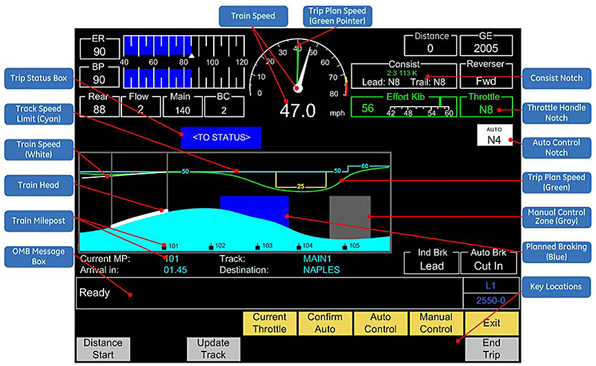
In the case of TO, both data gathering and control command are automated through a full autopilot supervisory control system. The interface between TO and the locomotive engineer is the TO Running Screen on the SDIS (Figure 3).
When pulling away from a stop, such as at the siding at Salvus, the locomotive engineer is in Manual Control until all TO auto control conditions have been met. These conditions include the following:
- A minimum speed is reached.
- The train is operated clear of the station or the siding.
- All active faults or alarmsFootnote 9 (that TO manages) have been cleared.
Once these conditions are met and TO is engaged, the locomotive engineer is no longer manually controlling the speed of the train.
While the train is in auto control, the locomotive engineer is required to monitor TO using the SDIS screen to ensure safe train operation. The locomotive engineer resumes Manual Control if required. The operating requirements in the TO Procedure GuideFootnote 10,Footnote 11 specify (in part) the following:
… compliance with all operating rules and safe train handling procedures remains the responsibility of the LE [locomotive engineer]. Failure to apply proper vigilance and to provide for adequate stopping distances may result in a train movement past a signal. To maintain safe train operation when in Auto DB [dynamic braking] mode, the locomotive engineer must continuously monitor DB effort. Any anomaly detected by the LE which impacts safety shall be a cause for immediate termination of TO.
TO remains engaged until either the train reaches a planned area of Manual Control or an unplanned event occurs. In these situations, the locomotive engineer takes control. For unplanned events (e.g., if TO detects an error where an action is required), audible alarms and SDIS notification result, and an automatic transition to Manual Control without notification occurs.
At the time of the occurrence, TO had been implemented on 318 CN locomotives, less than 25% of CN's fleet. A locomotive engineer would typically operate locomotives with TO about 30% to 50% of the time. Otherwise, the locomotive engineer would be operating non-TO locomotives with full manual control. For trains equipped with TO on the lead locomotive, TO would typically be engaged for approximately 50% to 60% of the trip.
1.8 Implementing new technology
Transport Canada's Safety Management Systems Regulations require railway companies to
- identify safety issues and concerns, including those associated with human factors, third parties, and significant changes to railway operations;
- evaluate and classify risks by means of a risk assessment.
At CN, formal risk assessments were being performed in a systematic and structured manner prior to implementing changes in operations. These assessments evaluated and classified the risks associated with the introduction of new technologies. Training had also been provided to employees who perform these risk assessments.
Risk assessments of new technology, or other factors that may cause significant changes to operations, were an integral part of CN's safety management system.
1.9 Implementation of Trip Optimizer at Canadian National Railway
CN began implementing TO in 2009. On CN's BC North territory, which includes the Bulkley and Skeena Subdivisions, TO was implemented in 2012. Prior to implementation, CN performed a risk assessment that focused on the physical integration of the system with the locomotives. CN also worked jointly with General Electric, the manufacturer and product developer of TO, to develop a training program. The training program and associated procedure guides were updated with each TO system upgrade.
When a qualified locomotive engineer moved into a TO-designated subdivision, the they would receive the updated TO training and the procedure guide. All new locomotive engineers received TO training as part of their locomotive engineer training. The locomotive engineer (and conductor) training for TO consisted of about 4 hours of classroom time, which included a PowerPoint presentation explaining how TO works and its capabilities. Follow-up refresher training for TO was also being conducted, including references to documentation, training at terminals, and ride-alongs with other train crews.
1.10 Research on automation of train operating tasks
A human factors analysis for another in-cab automated system, the European Rail Traffic Management System (ERTMS), determined that automating a significant part of the train driver's task resulted in fewer psychomotor tasks and fewer visual tasks (as information is combined on the in-cab display). Over a typical trip, the train driver could have up to 1000 fewer cognitive tasks to consider. Implementation of this type of system had resulted in a shift from a proactive, anticipatory driving strategy toward a more reactive monitoring strategy. Such a shift was shown to produce low-workload situations that could have the following effects:
- Low workload and monotonous tasks can lead to increases in feelings of sleepiness and tiredness, as this reduces the individual's arousal levels.Footnote 12 In particular, long periods with minimal control inputs can lead to passive fatigue.Footnote 13 If an individual is already fatigued, low workload with minimal inputs could exacerbate the perception of that fatigue.
- Reductions in workload and arousal levels may lead to corresponding reductions in vigilance. Vigilance is associated with states of sufficient alertness to monitor the environment effectively, with a particular emphasis on scanning for potentially dangerous stimuliFootnote 14 A study of the automation effects on locomotive engineers found that vigilance was poorer with high levels of automation and that this effect worsened with time on task.Footnote 15
- Decreased vigilance has been shown to reduce the overall detection rate of critical stimuli over the duration of a task.Footnote 16 The same has been seen for in-car automation technologies such as cruise control. Individuals perform better on secondary tasks with automated primary tasks, but are generally slower in detecting hazards Footnote 17
As a result of this research, the Rail Safety and Standards Board (RSSB) in the United Kingdom advised that with the introduction of new technologies, driver training needed to be updated to reflect changes to non-technical skills. This additional training could include skills such as attention to detail, overall awareness, maintaining concentration, and anticipation of risk.Footnote 18
In addition, the U.S. Department of Transportation compared the different levels of automation relating to train operations (i.e., cruise control to full autopilot).Footnote 19 It was determined that for normal operations, full automation facilitated situational awareness of the overall driving task, as the automation freed up attentional resources to perform secondary tasks and fault monitoring. However, some operators reported that they felt “out of the loop” with the primary task. This highlighted that there could be problems maintaining awareness when there were complex faults on the primary task, especially in the presence of any complacency or fatigue.
1.11 Locomotive alarms
Modern locomotives have computer control systems that monitor many aspects of the locomotive's operation. For example, the electrical and mechanical operations of a locomotive are monitored for faults that affect safe operation. Depending on the type and model of the locomotive and the systems capabilities, each system will display faults in a different way.
When locomotives are connected together through multiple unit (MU) cables, faults identified by 1 locomotive control system are transmitted to the other locomotives. The MU cable provides a 27-pin connection, of which pin 10 is designated for the wheel slip alarm system (Table 1). However, when a fault is transmitted between locomotives, the resulting alarm is not always displayed in the other locomotive(s) in the same way. In addition, not all of the information relating to the fault is necessarily displayed.
The Association of American Railroads (AAR) Manual of Standards and Recommended Practices stipulates that the urgency of rail information conveyed by an alarm shall be indicated by the background colour (that is, alarms with red backgrounds are the most urgent, alarms with yellow backgrounds are less urgent, and alarms with white backgrounds are the least urgent).Footnote 20
In this occurrence, the lead locomotive (2254) was an ES44DC locomotive built in 2006. The trailing locomotive (5543) was an SD60F locomotive built in 1989. Both the ES44DC and the SD60F locomotives have their own warning design approach, including how the WHEEL SLIP indicator is presented in the locomotive. When these 2 types of locomotives are connected, any alarms from the trailing locomotive (SD60F) would be displayed to the train crew in the lead locomotive (ES44DC). For both the ES44DC locomotive and the SD60F locomotive, the WHEEL SLIP indicator is displayed as white with black text.
| SHORT HOOD | LONG HOOD | WIRE | FUNCTION | SCHEMATIC LOCATION |
|---|---|---|---|---|
| 1 | 1 | PRS | POWER REDUCTION SETUP | J1-C7 |
| 2 | 2 | SG | SIGNAL & ALARM BELL | H-C4 |
| 3 | 3 | DV | D THROTTLE | H3-E1 |
| 4 | 4 | N | CONTROL NEGATIVE | U4-B5 |
| 5 | 5 | ES | EM. SANDING | H2-C9 |
| 6 | 6 | GF | GENERATOR FIELD | J1-C9 |
| 7 | 7 | CV | C THROTTLE | H3-E8 |
| 8 | 8 | RE | REVERSE & FORWARD | J-ES |
| 9 | 9 | O | FORWARD & REVERSE | J-D2 |
| 10 | 10 | WS | WHEEL SLIP | H-C1 |
| 11 | 11 | BA | SPARE | N-A5 |
| 12 | 12 | BV | B THROTTLE | H3-E6 |
| 13 | 13 | PC | CONTROL POSITIVE | U2-E9 |
| 14 | 14 | SN | SPARE | N-A3 |
| 15 | 15 | AV | A THROTTLE | H3-E2 |
| 16 | 16 | ER | ENGINE RUN | H3-E9 |
| 17 | 17 | B | DYNAMIC BRAKING SET-UP | J1-C0 |
| 18 | 18 | US | SPARE | N-A4 |
| 19 | 19 | NN | CONTROL NEGATIVE | U4-E7 |
| 20 | 20 | BW | DYNAMIC BRAKE WARNING | H-A7 |
| 21 | 21 | BC | DYNAMIC BRAKE START | J1-C3 |
| 22 | 22 | CC | COMPRESSOR SYNCHRONIZATION | H2-C4 |
| 23 | 23 | SA | SAND | H2-C1 |
| 24 | 24 | BC | BRAKING EXCITATION | J1-C4 |
| 25 | 25 | HL | MU HEADLIGHT | K1-A6 |
| 26 | 26 | SV | SPARE | N-A3 |
| 27 | 27 | RV | SPARE | N-A2 |
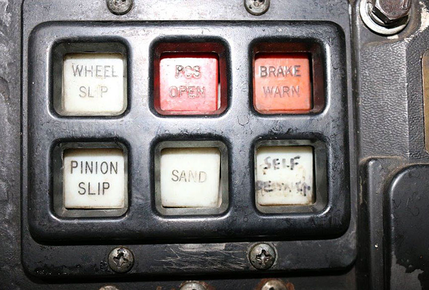
For the SD60F locomotive, its wheels and the relative power being consumed by the traction motors are continuously monitored. If there is an anomaly, a WHEEL SLIP indicator is generated. The WHEEL SLIP indicator is 1 of a group of 6 indicators on an overhead panel above the locomotive engineer position (Photo 3). The indicator is white with black text and is used to alert the crew to 5 possible wheel-related faults and a general Super Series failure.Footnote 21
- Fault 1: Locked powered wheel (locked axle)
This is an abnormal locked wheel fault. It is not a common transitory wheel fault, such as wheel slip and wheel slide. It requires immediate action, as the fault is unlikely to rectify itself. - Fault 2: Slipped pinion
This is an abnormal fault that requires immediate action. - Fault 3: Wheel slip
This is a transitory intermittent fault where the wheel spins. It usually occurs in poor (rail surface) conditions. The indicator informs the operator that the fault is being managed by the wheel slip control system, which may include automatic sanding. This does not require immediate action. - Fault 4: Wheel slide
This is a transitory locked wheel fault where the wheels are skidding. It usually occurs when applying dynamic braking. The indicator informs the operator that the fault is being managed by the wheel slide control system. This does not require immediate action. - Fault 5: Wheel over speed
This is a transitory fault that occurs with excessive speed. The system automatically corrects itself.
Table 2 summarizes how the wheel-related faults are displayed to the train crew and how the train crew should normally respond.
| Description | Presentation | Urgency/Action | |||||
|---|---|---|---|---|---|---|---|
| Fault | State | Condition | Visual | Cadence | Audio | ||
| 1. | Locked powered wheel | Abnormal | Anytime | WHEEL SLIP | Lit continuously while powered | No | Immediate action / stop |
| 2. | Slipped pinion | Abnormal | Anytime | WHEEL SLIP | Lit steadily or flash | No | Immediate action / stop |
| 3. | Wheel slip | Normal wheel slip control | Poor conditions | WHEEL SLIP | Occasional flash | No | No immediate action |
| 4. | Wheel slide | Normal wheel slide control | With dynamic brake | WHEEL SLIP | Intermittent flashing | No | No immediate action |
| 5. | Wheel over speed | Over speed | Excessive speed | WHEEL SLIP | Flash on and off | No | System automatically corrects itself |
| 6. | Super Series failure | Super Series failure | Poor conditions / 1.5 mph+ | WHEEL SLIP | Occasional, irregular flashing | No | Report Continue |
All of the different wheel-related faults are presented on the same white WHEEL SLIP indicator. These faults did not have an associated audible alarm. Train crews would typically distinguish between the type of fault in the following ways:
- Text
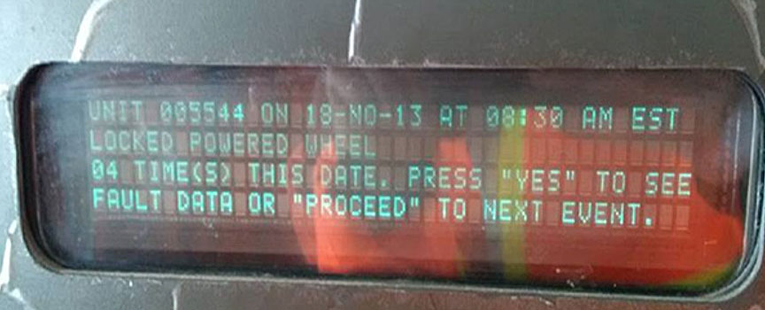
Urgent faults that required immediate action (faults 1 and 2) were accompanied by a computerized descriptive text. This text was presented on a panel behind the locomotive engineer. In the case of a locked powered wheel (locked axle), a text message indicating LOCKED POWERED WHEEL was presented on the human-machine interface display panel (Photo 4). - Context
Faults can vary according to context (e.g., poor environmental conditions [fault 3] versus dynamic braking [fault 4] versus excessive speed [fault 5]). - Cadence
Each fault had its own cadence on the visual display on the overhead panel. The different patterns included the following: lit continuously while powered; lit steadily or flash; occasional flash; intermittent flashing; flash on and off; and occasional and irregular flashing.
The ES44DC locomotive also monitors its wheels and the relative speed at which they are turning. In comparison with the display panel in an SD60F locomotive, if a wheel-related anomaly occurred on the ES44DC locomotive, 1 of the following indicators was displayed on the flat-screen SDIS:Footnote 22
- LOCK AXL
If a locked powered wheel (locked axle) occurred, a LOCK AXL indicator was generated. This indicator was yellow with black text and situated on the centre-left of the alarm block of the SDIS. It was accompanied by an audible alarm. - PINION SLIP
If a Slipped Pinion occurred, a PINION SLIP indicator was generated. This indicator was red with white text and situated on the centre-right of the alarm block of the SDIS. It was accompanied by an audible alarm. - WHEEL SLIP
If a Wheel Slip, Wheel Slide, or Wheel Over-Speed occurred, a WHEEL SLIP indicator was generated. This indicator was white with black text and situated on the far left of the alarm block of the SDIS. It was not accompanied by an alarm.
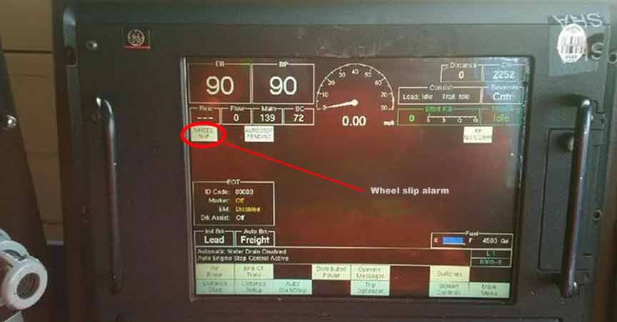
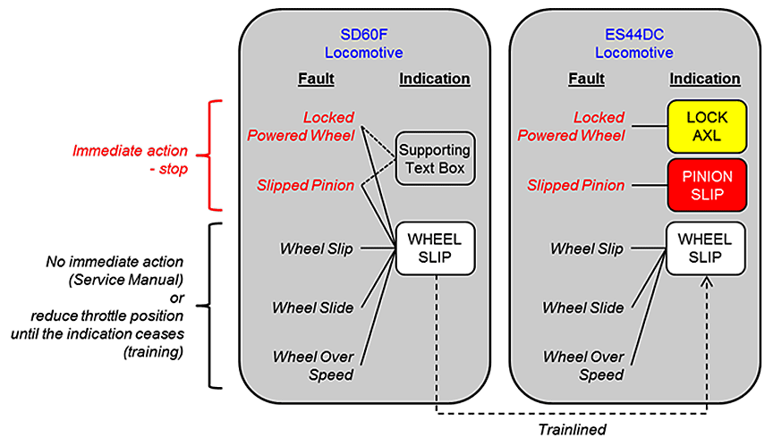
If an SD60F locomotive was trainlinedFootnote 23 with an ES44DC locomotive, as was the case in this occurrence, wheel-related faults from either locomotive were presented on the SDIS screen of the lead ES44DC locomotive (Photo 5):
- If the fault was related to a wheel set on the ES44DC locomotive, the possible indicators were a yellow LOCK AXL text message, a red PINION SLIP text message, or a white WHEEL SLIP text message.
- If the fault (regardless of type) was related to a wheel set on the SD60F locomotive, only the white WHEEL SLIP text message was displayed, as all wheel-related faults for the SD60F locomotive were trainlined using this indicator (Figure 4).
1.12 Locomotive engineer training relating to wheel slip
CN's locomotive engineer training courseFootnote 24 covered the different faults and presentations of the WHEEL SLIP indicator for various locomotives, including the SD60F and the ES44DC. The training relating to these 2 locomotives indicated that a locked powered wheel or slipped pinion fault requires an immediate stop and inspection. However, the training did not specifically reference the situation when an SD60F locomotive is trainlined with an ES44DC locomotive. In addition, there was no specific training or guidance on distinguishing non-urgent and urgent faults on the white WHEEL SLIP indicator of the ES44DC SDIS screen.
The section on wheel slip in CN's Locomotive Engineer Operating Manual states the following:
The wheel slip light will illuminate in the lead locomotive when any wheel in the consist is slipping. Automatic sanding will occur to correct many wheel slips. Use trainline sanding only when lead truck sanding proves inadequate.
Manual Wheel Slip Correction Procedure: If the wheel slip detection system does not correct the wheel slip, perform the following procedure:
- Reduce throttle position until wheel slip indication ceases.
- Apply sand, if possible.
- Do not increase throttle until wheel slip stops.
If a wheel slip light remains illuminated or flashing during locomotive operation, it may indicate a locked or sliding wheel. Stop the locomotive immediately and perform a roll-by inspection to ensure all wheels are rotating freely.
Slipped Pinion: An intermittent wheel slip light, slipped pinion warning, or brake warning will indicate a possible slipped pinion condition. The load meter will also fluctuate. On newer high HP locomotives, the alarm bell will sound. Cut out affected traction motor and ensure wheels turn freely.Footnote 25
1.13 Line of sight assessment toward the rear of the train
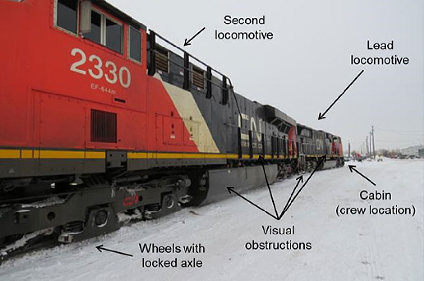
Before the derailment, the wheels on the No. 4 axle of the trailing locomotive had been sliding along the top of the rail from 0543 to 0607—about 24 minutes. This wheel slide would have produced sparks and smoke for some of the time between the departure from the siding at Salvus to the derailment location. These external visual cues, if observed, would have indicated a problem and the need for an immediate stop to inspect the train. However, the crew members were not aware of the sparks and smoke.
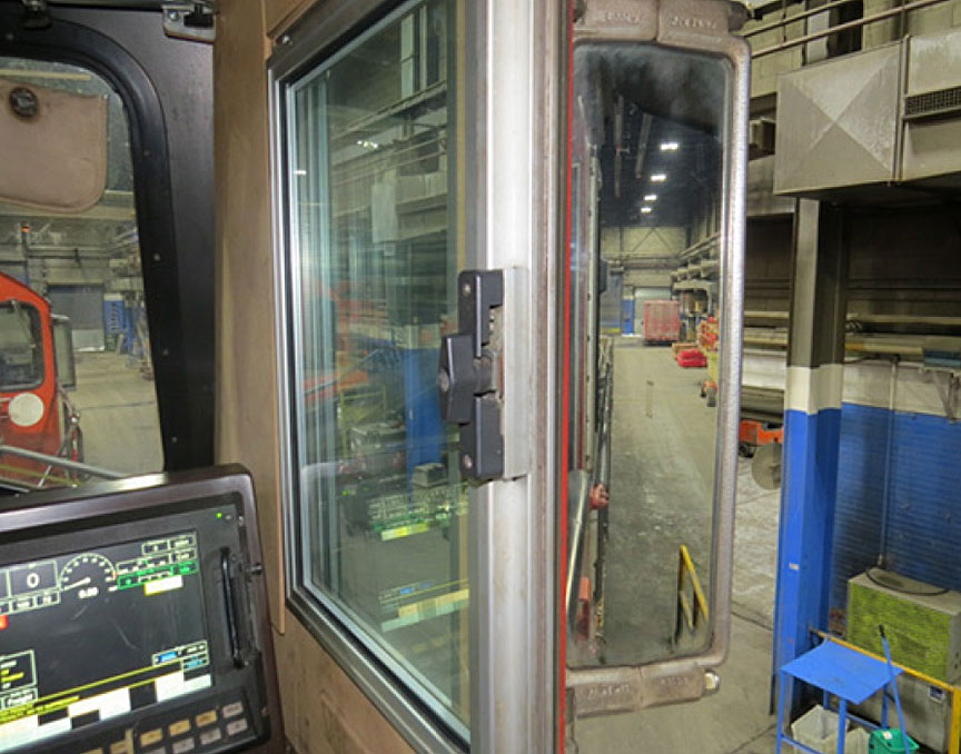
During this time, the skies were clear, but dark. There was a rear-view mirror on each side of the locomotive cab positioned such that the crew members could view toward the rear of the train without turning away from the forward-facing position (Photo 6). There was also a rear window on each side of the locomotive cab. By turning around, the train crew could use these rear windows to view the train behind them. However, the train crew's view toward the rear of the train may have been obstructed by the following:
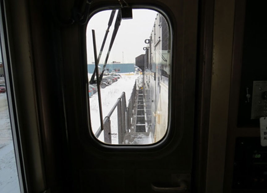
- On the right side (locomotive engineer's view), there was a raised walkway leading from the cab to the rear of the locomotive (Photo 7).
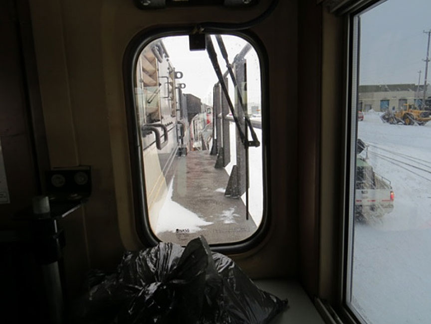
- On the left side (conductor's view), there was a raised platform extending from the engine compartment (Photo 8).
These physical features extended along each side of the locomotive, obstructing the view of the wheels on the second locomotive. As the lead locomotive and the second locomotive were situated back to back (Photo 9), the locomotive engineer's rear view was affected by the right-side obstructions of the lead locomotive and the left-side obstructions of the second locomotive. Similarly, the conductor's rear view was affected by the left-side obstructions of the lead locomotive and the right-side obstructions of the second locomotive.
There are a number of curves on the Skeena Subdivision between the siding at Salvus and the derailment site. Had the crew been looking back while travelling through a curve, a clearer view of the sparks and smoke from the locked axle may have been visible.
1.14 Fatigue and performance for train crews
Fatigue is intrinsically linked to sleep. Disruptions to sleep or sleeping patterns in personnel occupying safety critical positions can result in performance decrements that increase the risk of incidents and accidents. Disruptions include acute sleep disruptions, chronic sleep disruptions, continuous wakefulness, circadian rhythm disruptions, sleep disorders, or other medical and psychological conditions, illnesses, or drugs that affect sleep or sleepiness.
For train crews, fatigue has been shown to slow reaction time, cause late braking and poor conformance to train driving requirements,Footnote 26 increase risk taking, and reduce ability to solve complex problems.Footnote 27 Fatigue can also affect attention, attentiveness, and general cognitive functioning.
Humans have a number of daily (circadian) biological rhythms that influence the body's internal and external functions. Research suggest that hundredsFootnote 28 of these types of rhythms exist, such as body temperature, heart rate, subjective fatigue, attention, drowsiness, peak expiratory flow, and grip strength. There are also circadian rhythms for performance and cognitive functioning.Footnote 29
Performance and cognitive functioning are generally worst during the period when circadian rhythms dictate sleep. For train crews, performance and cognitive functioning are generally worst during the period when circadian rhythms dictate sleep. Performance on specific measurements such as reaction time,Footnote 30 arithmetic and signal detection,Footnote 31 and reaction to train safety alarm alertsFootnote 32 have all been demonstrated to be worst during the night.
Many circadian rhythms are interdependent and synchronized to each other, as well as being synchronized to time of day. Researchers have also found that circadian rhythms can become desynchronized when there are changes in sleep–wake patterns. Desynchronization occurs because each biological rhythm adapts to a new sleep–wake pattern at a different rate. For those who work night shifts on a continuous basis, their circadian patterns will change and adapt over time. However, for those who work night shifts on an occasional basis, their circadian patterns will not adapt to working at night.
Researchers have determined that adjustment of the human circadian system resulting from changes to the sleep–wake pattern occurs at a rate of 1 to 1.5 hours per day. Therefore, adjusting from being awake during the day to being awake at night (i.e., a 12-hour difference) would normally take between 12 and 18 days for a complete adjustment to allow for optimum performance to return. Operating only a few night shifts, especially sporadically, will not result in optimum circadian adjustment, and performance will continue to be affected by circadian lows. In addition, the degree to which performance is affected may be impacted by other fatigue risk factors, such as chronic fatigue.
Even if circadian rhythms are not desynchronized, there are 2 periods of maximum drowsiness in every 24-hour period. Although these times can vary from person to person, the principal drowsiness period for diurnal workers generally occurs between 0300 and 0500. A second drowsiness period occurs between 1500 and 1700. During these periods of drowsiness, physiological systems are at their lowest level. Irrespective of motivation and circumstances, a person can have a difficult time remaining alert during periods of maximum drowsiness.
Desynchronization can cause fatigue, daytime sleepiness, psychomotor impairment, impaired performance, insomnia, other sleep disturbances, reduced cognitive skills, and muscle fatigue. Symptoms of desynchronization can also result in a further reduction in sleep time and quality. Employees working on shifts with variable start and finish times will constantly be susceptible to the development of desynchronization, regardless of the length of time they have worked variable shifts. Variable sleep times can also be difficult to manage when living with families who have daytime commitments or when anticipating an event such as a work call. Fatigue is known to increase as start-time variability increases.
Less-than-adequate adjustment periods and complex schedules that reduce the predictability of work and social responsibilities increase the risk of fatigue. Mitigations, such as fatigue awareness training, use of caffeine, and strategic napping can be used to reduce the likelihood and impact of performance decrements.
1.15 Variability in crew start time
CN's freight trains, similar to those of other Canadian railways, operate on an unscheduled basis;Footnote 33 consequently, crews are called for trips as required. Trips are assigned to crew members from subdivision pools or lists based on a first-in, first-out system. When crew members finish a trip, their names are placed back into the pool list for reassignment to their next trip.
As trains are not scheduled, crew start times must be estimated using train lineups (i.e., a list of anticipated trains that will be operated). This information will provide an approximation of the arrival time of anticipated trains at their home terminal and their away-from-home terminal.
However, train arrival times can change dramatically depending upon factors such as slow orders on the route, mechanical problems with the train, and planned or unplanned track work. Also, other crew members ahead on the list can become unavailable on short notice. These factors lead to unpredictability of the call times for train crews.
1.16 Work–rest history of train crew
In this occurrence, the locomotive engineer and the conductor started their night shift at 2330. At about 0543, the train departed the siding at Salvus, at which point the locked axle condition initiated. This hazardous condition continued until the derailment at 0607.
Both crew members had worked within the limits prescribed by the Work/Rest Rules for Railway Operating Employees. However, the locomotive engineer and the conductor had each been working a sporadic shift schedule with start-time variabilities before the occurrence. Start-time variability made it difficult to obtain an adequate amount of good-quality sleep, as the available sleep periods occurred across varying circadian rhythm highs and lows. Start-time variability can affect circadian rhythms, which in turn can cause fatigue. The locomotive engineer had not received any fatigue management training.
The work–rest history of the locomotive engineer was as follows:
- In the 6 weeks preceding the occurrence, the locomotive engineer had a steady pattern of day and night shifts from 1700 to 0200–0300 and 0700 to 1300, followed by 24 or 48 hours of rest. This created regular sleep disruptions of 1 night sleeping followed by 1 night working.
- On the day of the occurrence, the locomotive engineer had slept and prepared to work for an early evening shift, but the shift did not start until 2330, at which time he had been awake for several hours. As the shift started late, it would also finish late, which meant that the locomotive engineer was still working at 0500 to 0600, a known circadian low point and a period during which he anticipated he would be sleeping. In the previous 6 weeks, he had worked until this time of the morning only once.
The work–rest history of the conductor was as follows:
- The conductor had worked for 2 weeks in October, taken vacation for 2 weeks, and then returned to work for 2 weeks before the day of the occurrence.
- In the previous 2 weeks, the conductor had a mix of day and night shifts, resulting in sleep opportunities starting at 1200, 1200, 0200, 2000, 0400, 0300, 1300, 1300, and, on the day of the occurrence, 0700.
- On the previous day, the conductor had the opportunity to sleep at night, but in the 4 days previous to that, was either starting or finishing his shift between the hours of 0000 and 0600.
- On the day of the occurrence, the conductor had slept and prepared to work for a late-afternoon shift. However, the shift did not start until 2330, by which time he had been awake for several hours. The conductor was still working at 0500 to 0600, a known circadian low point and a period during which he anticipated he would be sleeping. On the day of the occurrence, the conductor worked through the entire period of 0000 to 0600, something he had not done in the previous 6 weeks.
- Although the crew had opportunities for quality sleep, they also had to contend with the effects of variable shift start times and circadian disruptions.
1.17 Laboratory examination of traction motor (LP244/2014)
The traction motor that was connected to the locked (i.e., not rotating) No. 4 wheel set on locomotive CN 5543 was sent to the TSB Laboratory for detailed examination. The following was determined:
- The traction motor had been rebuilt on 08 September 2012 by Electro Motor Services. At the time of the rebuild, the pinion end bearing fit measured on the traction motor shaft was 0.0007 inch below the minimum limit specified for an EMD ARS model traction motor.
- When a traction motor shaft is undersized, the decreased interference between the shaft and the inner ring can make the traction motor assembly more susceptible to slip.
- The amount of interference between the armature shaft and the pinion end bearing inner ring was sufficient to allow the traction motor assembly to operate normally for some time after the rebuild.
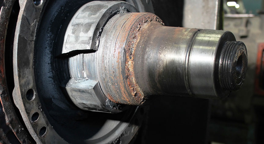
- At some point before the occurrence, operating conditionsFootnote 34 had likely changed, such that the friction provided by the interference fit was insufficient to prevent the shaft from slipping relative to the bearing (Photo 10).
- Once the shaft had started to slip inside the inner ring, friction forces caused extensive wear and heat generation at the fit surfaces. This resulted in overheating of the inner ring to the point where its metallurgical properties changed.
- The train pulled into the siding at Salvus and stopped just before the occurrence. The failure sequence had likely begun by that time, so that the shaft and inner ring were very hot. When the train came to a rest, the shaft stopped rotating in the inner ring. The overheated shaft and pinion end bearing subsequently cooled down and seized together.
- When the train started to move out of the siding, the resulting force was insufficient to overcome the seized shaft and bearing, causing the locked wheel set to be dragged by the train and eventually leading to the derailment.
1.18 Examination of the locomotive alarm system (LP246/2014)
An examination of the locomotive alarm system for the trainlined locomotives determined that
- the wheel slip warning and indication system on the second locomotive (CN 5543) operated as designed;
- the locomotive event recorder of CN 5543 recorded the wheel slip events experienced by the second locomotive;
- the locomotive event recorder of the lead locomotive (CN 2254) recorded the trainlined wheel slip events of the second locomotive;
- the wheel slip warning and indication system of the lead locomotive operated as designed.
2.0 Analysis
Track structure conditions did not play a role in this occurrence. The analysis will focus on the pinion bearing failure and wheel slip alarms of the locomotives, crew scheduling and fatigue, automation of operator functions, and wayside inspection systems.
2.1 The accident
The derailment occurred when the sliding No. 4 wheel set on the trailing locomotive encountered the west siding switch at Kwinitsa. The train had travelled approximately 11 miles with the No. 4 axle locked and the wheels sliding along the rail. The wheels of the No. 4 axle had deformed to the point that the tread on both wheels had worn approximately 4 inches deep, developing flanges on both sides of the rail. The deformed south side wheel (R4) made contact with the frog, causing the wheel to climb and derail to the inside of the rail as the wheel set departed the frog. The lateral stress exerted by the derailed wheel overcame the lateral holding capacity of the track structure, causing the rail to roll, leading to the derailment of the following 8 intermodal cars.
When the train was stopped in the siding at Salvus, the overheating shaft and pinion end bearing on the traction motor assembly of the No. 4 axle cooled down and seized together. The shaft and pinion end bearing had been overheating due to slippage inside the inner ring, which resulted in friction forces, extensive wear, and heat generation at the fit surface. The interference fit between the pinion end bearing inner ring and the traction motor shaft was 0.0007 inch below the minimum limit specified for an EMD ARS model traction motor. The decreased interference between the shaft and inner ring made the assembly more susceptible to slip. In this situation, the amount of interference between the shaft and inner ring was initially sufficient to allow the assembly to operate normally for some time before the slippage started.
Upon departure from the siding at Salvus, the wheel slip alarm had activated and was being displayed on the Smart Display Integrated System (SDIS) screen in the lead locomotive. As intermittent wheel slip alarms are not uncommon when locomotives are pulling with high tractive effort, such as when resuming movement after being stopped, the train crew was not concerned with the activation of this alarm.
From the SDIS screen, the locomotive engineer had no definitive means to determine whether the white wheel slip indicator represented a non-urgent ES44DC fault, a non-urgent SD60F fault, or an urgent SD60F fault. With the SD60F locomotive trainlined to the ES44EC locomotive, the alarm displayed did not provide sufficient information to the train crew to indicate that an urgent fault condition existed.
When the crew resumed westward movement after their meet at Salvus, the locomotive engineer was in manual control until all Trip Optimizer (TO) auto control conditions were met: minimum speed was reached, the train was operated clear of the siding, and all active faults or alarms (that TO manages) were cleared. The TO auto control conditions were met for the lead locomotive, and TO was activated while the trailing locomotive was experiencing an urgent fault (a seized/locked axle). It is likely that the successful re-engagement of TO upon departing the siding indicated to the locomotive engineer that the locomotives were operating without active faults.
About 9 miles after departing Salvus, the train was operating over a hot bearing detector / hot wheel detector / dragging equipment detector (HBD/HWD/DED) site. The HBD/HWD/DED inspection results were announced shortly after the first 9 axles passed by the scanner. The train crew did not notice that this post-inspection announcement was being transmitted much earlier—3 minutes earlier—than normally expected.
2.1.1 Fatigue
The crew members were fatigued at the time of the occurrence. In the previous days, both crew members had had erratic sleep availability periods due to work shifts with variable start and end times. This sleep variability had resulted in circadian rhythm disruptions without sufficient opportunities for adjustment. Other fatigue-causing conditions were noted, including the following:
- The crew's pre-shift rest was mistimed due to their shift start moving to a later start time than expected. The crew started their shift several hours after their last sleep period.
- The crew worked through the night (0000–0600), a general period of circadian low.
- Toward the end of the shift (around 0500), the crew would have experienced a physiological low.
This state of fatigue likely affected the locomotive engineer's ability to recognize the significance of the wheel slip alarm and the slower-than-expected acceleration. Neither crew member recognized the earlier-than-expected HBD/HWD/DED announcement.
2.2 Locomotive alarm information when locomotives are trainlined
A good alarm warning system will help ensure the timely and effective management of relevant faults. The warning system should facilitate 3 levels of operator situation awareness: the perception of elements in the environment, the comprehension of their meaning, and the projection of their status. To achieve this, the warning system must also be compatible with the operator's mental model(s) of the task and situation, and any key elements of information need to be prominently displayed on system screens by means of colour, size, and contrast.Footnote 35
In this occurrence, both locomotives had a separate and distinct approach to locomotive alarm design. The SD60F locomotive had a WHEEL SLIP indicator that was used for 6 different faults, some of which are common and/or transitory faults. Increased use of a fault indicator for non-urgent conditions increases the probability of the fault indicator being overlooked for urgent conditions.
In comparison, the ES44DC locomotive had colour-coded indicators with audible alarms for the LOCK AXL and PINION SLIP alarms (i.e., the 2 urgent faults). The white WHEEL SLIP indicator was used to warn of non-urgent faults (i.e., wheel slip, wheel slide, and wheel over speed).
However, in this accident, the SD60F locomotive was trainlined to the ES44DC locomotive, with the ES44DC in the lead. The wheel-related faults from either locomotive were presented on the SDIS screen of the lead locomotive as follows:
- For faults related to a wheel set on the ES44DC locomotive, the possible indicators were a yellow LOCK AXL text message, a red PINION SLIP text message, or a white WHEEL SLIP text message. Note: both urgent alarms (LOCK AXL and PINION SLIP) are accompanied by audible alarms.
- For faults related to a wheel set on the SD60F locomotive (regardless of type), only the white WHEEL SLIP text message was displayed. None of the alarms are accompanied by an audible alarm.
This means that the white WHEEL SLIP indicator on the SDIS is used for the non-urgent faults of the ES44DC and both the non-urgent and urgent faults of the SD60F. In addition, the trainlined faults from the SD60F locomotive were not accompanied by the supporting text (e.g., LOCKED POWERED WHEEL or PINION SLIP) that would be displayed in the cab of the SD60F locomotive. When different locomotive types are trainlined, if the available locomotive alarm information is not transmitted to the lead locomotive, the train crew may not have sufficient information to respond appropriately to a locomotive alarm, increasing the risk of equipment failure leading to a derailment.
According to the AAR Manual of Standards and Recommended Practices (the Manual), an indicator reflecting a wheel slip condition should be white and of a steady state with no audible alarm, reflecting a least urgent fault. The Manual also indicates that abnormal urgent states, such as the locked axle, should be either red (most urgent) or yellow (urgent) and accompanied by an audible alarm. With a seized pinion (locked powered wheel) on the SD60F trainlined to the ES44EC, the alarm displayed was not consistent with the Manual and was not sufficiently compelling for the locomotive engineer to conclude that an urgent fault was under way.
2.3 Wayside inspection systems
Canadian National Railway's (CN) hot wheel detectors (HWD) are specifically focused, aimed, and calibrated to identify warm and hot wheels resulting from sticking brakes. The measured heat for a wheel would be due to brake shoe friction as the wheel turns. In this occurrence, the heat that developed from the friction of the locomotive wheel sliding on the rail was also measured by the HWD.
The pinion bearing of the No. 4 wheel set traction motor had been in the early stages of failure sometime before the train stopped in the siding at Salvus. The pinion bearing then cooled and seized when the train was stopped in the siding. Upon resumption of the westward movement, the wheels of the No. 4 locked axle were sliding for almost 10 miles, deforming the wheel tread and generating heat readings of up to 554 °F. However, as the hot wheel alarm threshold for CN's HWDs was set at 558 °F, a hot wheel alarm was not activated. Hot wheel alarms thresholds were not established to consider the heat generated by sliding wheels. Nevertheless, the overheating sliding wheel set was in the warm wheel threshold range just before the derailment.
At the time of the occurrence, CN's hot bearing detectors/hot wheel detectors/dragging equipment detectors (HBD/HWD/DED) did not include axle count as a part of the radio announcement provided to the train crew following the inspection. The occurrence train had 424 axles. However, only 9 axles were inspected at the HBD/HWD/DED (Mile 45.8) before the damaged wheel set dislodged the heat sensors. The HBD/HWD/DED inspection results were then announced about 30 seconds later, which was much sooner than should have been expected. The train crew did not notice that the train (over 9000 feet in length) was still passing the inspection location when the HBD/HWD/DED inspection results were being transmitted. If all relevant information (including axle count) is not announced following an HBD/HWD/DED inspection, the train crew may not become aware of an impending equipment problem, increasing the risk of equipment failure leading to a derailment.
2.4 Implementing new technology affecting how trains are operated
Trip Optimizer (TO) has changed the role of the locomotive engineer. While in auto control, TO manages the speed and driving-related tasks that the locomotive engineer would otherwise perform. In this situation, the role of the locomotive engineer becomes a visual monitoring role. This may have had the following effects:
- Increased automation reduces the physical driving component of the locomotive engineer role while increasing the visual monitoring component, especially during the initial engagement.
- While the TO was in auto control, the locomotive engineer would have a low workload role.
- When auto control is active, the locomotive engineer may not be fully aware of what the system is doing (i.e., reduced situational awareness). For example, the displayed speed does not necessarily represent what the locomotive engineer would expect if he were manually controlling the train.
In this occurrence, the locked axle condition produced some drag on the train and affected its acceleration departing Salvus, after TO was activated. The slower-than-expected acceleration was noticed, but was not considered to be unusual feedback while TO is activated, given that TO is a fuel-saving device. In the absence of any real-time feedback, such as that experienced while in manual control, the slower-than-expected acceleration was not considered out of the ordinary and did not prompt a search for a defective condition.
When introducing new technology, it is important to assess the inherent risks and the risks associated with integrating it with existing operations. Assessing such risks enables an organization to manage any operational safety implications by implementing mitigations accordingly. These may include changes to the design or updates to the training, procedures, tasks, and supervision.
Although CN performed a risk assessment on the technical integration of TO, the risk assessment did not specifically include an assessment of
- potential human-factors implications of TO, including those that may have affected fatigue;
- the risks associated with the interoperability of the different technologies used concurrently, e.g., TO and trainlined locomotives with different warning systems.
When implementing new technology affecting how trains are operated, if a comprehensive review of technical and human factors–related consequences is not conducted, the associated risks may not be fully identified and mitigated.
2.5 Crew start times variability
Variable start times for a train crew member can make it difficult to plan for and complete good-quality sleep, especially if the crew member is anticipating a work call. In an attempt to improve predictability of shift start times, railways have implemented improvements to train line-ups, including access to train line-up information.
However, it is likely that shift start variability continues to make it difficult for some train crews in pool service to obtain an adequate amount of good-quality sleep. When shift start time is highly variable, the available sleep periods for crew members tend to occur across varying circadian rhythm highs and lows.
In this occurrence, the crew members were subject to start-time variability in the weeks leading up to the occurrence that left them fatigued. If shift start times are highly variable, train crew members may not be able to obtain good-quality sleep on a regular basis, resulting in fatigue during duty shifts and increasing the risk of accidents.
2.6 Line of sight assessment toward the rear of the train
External visual cues to the rear of the locomotive could be acquired by scanning either the rear-view mirrors or the rear windows. However, viewing the external cues using the mirrors depended on their positioning in relation to the crew members' position. If the mirrors were not set correctly, a representative view would not have been possible without the operator also having to move their body. Further, due to the absence of other visual cues at night, incorrect positioning may not have been noticed.
Even if flames, sparks, and smoke were emitted from the locked axle and sliding wheel set on the trailing locomotive, there were multiple obstructions toward the rear from the crew members' in-cab position. With multiple physical obstructions affecting the view toward the rear of the train, the train crew at times may not have had a clear view of the external cues (e.g., sparks, smoke) originating from the failed No. 4 axle on the trailing locomotive.
3.0 Findings
3.1 Findings as to causes and contributing factors
- The derailment occurred when the sliding No. 4 wheel set on the trailing locomotive encountered the west siding switch at Kwinitsa.
- The deformed south side wheel (R4) made contact with the frog, causing the wheel to climb and derail to the inside of the rail as the wheel set departed the frog.
- The lateral stress exerted by the derailed wheel overcame the lateral holding capacity of the track structure, causing the rail to roll, leading to the derailment of the following 8 intermodal cars.
- When the train was stopped in the siding at Salvus, the overheating shaft and pinion end bearing on the traction motor assembly of the No. 4 axle cooled down and seized together.
- The shaft and pinion end bearing had been overheating due to slippage inside the inner ring, which resulted in friction forces, extensive wear, and heat generation at the fit surface.
- Upon departure from the siding at Salvus, the wheel slip alarm had activated and was being displayed on the Smart Display Integrated System (SDIS) screen in the lead locomotive. As intermittent wheel slip alarms are not uncommon when locomotives are pulling with high tractive effort, such as when resuming movement after being stopped, the train crew was not concerned with the activation of this alarm.
- From the Smart Display Integrated System (SDIS) screen, the locomotive engineer had no definitive means to determine whether the white wheel slip indicator represented a non-urgent ES44DC fault, a non-urgent SD60F fault, or an urgent SD60F fault.
- With the SD60F locomotive trainlined to the ES44DC locomotive, the alarm displayed did not provide sufficient information to the train crew to indicate that an urgent fault condition was under way.
- It is likely that the successful re-engagement of Trip Optimizer served as an indicator to the locomotive engineer that the locomotives were operating without active faults.
- The hot bearing detector / hot wheel detector / dragging equipment detector (HBD/HWD/DED) inspection results were announced shortly after the first 9 axles passed by the scanner. The train crew did not notice that this post-inspection announcement was being transmitted much earlier than normally expected.
- The crew members were fatigued at the time of the occurrence, as they had been experiencing circadian rhythm disruptions in the previous days. This state of fatigue probably affected their ability to recognize the significance of the wheel slip alarm and the earlier-than-expected hot bearing detector / hot wheel detector / dragging equipment detector (HBD/HWD/DED) announcement.
3.2 Findings as to risk
- When different locomotive types are trainlined, if the available locomotive alarm information is not transmitted to the lead locomotive, the train crew may not have sufficient information to respond appropriately to a locomotive alarm, increasing the risk of equipment failure leading to a derailment.
- If all relevant information (including axle count) is not announced following an hot bearing detector / hot wheel detector / dragging equipment detector (HBD/HWD/DED) inspection, the train crew may not become aware of an impending equipment problem, increasing the risk of equipment failure leading to a derailment.
- When implementing new technology affecting how trains are operated, if a comprehensive review of technical and human factors–related consequences is not conducted, the associated risks may not be fully identified and mitigated.
- If shift start times are highly variable, train crew members may not be able to obtain good-quality sleep on a regular basis, resulting in fatigue during duty shifts, and increasing the risk of accidents.
3.3 Other findings
- With multiple physical obstructions affecting the view toward the rear of the train, the train crew at times may not have had a clear view of the external cues (e.g., sparks, smoke) originating from the failed No. 4 axle on the trailing locomotive.
- The overheating sliding wheel set was in the warm wheel threshold range just before the derailment.
4.0 Safety action
4.1 Safety action taken
4.1.1 Canadian National Railway
Following the occurrence, Canadian National Railway reformatted the hot bearing detector / hot wheel detector / dragging equipment detector (HBD/HWD/DED) sites to include axle counts as a part of the post-scan announcement.
This report concludes the Transportation Safety Board's investigation into this occurrence. the Board authorized the release of this report on . It was officially released on 19 July 2016.
