Main-track train derailment
Canadian Pacific Railway
Freight train 205-25
Mile 82.1, Laggan Subdivision
Banff, Alberta
The Transportation Safety Board of Canada (TSB) investigated this occurrence for the purpose of advancing transportation safety. It is not the function of the Board to assign fault or determine civil or criminal liability. This report is not created for use in the context of legal, disciplinary or other proceedings. See Ownership and use of content. Masculine pronouns and position titles may be used to signify all genders to comply with the Canadian Transportation Accident Investigation and Safety Board Act (S.C. 1989, c. 3).
Summary
On 26 December 2014, at 0052 Mountain Standard Time, westbound Canadian Pacific train 205-25 derailed 15 cars at Mile 82.1 on the Laggan Subdivision, near Banff, Alberta. The derailment destroyed the bridge over Forty Mile Creek and cars loaded with fly ash, soybeans and lentils were breached, spilling product into the waterway. No injuries were reported. However, a crew member sought medical attention for fly ash inhalation.
Factual information
The accident
On 26 December 2014, Canadian Pacific Railway (CP) freight train 205-25 (the train) departed Calgary, Alberta, destined for Vancouver, British Columbia. After setting off 10 cars at Gap, the train consisted of 2 locomotives and 77 cars (69 loaded cars and 8 empty cars). The train weighed about 9471 tons and was 4608 feet in length. The crew was made up of a locomotive engineer and a conductor. The crew members were familiar with the territory, met fitness and rest standards, and were qualified for their respective positions.
At 0052,Footnote 1 while passing through the town of Banff (Figure 1), an undesired emergency brake application (UDE) occurred when the train was travelling at 26 mph with the throttle in position 8. When the train came to a stop, the conductor inspected the train and determined that a number of cars had derailed. Before the conductor left the locomotive to perform the inspection, there was no discussion between the two crew members concerning the potential hazards that might be encountered, including the special dangerous commoditiesFootnote 2 near the end of the train. The bridge at Mile 82.3 was destroyed, and some of the derailed cars were on top of the bridge and in the waterway (Forty Mile Creek). At the time of the occurrence, the sky was overcast and the temperature was −20 °C.

Site examination
The derailment occurred in Banff National Park.
The derailment area covered a distance of approximately 2500 feet, from the turnout at Mile 82.0 at the west switch of Banff siding, up to about Mile 82.6. This section of track included a
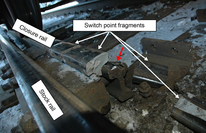
65-foot through-plate girder ballast deck bridge. The switch points and the switch heater at the west switch of Banff siding were destroyed.Footnote 3 The point of derailment was determined to be at the north closure rail of the switch heel block assembly, where there were several pieces of broken rail. The heel of the switch point rail had broken into several pieces at the heel casting (Photo 1). The heel casting and joint bars were undamaged.
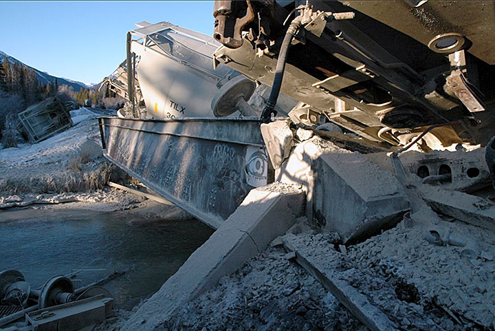
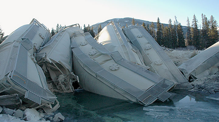
Fifteen cars derailed: 1 empty gondola, 9 covered hoppers loaded with fly ash, 1 covered hopper car of lentils, and 4 covered hopper cars loaded with soybeans. The trailing truck of the 39th car, DME 80060, was the first to derail. The 40th car and the 41st car remained upright on the roadbed. The 42nd car came to rest on its side, west of the bridge on the south side of the track. The 43rd to the 48th cars came to rest, derailed in jackknife fashion on the bridge on top of the north girder (Photo 2 and Photo 3).
The 51st and 52nd cars came to rest on their side, on the south side of the track and east of the bridge, with the 51st car partially submerged. The last derailed car, the 53rd car, remained upright with the leading truck derailed (Figure 2).

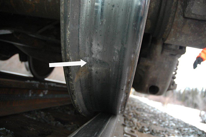
Impact marks on the wheel tread, consistent with contacting a broken rail, were present on some of the north wheels of cars on the head-end portion of the train which had not derailed. These impact marks were first observed on car 35, and became progressively more pronounced on cars 36, 37, and 38 (Photo 4).
The north sideframe of the lead truck on car 42 was damaged. Car 42 was the first car to contact the bridge. Although the bridge was equipped with inner guard rails,Footnote 4 the derailment had started approximately 240 feet east of the bridge and some of the derailed cars had jackknifed before reaching the guard rails.
The derailed cars were visually examined at the accident site. No pre-derailment defects were observed on the cars.
Prior to reaching the derailment location, the train had travelled over 3 hot box detectors and dragging equipment detectors, with the last one at Mile 65.6 of the Laggan Subdivision. No hot box detector or dragging equipment detector alarms had been set off.
Track information
The Laggan Subdivision, which is part of CP's main corridor to the west coast, consists of a single main track that extends from Mile 0.0 (Calgary, Alberta) to Mile 136.6 (Field, British Columbia). Train movements are governed by the centralized traffic control (CTC) system as authorized by the Canadian Rail Operating Rules and supervised by a rail traffic controller located in Calgary. The track is Class 3 according to the Transport Canada–approved Rules Respecting Track Safety (commonly called the track safety rules [TSR]). For Class 3 track, the maximum permissible track speed is 40 mph for freight trains. In 2013, traffic in the Laggan Subdivision was approximately 7.7 billion gross ton miles; it increased to 8.2 billion gross ton miles in 2014.
In the vicinity of the derailment, the main track consisted of 136-pound continuous welded rail manufactured in 2000. The rail was laid on 14-inch double-shouldered tie plates and was fastened to the hardwood ties with 3 spikes per tie plate. The ballast had a surface layer of crushed gravel and rock with 12-inch shoulders on a two-to-one slope. Ballast conditions and drainage were fair.
The switch was a No. 13 LH 136-pound RE dual control switch. The 22-foot long left hand Samson switch point was 2007 NKK head-hardened rail. The switch point, bent stock rail, and straight closure rail were connected at a five-hole heel block casting (Photo 5).

Track inspections and rail grinding
Turnout inspections are detailed in CP's Redbook of Track Requirements (Appendix A). Every turnout must be inspected monthly on foot in accordance with sections 15.3.2 and 15.6.0. A detailed inspection of the turnout must be conducted on foot once per year in accordance with sections 15.3.3 and 15.7.0. Heel blocks, joints, and bolts must be inspected in accordance with section 15.7.9. Inspection records must be maintained according to section 15.5.0.
Regulatory inspections of the track must be conducted in accordance with the TSR. The most recent track inspection at this location had been performed on December 23rd. Monthly inspections and detailed inspections were conducted and documented in accordance with CP's Redbook of Track Requirements. No defects in the vicinity of the derailment had been noted on any of the recent inspections.
The most recent rail flaw detection test for the mainline and the siding was conducted on 11 December 2014. No exceptions were noted in the vicinity of the derailment. The most recent track evaluation car geometry test was conducted on 19 November 2014. Digital track recordingFootnote 5 was performed on 23 December 2014 and vehicle/track interactionFootnote 6 (VTI) was conducted on 24 December 2014. No defects were noted in the area of the switch during these inspections. The track evaluation car test on November 19 did, however, identify some non-actionable (i.e., minor) alignment and surface deviations that did not exceed Class 3 surface defect thresholds in the area of the switch.
The rail on the main track had been ground on 21 April 2014 and the switch had been ground on 17 October 2014.
Examination of the broken rail
The broken rail, including the broken heel block joint, was sent to the TSB laboratory for detailed examination. It was determined that wheel impact marks on the rail fragments indicated that the switch point failure had started from its east end (i.e., the heel block area) and propagated along the rail, breaking out piece by piece.
Three cracks in the heel block area of the switch point (A, B, C in Photo 6) exhibited flattened polished fracture surfaces consistent with pounding between the mating surfaces of the crack. Such a pounding occurs during the passage of trains when fragments remain in place for some time after the crack appears.

The direction of the chevron pattern on the fracture surface indicated that crack C started at the second bolt hole. Two other cracks, D and E in Photo 6, emanating from this bolt hole, had a fresh appearance, indicating that the rail fragments had quickly separated after these cracks appeared.
The fracture surfaces on the other fragments also had a fresh appearance, indicating that the rail fragments separated instantaneously. The 3 cracks (A, B, and C) in the heel area had likely appeared first. When fragment 1 and fragment 2 separated from the rail, some of the wheels on cars that did not derail struck the broken rail, resulting in the impact marks on the tread. Shortly thereafter, some wheels started to derail, initiating the derailment and resulting in additional rail fractures beyond the heel block joint area (Photo 6).
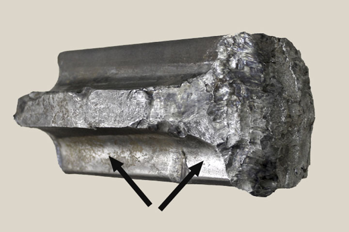
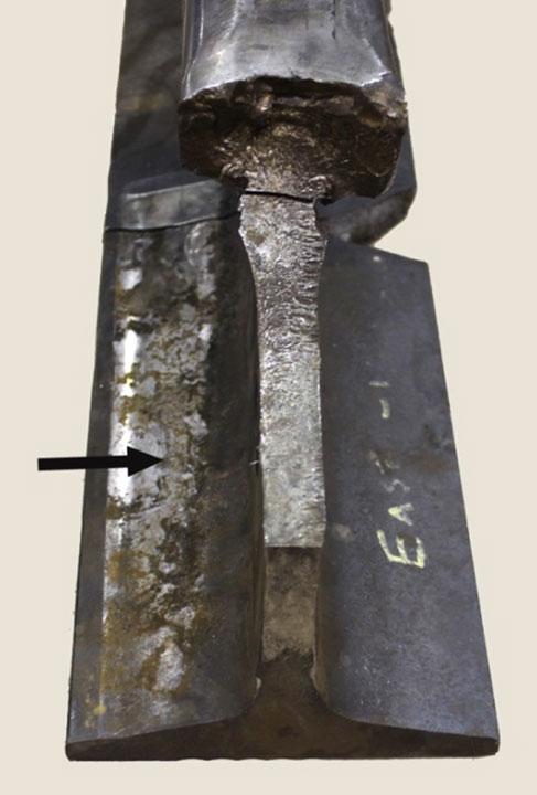
The fishing surfaces in the under-head fillets displayed metal-on-metal rubbing (burnishingFootnote 7) against the joint bar on the gauge side and against the heel block on the field (stock rail) side (Photo 7). The fishing surface on the rail base which was under the joint bar also exhibited rubbing (Photo 8). This rubbing was the result of relative movement of the heel components, indicating that there was some looseness in the joint.
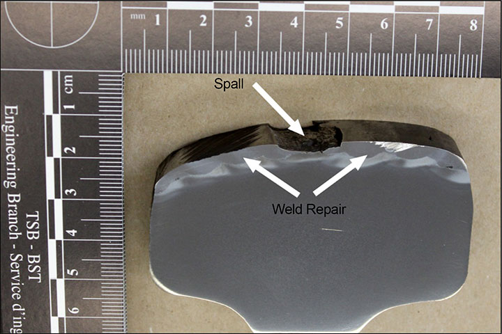
The running surface on the switch point rail had been weld-repaired in the vicinity of the heel block assembly. Spalling, as well as other smaller cracks,Footnote 8 had developed in the welded area (Photo 9).
The areas on the joint bar that were in contact with the fishing surfaces of the switch point (i.e., the north closure rail) exhibited burnishing, as well as localized extensive rub wear.
The intact components (stock rail, joint bars and heel block) had initially held the fractured pieces of the switch point in place for some time, allowing successive wheel impacts to further fragment the rail. The rail failure had started with a crack in the web, followed by the separation of the rail head.
Environmental impact and response
An incident command centre was established by CP at the occurrence site. The emergency responders included the RCMP, the Banff Fire Department, Parks Canada, Environment Canada, and the Alberta Ministry of Environment and Sustainable Resource Development.
A car containing soybeans had derailed into the creek with partial release of its load. Two of the 3 other derailed soybean cars had also breached, spilling their load on to the southeast bank and partially into the creek. During the response, the fourth derailed car containing soybeans was re-railed intact and removed from the scene.
The derailed fly ash cars on top of the bridge were mostly intact, except for one car which had been torn open, spilling some product into the creek. According to the Material Safety Data Sheet (MSDS) for the Boundary Dam Fly Ash (CAS #68131‐74‐8), the released material was a coal combustion by‐product from the Boundary Dam Power Station in Estevan, Saskatchewan. This product is used as an ingredient in the production of concrete. Its hazardous characteristics when released into the environment include high pH when wet, ability to smother sediment biota, and the presence of trace elements, including metals. This product is toxic by inhalation, and can cause skin and eye irritation. The conductor was not aware of these properties when inspecting the train.
The clean-up actions commenced shortly after the derailment. Much of the soybean product was successfully removed by vacuum truck.Footnote 9 During clean-up of the fly ash, the Banff Fire Department provided dust suppression by spraying water on the fly ash cars during wrecking operations. To minimize the spread of fly ash in the creek, a number of measures were taken at the derailment site and at other locations between the bridge over Forty Mile Creek and the confluence of this waterway with the Bow River. Specific mitigation measures included the installation of hay-bale sediment curtains and a rock wall lined with geotextile fabric.
The initial response actions were focused on clearing the wreckage from the track and making the derailment site safe, while minimizing the further release of fly ash into the creek to the extent practicable. During this clean-up, it was decided to remove the cars from the bridge by cutting them up. This activity however resulted in the further release of fly ash from the 7 cars that were on the bridge. The depth of fly ash in the creek sediment in the vicinity of the bridge was measured to be up to about 25 cm.
One of the railcars containing soybeans (Car 51) that had come to rest in the creek (with a partial release) was left in place pending additional data collection, ecological risk assessment, and remedial action planning. The car was removed from the creek on 19 March 2015. To determine the extent of environmental contamination and to remove fly ash from the stream, extensive in-stream sediment sampling and remediation activities were conducted in March and April 2015. These remediation efforts ceased in April 2015 due to the seasonal increase in stream flows. It is anticipated that environmental monitoring will continue for 3 to 5 years and additional remediation may be necessary.
Underground power systems
Canadian Pacific's summary bulletinFootnote 10 states (in part):
7200 VOLT UNDERGROUND POWER SYSTEMS
CPR has installed 7200 volt, underground power systems in the following areas:
- Laggan Sub Mile 82.10 (Banff West) to Mile 92.0 (Massive East)
- Laggan Sub Mile 116.5 (Lake Louise) to Mile 1 25.5 (Signal 1 252)
- Laggan Sub Mile 126.7 (Partridge East) to Mile 136.6 (Field)
- Mountain Sub. Mile 0.0 (field) to mile 0.6
Emergency brake application / equipment derailment
In case of emergency brake application in the vicinity of the buried power cable:
- Contact the RTC immediately and follow regular reporting practices
- Before dismounting from the locomotive, visually check to see if any cars within site have derailed
- If the derailed cars have dug into the ground in the vicinity of the cable (five to six feet off the end of the ties), then the crew should remain in the cab, not dismount, and they should notify the RTC
- If the cars immediately behind the locomotive have not derailed or have de-railed but have not likely cut the cable, then the train crew may dismount to carry out their inspection
- During the inspection, the train crew must not approach derailed equipment. The equipment may have partially severed the underground cable or damaged the electrical equipment, and disturbing the equipment could cause further harm.
[…]
Cable Location
The power cables are buried at a depth of 2 to 4 feet below the surface, generally 4 to 6 feet from the end of the ties. Along bridges, trestles and in tunnels, the cables are installed in ducts or troughing.
Cable Markers
Orange cable markers have been installed at key locations such as crossings, bridges, culverts, etc. They are offset from the actual cable trench.
System Safety
CAUTION: DO NOT approach or touch exposed cable or damaged electrical equipment until S&C personnel have confirmed, either directly or through the NMC, that the system has been de-energized and grounded.
In this occurrence, the conductor was not aware of the presence of the underground cable while performing the post derailment inspection of the train. An orange cable marker had been installed on both sides of the bridge. The locomotive engineer was aware of the underground cable, but he was not specifically aware of the hazards, or the recommended procedure for dealing with underground power systems in the vicinity of a derailment. The rail traffic control centre, in conversation with the crew subsequent to being notified of the derailment, provided no information concerning the presence of the underground cable system.
The cable was severed during the derailment. The power to the underground cable was terminated by the responding signal maintainer shortly after the initial post-derailment inspection was completed by the train crew.
Canadian Pacific's Train & Engine Safety Rule Book
The railway's Train & Engine Safety Rule Book includes the following requirements:
Emergencies and Derailments
- Follow all notification procedures as outlined in location-specific Emergency Response Plans.
- Approach an emergency or a derailment site only when it has been determined that it is safe to do so.
Job Briefing
Before performing any job, a job briefing led by the foreman/conductor must be held to ensure that all employees involved have a clear understanding of:
- The task to be performed;
- Your individual responsibility; and
- Situational awareness concerns
Additional verbal job briefings must be carried out as necessary, while the work progresses or as the situation changes.
Safe Work Procedure: Job Briefings
Crew members must ensure they are aware of conditions that will affect the safe operation of movements. Employees must:
- Ensure all operating bulletins and notices are read and understood;Footnote 11
TSB laboratory reports
The TSB completed the following laboratory report in support of this investigation:
- LP015/2015, Broken Switch Point, CP Train, 205-25
Analysis
No defective equipment wa s identified and no exceptions were noted in the manner the train was operated.
The analysis will focus on the condition of the heel block joint at the switch, track inspection and maintenance, job briefings, and the presence of the underground power system.
The accident
The train derailed when the end of the north switch point rail fractured in the heel block assembly. The heel block assembly had been weakened due to looseness in the joint, which had been occurring over time under train traffic. With the resulting relative movement in the joint, cracks developed in the switch point rail in the heel block. The rail fragments remained in place for some time after the initial cracks appeared, allowing successive wheel impacts to further fragment the rail. When the switch point rail in the heel block assembly finally failed under the occurrence train, the cracks propagated along the heel of the switch point rail, breaking it out piece by piece.
Track inspection in the vicinity of the switch
At the time of the occurrence, there were no actionable track geometry defects present in the vicinity of the switch. Although the track was maintained to Class 3 regulatory standards, there were non-actionable (i.e., minor) surface and alignment deviations at this location, contributing to inadequate joint support, movement, looseness of the joint, and breakage of the heel of the switch point rail. Although performed in compliance with regulatory and railway requirements, the regular monthly, detailed, and visual track inspections did not specifically note the deteriorating condition of the heel block assembly. If loose joints cannot be identified in a timely manner, particularly in the vicinity of switches (i.e., the heel block area), the resulting relative movement in the joint will increase over time, increasing the risk of cracks developing in the rail that will lead to broken-rail derailments.
Rail maintenance in the vicinity of the switch
The running surface of the switch point rail in the area of the heel block joint had been welded some time prior to the track failure in an attempt to lift the joint. Although this was an acceptable repair option, low joint surface conditions are normally corrected by tamping and lifting the joint.
Emergency response
The clean-up actions commenced shortly after the derailment. The initial response actions were focused on clearing the wreckage, ensuring that the derailment site was safe, and minimizing further environmental damage due to product release. Specific mitigation measures included the installation of hay-bale sediment curtains and a rock wall lined with geotextile fabric. The removal of wreckage and the restoration of railway operations were effective and efficient, but the release of fly ash during this process required ongoing site cleanup and remediation.
Underground power system hazard at the derailment site
The high-voltage underground cable in the vicinity of the derailment location was listed in the special instructions for the Laggan Subdivision. The railway was quick to cut the power after the derailment.
However, in the immediate aftermath of the derailment, in which the cable was severed, neither the train crew nor the rail traffic controller / director of train operations specifically took the presence of this hazard into consideration. Although the cable was not exposed, the indicator of its presence (an orange cable marker) was not sufficiently compelling to draw the attention of the crew members to the presence of the cable before they conducted their post-derailment inspection.
If there are underground power cables in the vicinity of a derailment site and this hazard is not considered, derailment site inspections and remediation may start before power is shut down safely, increasing the risk of injury to train crew members and other emergency responders.
Post derailment inspection and job briefings
Canadian Pacific's Train & Engine Safety Rule Book contains specific guidance for employees tasked with conducting post-derailment inspections.Footnote 12 Employees are to follow established notification procedures and are not to approach the derailment site until it has been determined to be safe to do so. Specific instructions are also provided to crews on the conduct of job briefings and the need for additional briefing whenever the circumstances change and new potential hazards emerge.
Although it is often not immediately apparent that a derailment has occurred, it is always a possibility when there is a train-initiated emergency brake application. In this occurrence, when the train came to an emergency stop, the crew began the train inspection process without discussing potential hazards, including those posed by the commodities carried.
A conversation with the RTC during the inspection did not include reference to the underground power system and the potential danger it represented. The railway summary bulletins for the Laggan Subdivision provided details about the underground power system at this location, and the safety actions and job briefings required in the event of an emergency brake application. Nonetheless, there was no discussion between the crew members—or among the crew members and the RTC—concerning the hazards associated with the underground power system before or during the train inspection.
If crew members or crew members and the RTC do not discuss hazards associated with the commodities carried or other features of the train or the railway infrastructure, such as an underground power system, before or during an inspection of derailed cars, there is increased risk of physical injury or death to crew members and other emergency responders.
Findings
Findings as to causes and contributing factors
- The train derailed when the end of the north switch point rail fractured in the heel block assembly.
- The heel block assembly had been weakened due to looseness in the joint, which had been occurring under train traffic over time.
- Although the track was maintained to Class 3 regulatory standards, there were non-actionable (i.e., minor) surface and alignment deviations at this location, contributing to inadequate joint support, movement, looseness of the joint, and breakage of the heel of the switch point rail.
- The rail fragments had remained in place for some time after the initial cracks appeared, allowing successive wheel impacts to further fragment the rail.
- When the switch point rail in the heel block assembly finally failed under the occurrence train, the cracks propagated along the heel of the switch point rail, breaking it out piece by piece.
- Although performed in compliance with regulatory and railway requirements, the regular monthly, detailed, and visual track inspections did not specifically identify the deteriorating condition of the heel block assembly.
Findings as to risk
- If loose joints cannot be identified in a timely manner, particularly in the vicinity of switches (i.e., the heel block area), the resulting relative movement in the joint will increase over time, increasing the risk of cracks developing in the rail that will lead to broken-rail derailments.
- If there are underground power cables in the vicinity of a derailment site and this hazard is not considered, derailment site inspections and remediation work may start before power is safely shut down, increasing the risk of injury to train crew members and other emergency responders.
- If crew members or crew members and the rail traffic controller do not discuss hazards associated with the commodities carried or other features of the train or the railway infrastructure, such as an underground power system, before or during an inspection of derailed cars, there is increased risk of physical injury or death to crew members and other emergency responders.
Other findings
- The removal of wreckage and the restoration of railway operations were effective and efficient, but the release of fly ash during this process required ongoing site cleanup and remediation.
- Although the weld repair on the running surface of the switch point rail was an acceptable repair option, track conditions involving low joints are normally addressed through tamping and lifting the joint.
- Although the cable was not exposed, the indicator of its presence (an orange cable marker) was not sufficiently compelling to draw the attention of the crew members to the presence of the cable before they conducted their post-derailment inspection.
Safety action
Safety action taken
Transport Canada requested that the railway industry formulate rules with regards to joint bar inspections and repairs in continuous welded rail territory.
This report concludes the Transportation Safety Board's investigation into this occurrence. The Board authorized the release of this report on 10 November 2015. It was officially released on 24 November 2015.
Appendices
Appendix A – Turnout inspection
Canadian Pacific's Redbook of Track Requirements provides guidance for conducting turnout inspections.
Section 15.3.2 (a) states (in part):
Except in the case of track that is used less than once a month, every turnout must be inspected once per month on foot. Monthly turnout inspections must include the procedures detailed in Section 15.6.0.
Section 15.3.3 (a) states (in part):
All turnouts on main tracks, sidings and on Category 1 yard tracks in Canada must receive a detailed inspection on foot once per year.
Section 15.7.9 Heel Blocks states:
Check the assembly to ensure that the bearing of the switch point is correct in relation to the heel block, and to the bent joint bar.
Check the block assembly for broken bolts. Replace bolts where required and maintain in a tight condition.