Non-main-track runaway, collision and derailment
Canadian National Railway Company
Cut of cars and train A42241-29
Mile 0.0, Halton Subdivision
MacMillan Yard
Concord, Ontario
The Transportation Safety Board of Canada (TSB) investigated this occurrence for the purpose of advancing transportation safety. It is not the function of the Board to assign fault or determine civil or criminal liability. This report is not created for use in the context of legal, disciplinary or other proceedings. See Ownership and use of content. Masculine pronouns and position titles may be used to signify all genders to comply with the Canadian Transportation Accident Investigation and Safety Board Act (S.C. 1989, c. 3).
Summary
On 29 July 2015, at about 1330 Eastern Daylight Time, a cut of 91 mixed commodity freight cars uncoupled from the locomotives on the east pullback track in the Canadian National Railway Company MacMillan Yard. The cut of cars, led by 24 tank cars loaded with petroleum crude oil (UN 1267), rolled uncontrolled into track R-13 where it struck train A42241-29 (train 422) head on at about 13 mph. Although none of the cars in the cut of cars derailed, the head-end locomotives of train 422 were shoved back 350 feet, and 10 cars on that train derailed on track R-13. One car on adjacent track R-11 also derailed. The derailed equipment included an empty (residue) tank car that last contained sulphuric acid (UN 1830). A second car on track R-11 and 1 car on track R-10 were damaged. Approximately 585 feet of track was damaged. There was no release of product and there were no injuries.
1.0 Factual information
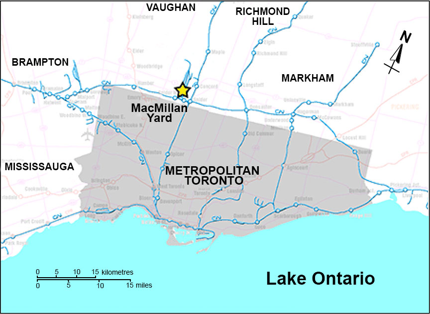
On 29 July 2015, Canadian National Railway Company (CN) MacMillan Yard Hump Assignment YDHF01 (the assignment) was switching in MacMillan Yard, located in Concord, Ontario, part of the Greater Toronto Area (Figure 1). The locomotive hump set, located at the head end of the assignment, consisted of 2 locomotives separated by 2 booster units. They were ready to pull 91 cars (64 loaded cars and 27 empty cars) onto the hump pullback track in preparation for humping. The assignment was about 6100 feet long, weighed about 9000 tons and was being controlled by a single conductor operating a remote control locomotive system (RCLS) known as a Beltpack.Footnote 1 The conductor was familiar with yard operations, met fitness and rest standards, and was qualified for the position.
The 1st car coupled to the trailing assignment locomotive (CN 7506) at the north end of the movement was an empty 89-foot-long flat car (CN 44257). At the south end of the assignment, the 68th car to the 91st car (24 cars) were DOT-111Footnote 2 general service tank cars loaded with petroleum crude oil (UN 1267) destined for Irving Oil in Saint John, New Brunswick. These tank cars were built to comply with the Association of American Railroads (AAR) CPC-1232 standard. With the exception of the 74th tank car from the head end (TILX 281284), the tank cars located at the south end of the movement were jacketed and insulated.
CN train A42241-29 (train 422) was an eastbound key trainFootnote 3 that arrived at MacMillan Yard on the Halton Subdivision from Port Robinson, Ontario. Upon arrival, it remained on the inbound track while waiting to access the receiving yard. Train 422 was equipped with 2 head-end locomotives and was hauling 50 loaded cars and 131 empty cars. It was about 11 400 feet long and weighed 10 200 tons. The head-end 27 cars included 4 loaded cars and 23 empty cars. Six (6) of the empty cars were located within the first 8 cars behind the locomotives. The crew of train 422 consisted of a locomotive engineer and a conductor. They were familiar with the territory, met fitness and rest standards, and were qualified for their respective positions.
1.1 The accident
At about 1319,Footnote 4 the hump assignment attempted to couple onto the 1st car (CN 44257) of a cut of 91 mixed commodity freight cars (cut of cars) on track R-13 of the receiving yard, but was unsuccessful. About a minute later, the assignment successfully coupled onto the cut of cars. After observing the coupling from a position on the ground, the conductor then stretched the movement and began pulling the cut of cars northward onto the east pullback lead track. As was normal practice, the air brakes on the cut of cars had been previously discharged, leaving only the locomotive brakes to control the assignment.
As the assignment pulled out of the north end of track R-13, the yardmaster authorized train 422 to pull into track R-13 from the south end. The conductor remained on the ground. While walking to the base of the hump, the conductor inspected the cars on the assignment as they passed by. From the base of the hump, the conductor continued to observe the assignment as the cars travelled up the east pullback lead track and onto the east pullback track.
At about 1325, after about 60 cars had passed, the conductor noticed that the movement had begun to slow unexpectedly. Using the Beltpack, the conductor queried the locomotive status and applied sand to the locomotive wheels. The RCLS had not reported any problems. As the cars continued to slow, the conductor made another status query using the Beltpack. The conductor then called the yardmaster and reported a suspected train separation. At about this time, the cars coasted to a stop.
At 1327:10, the cut of cars began to roll uncontrolled in reverse back into track R-13, led by the 24 tank cars loaded with petroleum crude oil.
At 1328, the yardmaster alerted the crew of train 422 that an uncontrolled movement was headed toward them. The crew brought train 422 to a controlled stop, set the air brakes and detrained to a position west of track R-16. A CN yard video camera recorded the subsequent events.
At 1331:27, the yardmaster warned mechanical personnel, who were working on tracks R-19 and R-25, that a cut of cars was going to collide with train 422 on track R-13. As the cut of cars approached, the crew of train 422 walked back to within about 20 feet of the lead locomotive.
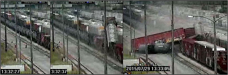
At 1332:29, the south end of the uncontrolled cut of cars collided head on with train 422 (Figure 2), as the crew of train 422 quickly evacuated the area.
There were no injuries and there was no release of product.
At the time of the accident, the weather was clear with a temperature of about 32 °C and a 12 km/h wind from the northeast.
1.2 Site examination
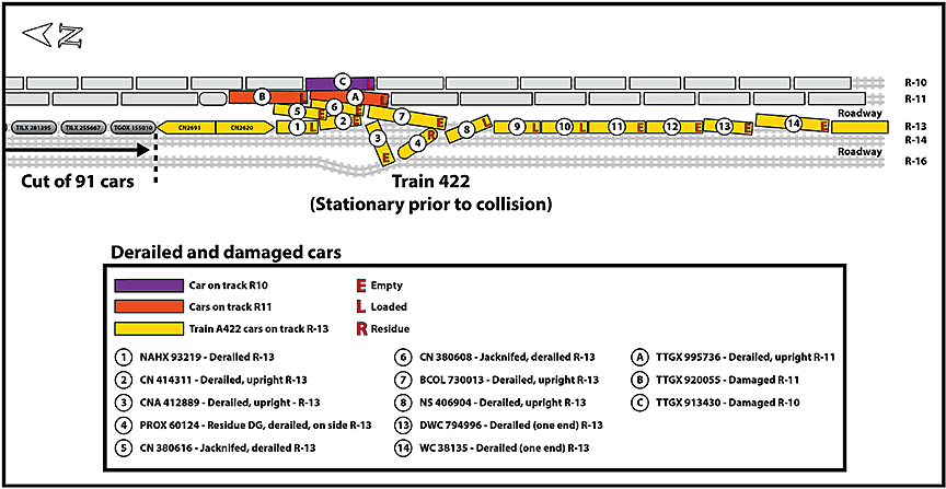
The collision occurred about 5900 feet south of switch 18. The force of the collision shoved both head-end locomotives on train 422 about 350 feet back onto its consist, resulting in the derailment of the 1st to 8th cars and the 13th and 14th cars behind the locomotives. The 3rd car (empty box car CNA 412889) diverged westward across track R-14 and a roadway, and displaced 60 feet of track R-16. The 5th and 6th cars (empty covered hopper cars CN 380616 and CN 380508) jackknifed vertically and then fell eastward and struck 2 loaded multi-level auto carrier cars (TTGX 920055 [damaged] and TTGX 995736 [damaged and derailed]) that were stationary on adjacent track R-11. Multi-level auto carrier car TTGX 913430 on track R‑10 was also damaged. Six freight cars were destroyed. Approximately 585 feet (180 m) of track from tracks R-13, R-14 and R-16 was damaged (Figure 3). None of the cars of the uncontrolled cut of cars derailed.
The lead car on the uncontrolled cut of cars (i.e., the 91st car from the head end of the assignment) was tank car TGOX 155010. A post-collision visual inspection of the cut of cars was conducted by CN mechanical personnel. No safety defects were observed and none of the tank cars were leaking. Subsequently, the freight cars, including the tank cars containing dangerous goods (DG), were returned to service and transported to their respective destinations. No further action was taken by CN at that time.
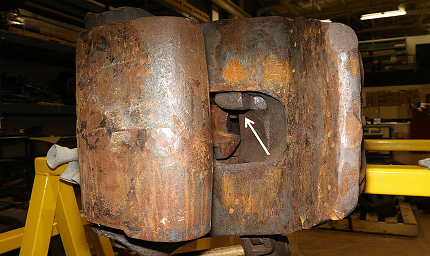
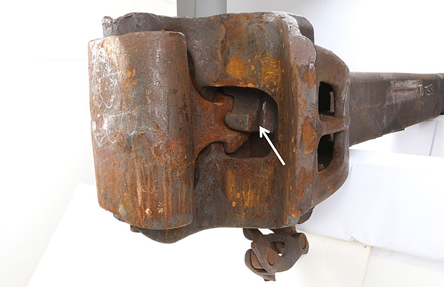
At the north end of the assignment, the cut of cars had separated from the trailing locomotive (CN 7506). The knuckle on the trailing locomotive had remained closed and locked, but the adjoining knuckle on the B-end of flat car CN 44257 had opened. The coupler assemblies from locomotive CN 7506 and flat car CN 44257 were removed and sent to the TSB Engineering Laboratory for detailed examination.
During a subsequent examination of the pullback tracks, various broken and rusted coupler and knuckle components were observed along the tracks. It is not known how long these components had been there.
1.3 Recorded information
The collision was captured on a video camera that had been installed at CN MacMillan Yard. TSB laboratory analysis of the video recording determined that the uncontrolled cut of 91 cars was travelling at about 13 mph when it collided with train 422.
Table 1 provides a summary of the sequence of events. These events were compiled based on the yard camera video recording, the locomotive event recorder (LER) and the video recorder on train 422, the Beltpack event records, and various audio recordings.
| Time | Activity |
|---|---|
| 1207 | Train 422 arrived at MacMillan Yard. |
| 1318:52 | The assignment unsuccessfully attempted to couple to the cut of cars (CN 44257) on track R-13. |
| 1319:52 | The hump assignment coupled to the cut of cars (CN 44257) on track R-13. |
| 1320:14 | The conductor stretched the coupling, requested 4 mph, and the assignment began to move northward out of track R-13. |
| 1320:22 | The yardmaster authorized train 422 to pull into R-13 from the south. |
| 1322:28 | The head end of the assignment entered the east pullback track at a speed of 14.7 mph. |
| 1323:36 | Train 422 started to pull into R-13 from the south. |
| 1325 | The assignment experienced wheel slip as more of the movement proceeded onto the grade of the east pullback track. Note: Wheel slip is recorded on the Beltpack event recorder, but the information is not available or displayed to the RCLS operator (conductor). |
| 1325:14 | The assignment's last recorded wheel slip. |
| 1325:47 | The conductor initiated a sand request. |
| 1325:53 | The cut of cars separated from the assignment while travelling northward at about 13 mph. The hump assignment continued to proceed up the east pullback track with speed limited by the pullback computer system. At the same time, the conductor requested status of the movement from the Beltpack unit and received a message indicating that the locomotive was operating normally. |
| 1326:20 | The conductor made another status request. |
| 1327:10 | The cut of 91 cars slowed to a stop with about 4700 feet on the east pullback track north of switch 18 and about 1400 feet south of switch 18. |
| 1327:15 | The yardmaster used a yard camera to check the movement status as the cut of cars began to roll away uncontrolled. |
| 1328 | The yardmaster informed the crew of train 422 that a cut of 91 cars was rolling toward them uncontrolled. The crew of train 422 was instructed to stop the train and clear the area. |
| 1329 | A second warning was issued by the yardmaster. |
| 1331 | A 3rd call was placed to the crew of train 422 informing them that the cut of cars rolling uncontrolled toward them contained flammable liquids. |
| 1331:27 | Mechanical personnel working on tracks R-19 and R-25 were warned that a cut of cars was going to run into train 422 on track R-13. |
| 1331:30 | The crew of train 422 departed the lead locomotive and cleared upwind to the area west of track R-16. |
| 1332:15 | As rolling cars approached the standing train 422, the crew walked back to about 15 to 20 feet southwest of the point of impending collision. |
| 1332:29 | The leading car (91st) behind the assignment (loaded tank car TGOX 155010) collided with the lead locomotive of train 422 (CN 2691). The crew of train 422 quickly ran back to the area west of track R-16. |
| 1333:07 | All cars came to rest 38 seconds later. |
1.4 MacMillan Yard
MacMillan Yard is CN's main classification yard in Eastern Canada where rail traffic is distributed by flat switching or "humping"Footnote 5 rail cars into various tracks for placement on different trains. The yard has a north-south orientation (Figure 4).
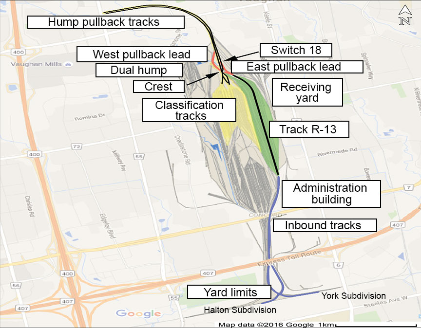
Arriving trains enter the yard from the York Subdivision or the Halton Subdivision at the south end of the lower yard. The trains are routed up the inbound tracks on the east side of the yard. When the yard is congested, arriving trains wait on the inbound tracks for an empty track in the receiving yard, located east of the main classification yard. Once the cars are set out in a receiving yard, the locomotives are removed, the rail cars are inspected, and the air brake system is discharged to empty. The cars are then flat-switched or humped to redistribute the cars onto different trains for various destinations.
The hump yard consists of 2 pullback tracks (east and west), a lead track to each pullback track from the receiving yard, a hump with retarders, and classification tracks. Neither pullback lead track is equipped with inert retarders, which are used to slow cars to manage speed during humping operations, as freight cars are not humped into the receiving yard. For a movement that is pulled northward onto the hump pullback tracks from the receiving yard, there is no protection against an uncontrolled movement caused by an unplanned train separation until the movement is north of and clear of switch 18.
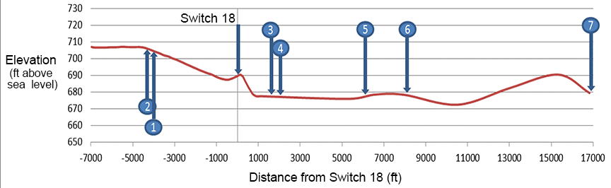
The top of the east hump pullback track at the north end of MacMillan Yard has the highest elevation of the yard (at about 710 feet above sea level). From this point, it descends southward at a maximum grade of about 0.5% toward switch 18. The east pullback lead track joins the east pullback track at switch 18. South of switch 18, the east pullback lead track descends southward for about 800 feet with an average grade of 2.5%. Southward from this point, it transitions to a shallow descending grade.
1.5 Humping operations
Approximately 2000 freight cars per day are humped at CN MacMillan Yard and about 200 of these cars (10%) are DG tank cars. Humping operations are controlled by the hump process control system, which determines routing through the yard and controls the speed of the cars as they travel to their designated classification track. Once rail cars are released from the hump, their speed is automatically controlledFootnote 6 at 2 locations, which include a master retarder and a group retarder.Footnote 7
A computer system calculates car speed and predicts rollability based on wind speed and direction, temperature, precipitation, rail car type and weight, and distance to coupling (DTC). After a rail car exits the master retarder, its speed is measured by radar and wheel sensors. Speed is further adjusted at the group retarder. Once the rail car leaves the group retarder, there are no other locations to adjust speed before it reaches the intended coupling location.
DTC is calculated by monitoring the change in frequency of an electric current (circuit) as the rail car rolls along the classification track. By establishing the location of the rail car and knowing the length of the track and the number of stationary rail cars already on the track, the remaining distance and coupling speed can be estimated.
The speed of a car is based on predictive analytics that the computer monitors through measurements that include weight, wind speed and direction, speed at fixed locations (such as exit of retarders), DTC, and car rollability. The system is not a precise means of measurement as the accuracy of the DTC value can be affected by conditions that include
- car rollability, which can change based on rail contamination;
- variances in stiffness of trucks through turnouts;
- the number of turnouts traversed;
- wheel friction based on profile of wheel and rail;
- changes in wind speed and orientation relative to freight car aerodynamics; and
- multiple cars in the same measuring zone as 2 or more moving cars within a track or coupling zone creating blind spots that computer logic cannot overcome.
There is currently no accurate method to determine actual coupling speed during humping operations.
1.5.1 MacMillan Yard
When pulling cars to the pullback tracks, a conductor does not ride the movement. The conductor must observe equipment from the ground, checking for conditions that could have an impact on humping operations such as dragging equipment, skidding wheels, or improperly secured doors and lading. If a condition is found, the conductor must alert the yardmaster and, if necessary, stop the movement.Footnote 8
To help ensure that cars are handled safely during yard operations, section 5.17 of the MacMillan Yard Operation Manual deals with pull-aparts and states
Employees are to exercise caution when pulling tracks northward over the crest. Employees MUST be in position at the crest to watch for pull-aparts and are to inform the Traffic Coordinator immediately upon discovery of such an occurrence.
Pull-aparts (train separations) occasionally occur during pullback operations. In MacMillan Yard, if a train separation occurs before the cars clear the pullback lead tracks, the cars that separate can roll uncontrolled southward back into the yard depending on how the switches are aligned at the time. When a train separation occurs, it is often identified immediately and the cars are secured without further incident. CN has no internal requirement for reporting unplanned train separation events in the yard if there has been no collision, derailment, or secondary consequence.
1.6 Coupling to equipment
Coupling equipment together must be performed according to Rule 113 of the Canadian Rail Operating Rules.(CROR) and according to sections 3.5, 8 and 12.10 of the CN General Operating Instructions (GOI). These requirements include
- Coupling made using the RCLS must be made at a speed not exceeding 1 mph.Footnote 9
- Cars must be stretched following coupling to ensure a successful joint was achieved.Footnote 10
- If the coupling is made on other than tangent track, the cars must first be stopped not less than 6 and not greater than 12 feet apart to ensure that the couplers are properly aligned.Footnote 11
At CN, operations personnel are instructed to look for proper alignment of the bottom-operated lock-lift assembly pivot points (toggles) when monitoring a joint to ensure that the coupler locking block has dropped properly into place to secure the knuckle (see figures in Section 4.1.1).
CN conductors are regularly efficiency-tested on couplingFootnote 12 to ensure compliance. In the 12 months preceding this occurrence, the conductor had been efficiency-tested 53 times covering 89 rules, and had 6 non-compliances. Eight of the 53 tests were focused on coupling to equipment, on which the conductor achieved a 100% pass rate.
1.7 Track information
MacMillan Yard operations are conducted under CROR Rule 105. Train movements are restricted to speeds of up to 15 mph and must be able to stop within half the range of vision.
Track R-13 is in the receiving yard, east of the classification track. This track is mainly tangent and is oriented in a north-south direction. The track consists of 130-pound head-free jointed rail. The rail was laid on single-shouldered tie plates secured to number 1 hardwood ties and box-anchored every third tie. The ballast was crushed rock and the cribs were full. The track was in good condition.
Yards are generally designed with a bowl-shaped profile to protect against freight cars rolling uncontrolled onto the main track during switching and/or humping operations. MacMillan Yard has a descending grade from both the north and south end of the tracks toward the centre of the yard, giving it a bowl-shaped profile.
A survey of the east pullback track, the east pullback lead track, track R-13, and the track up to and exiting the yard was reviewed. Using switch 18 as "zero," various critical points related to the accident were measured. The resulting track profile (Figure 5) graphically illustrates the yard elevations, distances and critical points along the route of the uncontrolled cut of cars. The critical points coinciding with specific events or locations include
- Freight car CN 44257 and 90 trailing cars separated from the assignment.
- North end of the cut of 91 cars stopped before reversing down the descending grade.
- South end of the cut of 91 cars stopped about 4500 feet north of train 422.
- Northern limit of track R-13.
- Point of collision with train 422, about 5900 feet south of switch 18.
- Junction of track R-13 and the York 3 inbound track.
- Junction of York 3 inbound track and York Subdivision main track.
1.8 Transportation of Dangerous Goods Regulations
In 1997, the National Research Council of Canada (NRC) conducted testsFootnote 13 to identify the maximum speed at which DG tank cars can be coupled without exceeding 1 000 000 pound-force, which corresponds to the AAR minimum longitudinal force specification for tank cars.Footnote 14
In 2002, the results of the NRC tests were incorporated into section 10.7 – Coupling of Railway Vehicles of the Transport Canada (TC) Transportation of Dangerous Goods Regulations.(TDG Regulations). Section 10.7 applies to rail cars transporting a regulated substance.Footnote 15 The speeds referenced in this section are based on actual coupling speeds.
1.8.1 Section 10.7 of the Transportation of Dangerous Goods Regulations
Section 10.7 of the TDG Regulations states (in part)
- A person must not couple a railway vehicle with another railway vehicle at a relative coupling speed greater than 9.6 km/h (6 mph) if either of the railway vehicles that make contact on coupling contains dangerous goods for which a placard is required to be displayed in accordance with Part 4, Dangerous Goods Safety Marks.
- Despite subsection (1), a person may couple a single railway vehicle moving under its own momentum at a relative coupling speed less than or equal to 12 km/h (7.5 mph) when the ambient temperature is above -25°C.
- If a person couples a tank car that contains dangerous goods for which a placard is required to be displayed in accordance with Part 4, Dangerous Goods Safety Marks, with another railway vehicle and the three conditions in any one of the four rows set out in the table to this subsection apply, the person must
- visually inspect the underframe assembly and coupling and cushioning components of the tank car to ensure their integrity before the tank car is moved more than 2 km from the place where the coupling occurred; and
- report, in writing, to the owner of the tank car within 10 days after the coupling and include a copy of the text of this section and information about any damage that compromises the integrity of the underframe assembly or draft gear of the tank car discovered as a result of the inspection.
Item Column 1
Combined Coupling Mass: Tank Car and Other Railway Vehicle, and their Contents, in KilogramsColumn 2
Ambient Temperature: in Degrees CelsiusColumn 3
Relative Coupling Speed: in Kilometres per hour1. > 150 000 ≤ -25 > 9.6 2. > 150 000 > -25 > 12 3. ≤ 150 000 ≤ -25 > 12.9 4. ≤ 150 000 > -25 > 15.3
- The owner of a tank car who receives the report must not use the tank car or permit the tank car to be used to transport dangerous goods, other than the dangerous goods that were contained in the tank car at the time of the coupling, until the tank car undergoes
- a visual inspection and a structural integrity inspection in accordance with clause 9.5.6(a) and clause 9.5.7 of TP14877; and
- for a tank car equipped with a stub sill, a stub sill inspection covering at least the following areas:
- the termination of the stub sill reinforcement pad closest to the mid-point of the tank car and associated welds for a 30-cm length from that point back towards the other end of the pad,
- all welds
- connecting the head brace to the stub sill,
- between the head brace and the head reinforcement pad, and
- between the tank and the head reinforcement pad and, if the head reinforcement pad is connected to the stub sill reinforcement pad, 2.5 cm past that connection towards the centre of the tank,
- all metal of the stub sill assembly, other than welds, from the body bolster to the coupler, and
- the draft gear pocket.
- This section does not apply if either the tank car or the other railway vehicle that was coupled is equipped with a cushioning device designed for a displacement of 15 cm or more in compression and capable of limiting the maximum coupler force to 453 600 kg when impacted at 16.1 km/h (10 mph) by a railway vehicle having a gross mass of 99 792 kg.Footnote 16
The regulations do not require railways to measure coupling speeds or to document suspected over-speed couplings. The regulations require that a visual inspection be conducted following a suspected over-speed coupling involving a DG tank car. However, for jacketed tank cars, the stub sill and underframe assembly cannot be visually inspected thoroughly unless portions of the jacket are removed.
1.8.2 Safety Standard TP 14877, Containers for Transport of Dangerous Goods by Rail
Safety Standard TP 14877, Containers for Transport of Dangerous Goods by Rail, is incorporated into the TDG Regulations by reference. Clause 9.5.6 of TP 14877 states
9.5.6 Visual Inspection
At a minimum, the visual inspection performed under this section must include the following items for the purpose of detecting defects or other conditions that could compromise the reliability of the tank car:
- Subject to clause 9.5.6 i., the interior and exterior surface of the tank car tank, except in areas where an insulation system, a safety system, or an internal lining or coating precludes inspection;
Clause 9.5.7 of TP 14877 states
9.5.7 Structural Integrity Inspection
- 9.5.7.1 The structural integrity inspection must be performed by using one or more of the non-destructive evaluation methods set out in Table T2 of the AAR Specifications for Tank Cars publication.
- 9.5.7.2 At a minimum, the structural integrity inspection must include all of the locations susceptible to damage that could compromise the reliability of the tank car tank, nozzles, welds, and welded attachments, including:
- all transverse fillet welds with dimensions greater than 6 mm (¼ in.) within 122 cm (4 ft.) of the bottom longitudinal centreline, except body bolster pad attachment welds;
- the termination of longitudinal fillet welds with dimensions greater than 6 mm (¼ in.) within 122 cm (4 ft.) of the bottom longitudinal centreline; and
- the tank shell butt welds within 60 cm (2 ft.) of the bottom longitudinal centreline unless the tank car owner can determine by analysis, such as damage tolerance analysis and finite element stress analysis that the tank car will not develop defects or other conditions that could compromise its reliability. The analysis must include a determination of the probable locations and modes of damage to the tank car due to fatigue, corrosion, or accidental damage. As an alternative, service reliability assessment may be used, provided it is supported by analysis of systematically collected data.
- 9.5.7.3 For a Specification 115 tank car, clause 9.5.7.2 applies only to the outer shell fillet welds and to the non-reinforced, exposed, outer shell butt welds.
- 9.5.7.4 In the case of tank cars with a lining, the inspection requirements of clause 9.5.7.2 c. do not apply to a tank shell butt weld covered on the outside by a reinforcing plate or any other structural element welded to the tank shell until the time of lining removal or application.
- 9.5.7.5 In the case of a tank car with an internal patch plate, the structural integrity inspection requirements of this paragraph do not apply to a tank shell butt weld covered on the inside by the patch plate and on the outside by a reinforcing plate or any other structural element welded to the tank shell.
1.9 Further follow-up with the tank cars involved in the collision
Shortly after the occurrence, a visual inspection of the tank cars involved in the collision was conducted by CN at the occurrence site. With no safety defects observed and no tank cars leaking, the tank cars were returned to service and allowed to transport their product to their respective destinations. About one week later, on 04 August 2015, CN was informed that the uncontrolled cut of 91 cars had been travelling at about 13 mph at the time of the collision. Due to the speed and magnitude of the collision, some of the jacketed tank cars positioned at the south end of the cut of cars required further inspection.
The tank cars had already been sent to destination. After the tank cars containing crude oil were offloaded by Irving Oil, the TSB requested that the first 10 tank cars at the south end of the movement (82nd to 91st inclusive) be sent to Moncton, New Brunswick, and held until further notice.
The 91st car (TGOX 155010), which struck the lead locomotive of train 422, the 90th car (TILX 255667), and the 89th car (TILX 281395) were selected for more detailed stub sill and integrity inspections. While the uncontrolled movement was not intended to couple with train 422, given the speed at which the collision involving tank cars loaded with DG occurred, it was determined that inspections would be conducted in accordance with inspection criteria set forth in section 10.7 of the TDG Regulations. The 3 tank cars were forwarded to ARI Fleet Services of Canada in Sarnia, Ontario, for inspection while the 7 other tank cars remained in Moncton pending results of the inspections.
On 21 August 2015, CN reported to the owners of the 3 tank cars (91st to 89th) that the cars had likely experienced an over-speed coupling event.
On 05 October 2015, TSB investigators visually inspected the 7 tank cars that remained in Moncton. These tank cars were the 4th to 10th cars from the point of contact between the cut of cars and train 422. All of the subject cars were relatively new, having been built between 2012 and 2014. The follow-up examination focused on identifying any signs of over-speed couplings such as
- contact between the coupler horns and strikers at each end;
- by-passed couplers;
- stub sills bent or bulged;
- damage to the front and rear draft gear lugs;
- broken/damaged draft gears, couplers, yokes, and related parts; and
- previous repair work in these same areas.
There were no visible signs that any of the 7 tank cars had been subject to rough handling and/or over-speed couplings. In addition, there was no indication that the coupler horns on any of the 7 cars had made contact with the corresponding striker.
1.10 Canadian National Railway Company inspection of suspected tank car over-speed couplings
On 15 August 2002, CN had issued the following instructions:
- The hump supervisor must notify the on-duty transportation officer of any DG tank car involved in an over-speed couplingFootnote 17 due to humping or flat switching.
- The transportation officer must then report the incident to the mechanical department for follow-up inspection and reporting.
Before February 2015, there were no records of a formal process to document over-speed coupling events involving DG tank cars in MacMillan Yard.
In February 2015, CN implemented a new protocol for inspecting and documenting suspected over-speed couplings that occurred during humping operations in MacMillan Yard. When an over-speed coupling involving a DG tank car occurs during humping operations, the following protocol is to be followed:
- CN mechanical would receive an automated email alert.
- For most of the email alert categories, both cars involved in the over-speed coupling would be bad-ordered automatically in the CN mechanical system.
- A CN mechanical employee would inspect the cars on outbound trains.
- Subsequently, tank cars would either be coded to remain in bad-ordered status or would be released from bad-ordered status based on a visual inspection.
For flat switching, there is no similar protocol for inspecting suspected tank car over-speed events. In addition, CN does not review locomotive event recorder downloads to review switching practices unless the suspected over-speed event involves a derailment or collision.
1.10.1 Canadian National Railway Company over-speed couplings in MacMillan Yard - 2015
Based on data available through CN's Special Car Handling Hazardous Commodity (SCH‑HC) alert system,Footnote 18 between February 2015 and December 2015:
- There were 279 over-speed couplings involving DG tank cars where the estimated coupling speed was 12 km/h (7.5 mph) or greater.
- These 279 over-speed coupling events involved a total of 448 DG tank carsFootnote 19 that were identified as either the hammer or the anvil.Footnote 20 In about 3% of the cases (13 out of 448), the owner of the tank car was notified of the over-speed coupling event and the tank car was sent for a stub sill inspection.
1.10.2 Canadian National Railway Company pilot project on potential over-speed couplings - 2016
In 2016, CN implemented a pilot project to determine if coupling speeds could be accurately captured within hump yards. Using the DTC speeds estimated by the hump system, CN identified 100 DG tank cars that had a potential coupling speed of greater than (>) 8 mph.
These cars were inspected by CN mechanical personnel and then sent to a tank car shop for a detailed inspection as required by section 10.7 of the TDG Regulations. A small number of these cars had minor external defects primarily related to coupler components. However, none of the 100 cars exhibited any damage to the stub sill, head brace or shell that could be associated with an over-speed coupling.
In early 2017, CN discussed the results of its pilot project with the TC Transportation Dangerous Goods (TDG) Directorate. CN indicated that while section 10.7 of the TDG Regulations has a requirement to take action on over-speed couplings, there was no way to capture accurate coupling speeds.
To date, the TDG Directorate has not issued any waiver or exemption relieving CN of its responsibility to comply with section 10.7 of the TDG Regulations.
1.11 Transport Canada enforcement of the Transportation of Dangerous Goods Regulations
Section 10.7 of the TDG Regulations is based on actual coupling speeds. TC does not consider speeds that have been calculated using the railway DTC system as actual, enforceable speed readings. For hump operations, railways do not have any systems that can measure actual coupling speed.
The TDG Directorate had not issued to CN any inspections, notices or orders, or exemptions with regards to over-speed couplings or with compliance to section 10.7 of the TDG Regulations during humping and switching operations in MacMillan Yard.
In 2003, the TSB investigated an over-speed collision in MacMillan Yard (TSB Railway Investigation Report R03T0047). The investigation identified that
- TC TDG inspectors had not been instructed on how to measure the railway's compliance with coupling speed regulations.
- TC TDG inspectors were unsure how the railway could reasonably comply with the coupling regulations, but were satisfied that a certain level of compliance does occur.
- TDG inspectors had assumed that the railways performed the required follow-up when potential over-speed couplings occur. However, the railways had not been audited to verify that the required follow-up occurred.
Due to safety concerns, the TDG Directorate indicated that radar guns should not be used for enforcement activities in the classification yard. However, it was recognized that, as written, with reliance on actual speed measurements and no requirement for railways to measure coupling speeds, broad industry application of section 10.7 of the TDG Regulations was not occurring and was difficult to enforce actively.
In addition, it was acknowledged that the safe-to-travel provisions of section 10.7 were less effective with respect to jacketed tank cars, as the jacket must be removed to visually inspect safety-critical areas of a stub sill car. As a result, compliance with section 10.7 of the TDG Regulations was not being consistently nor comprehensively audited.
1.12 Railway Safety Management System Regulations, 2015
On 01 April 2015, the Railway Safety Management System Regulations, 2015.(2015 SMS Regulations) came into force and replaced the 2001 SMS Regulations. The 2015 SMS Regulations responded to the recommendations from the 2007 Railway Safety Act Review and the 2008 study on rail safety by the Standing Committee on Transport, Infrastructure and Communities (SCOTIC), which were intended to improve the effectiveness of railway safety management systems (SMS).
Under these regulations, federal railway companies must develop and implement an SMS, create an index of all required processes, keep records, notify the Minister of proposed changes to their operations, and file SMS documentation with the Minister when requested.
Section 5 of the SMS Regulations states
A railway company must develop and implement a safety management system that includes
- a process for accountability;
- a process with respect to a safety policy;
- a process for ensuring compliance with regulations, rules and other instruments;
- a process for managing railway occurrences;
- a process for identifying safety concerns;
- a risk assessment process;
- a process for implementing and evaluating remedial action;
- a process for establishing targets and developing initiatives;
- a process for reporting contraventions and safety hazards;
- a process for managing knowledge;
- a process with respect to scheduling; and
- a process for continual improvement of the safety management system.
Item (e) of the SMS Regulations states
Process for Identifying Safety Concerns
Analyses
- A railway company must, on a continual basis, conduct analyses of its railway operations to identify safety concerns, including any trends, any emerging trends or any repetitive situations. The analyses must, at a minimum, be based on
- any reports of railway occurrences;
- any internal documentation relating to railway occurrences;
- any reports of injuries;
- the results of any inspections conducted by the railway company or by a railway safety inspector;
- any reports of contraventions or safety hazards that are received by the railway company from its employees;
- any complaints relating to safety that are received by the railway company;
- any data from safety monitoring technologies;
- the conclusions of the annual report referred to in subsection 29(3); and
- the findings of any audit reports.
1.13 Canadian National Railway Company's safety management system
In accordance with the SMS Regulations, CN had developed and implemented a detailed SMS. Since 2008, CN's SMS had been enhanced each year and had been integrated into much of its operations. The SMS described company initiatives that correlate to the requirements of the SMS Regulations.
CN had implemented systems for
- identifying safety issues and concerns, including those associated with human factors, third-parties and significant changes to railway operations;
- evaluating and classifying risks by means of a risk assessment; and
- identifying and implementing risk control strategies.
Specific actions relating to its SMS included the following:
- Safety issues and concerns were flagged to CN management through hazard forms, health and safety committees, CN's Ombudsman and CN's Prevent Hotline (a joint venture with Saint Mary's University, Halifax, Nova Scotia), as well as through audits and trend analyses.
- CN had a formal risk assessment process that was used to evaluate and classify risks, including those associated with significant changes in railway operations, such as the opening of new yards and facilities, railway acquisitions, introduction of new technology, significant changes in business (volumes or product), and changes in personal protective equipment.
- Special corridor risk assessments were being carried out to assess and reduce risk in locations with high populations, waterways, or other environmental or topographical characteristics.
- Training was being provided to employees who performed risk assessments.
CN processes require an analysis of any unplanned train separation that occurs on the main track. For these events, CN would determine a probable cause and document the event. In comparison, CN has no internal requirements to analyze an unplanned train separation that occurs in a yard. CN will only document these unplanned train separations in a yard if they result in a more serious event such as a collision, derailment or employee injury.
1.14 Video examination, train dynamics simulation and collision forces
Using information from a MacMillan Yard survey, the recorded Beltpack information and consist information, video analysis, train dynamics simulation and theoretical calculations were conducted to evaluate speeds, distances, collision and derailment forces.
The following was determined:
- At 1320:05, the assignment pulled northward, accelerated and continued at speeds ranging from 13.4 mph to 15.6 mph on the ascending grade.
- At 1325:53, the speed dropped to 10.2 mph, with a sudden deceleration of 1.067 mph/s, indicating that the cut of 91 cars had separated from the assignment. At that time, the assignment occupied about 4000 feet on the east pullback track north of switch 18 and 2100 feet south of switch 18 extending into track R-13.
- After separation occurred, the cut of cars decelerated as it continued northward for about another 700 feet.
- At 1327:08, the cut of cars came to a stop and occupied about 4700 feet on the east pullback track north of switch 18 and about 1400 feet south of switch 18.
- At 1327:10, the cut of cars began to roll uncontrolled southward.
- At 1332:29, the cut of cars had accelerated to between 12.8 mph and 13.3 mph (about 13 mph) on the descending grade when it struck stationary train 422. At the initial collision moment, the cut of cars was in compression (buff) and stationary train 422 was stretched (draft).
- The uncontrolled cut of cars weighed about 8972 tons. The collision duration ranged from 0.0545 to 0.0552 seconds.
- The TDG Regulations section 10.7 coupling threshold of 150 000 kg of weight at 12 km/h (7.5 mph) is equivalent to approximately 1024 kipsFootnote 21 impact force or 3.1gFootnote 22 acceleration in 0.0552 seconds.
- The impact force at the initial point of collision between the leading 91st car (TGOX 155010) and locomotive CN 2691 ranged from 3500 to 3800 kips. This was almost 4 times the TDG Regulations section 10.7 coupling threshold of 1024 kips.
- The impact force at the 3rd car of the cut of cars (TILX 281395 in 89th position) ranged from 2600 to 2800 kips. This was almost 3 times the TDG Regulations section 10.7 coupling threshold.
- The calculated impact force for the first 7 tank cars (85th to 91st) of the cut of cars exceeded the TDG Regulations section 10.7 coupling threshold.
- If the route had been unimpeded, the cut of cars would have continued southward and arrived at the south end of track R-13 at a speed of about 11 mph and then proceeded onto the inbound tracks at the south end of MacMillan Yard, but would not have reached the main track.Footnote 23
1.14.1 Calculations for other uncontrolled cuts of cars
Additional calculations were made to estimate how a 6000-ton uncontrolled cut of cars of similar make-up would perform if no collision occurred and the same route was unimpeded. The calculations suggested that the 6000-ton uncontrolled cut of cars would have continued southward and arrived at the south end of track R-13 at about 11 mph. Under these conditions, the cut of cars would also have continued onto the inbound tracks at the south end of MacMillan Yard. It was further determined that an uncontrolled cut of cars of any tonnage from the same location would have followed the same route through the receiving yard.
1.15 Standards and rules related to tank cars
Both the AAR and TC have standards and rules related to tank cars.
1.15.1 Association of American Railroads standards and rules
The AAR Manual of Standards and Recommended Practices.(MSRP) states, in part, that the maximum allowable out-of-roundness of a tank car shell is limited to +/- 1 percent of its original inner diameter.Footnote 24 As the original inner diameter for each of the 3 subject tank cars was 110 inches or greater, the maximum allowable shell deformation was limited to 1.1 inches.
Rule 81, Section E (14.) of the 2015 Field Manual of the AAR Interchange Rules (AAR rules) states
Stub sill tank cars must be home shopped when empty for stub sill inspection and the owner notified if the car has a condition to the extent outlined below:
- Stub sill bent, twisted or bulged in excess of ¾ inch per 30 inches of sill length. The stub sill extends outboard toward the end of the car from the body bolster.
- Bottom tank or stub sill reinforcing plate buckled ½ inch in depth or more. This area is between the body bolsters.
- Broken rear draft lug assemblies or attachment welds.
- Any crack in the draft sill inboard of the face of the rear lug assembly.
- Any cracks in the area of the head brace.
Rule 95 of the AAR rules prohibits tank cars from being delivered in interchange when the bottom of a tank is known to be indented or buckled ½ inch or more.Footnote 25
1.15.2 Transport Canada standards
TC tank car standards are contained in TP 14877E, Containers for Transport of Dangerous Goods by Rail, a Transport Canada Standard.(12/2013). Section 10.2.4, entitled "Localized dents and buckles," states
Except for dents or buckles that are in the heads of the tank car, a tank car that has a localized dent or buckle in its shell must not be used to handle, offer for transport or transport dangerous goods if:
- the localized dent or buckle in the tank shell has a depth greater than 19 mm (¾ in.) at its deepest point, when that depth is measured relative to the surrounding un-deformed external surface of the tank shell; or
- any portion of the localized dent or buckle in the tank shell is within 610 mm (24 in.) of the longitudinal tank centre line at the bottom of the tank and the dent or buckle has a depth greater than 13 mm (½ in.) at its deepest point, when that depth is measured relative to the surrounding un-deformed external surface of the tank shell.
1.16 Tank car examinations
On 15 October 2015, stub sill and integrity inspections were conducted on the 3 tank cars that were forwarded to the ARI Fleet Services tank car facility in Sarnia. Representatives from the car manufacturers, the repair facility, a contracted non-destructive testing inspection specialist, and TSB investigators attended.
In preparation for the examination, the tank cars had been purged, cleaned and jacked to remove the trucks and draft gear. All 3 tank cars had full head shields and were jacketed. Where required, the jacket and insulation had been removed (Figure 6). External and internal inspections were conducted. Particular attention was paid to the head brace area, the draft pocket, as well as the inboard ends of the stub sills.
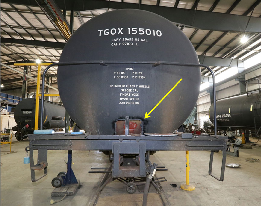
1.16.1 TGOX 155010 (91st car)
Tank car TGOX 155010, the lead car in the uncontrolled cut of cars, was manufactured by Gunderson. The A-end of the car had been leading as the cut of cars descended the pullback lead track. Based on an examination of the A-end, the following was determined:
- There was no visible impact damage on the coupler, striker face or coupler horn.
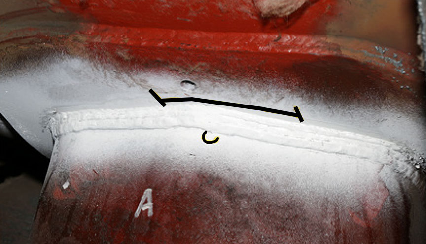
- The head brace to pad weld exhibited cracking at the toe of the top weld pass. Magnetic particle inspection (MPI) confirmed the presence of intermittent cracking about 4.5 inches long, 1 inch to the left and 3.5 inches to the right of the tank car centreline.
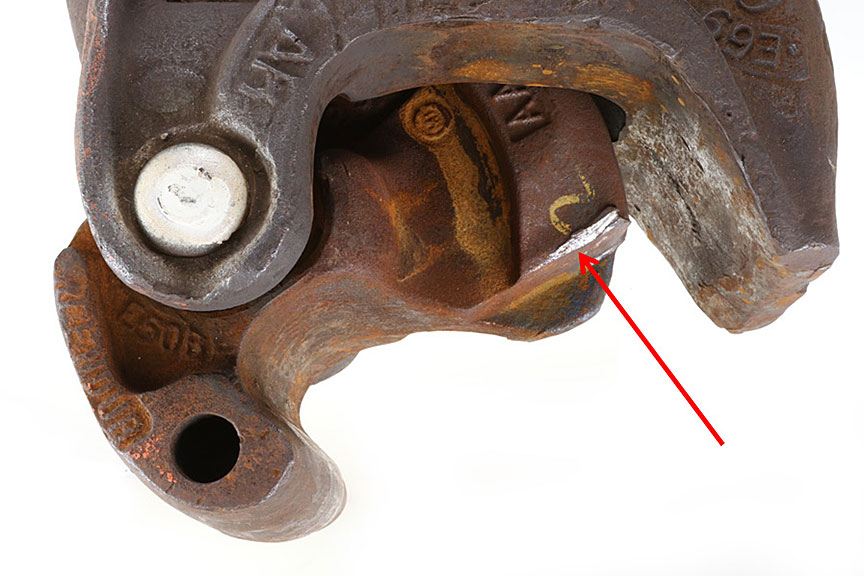
- A small 3/16-inch crack long indication was observed at the toe of the bottom pass of the brace to pad weld, at the centreline of the car (Figure 7).
- Draft pocket inspection revealed possible indications of cracking. A small MPI indication was observed in the top weld of the inboard left side draft lug. This indication was at the end of a weld pass on top of other weld passes. A second indication was observed mid-length of this. No other indications or signs of impact damage were observed.
- The underside of the car near the inboard end of the stub sill where it joins to the tank reinforcing pad displayed buckling deformation of the tank shell. To determine the amount of buckling, a 24-inch straight edge was held against the bottom of the tank reinforcing pad and parallel with the centreline of the car. Vertical perturbations in the surface were evident. The deformation was also examined from inside the car. The maximum tank buckling observed at the A-end of the car was near the inboard end of the first shell ring and measured about ½ inch vertically inward from the bottom of the car. In total, the buckled area formed an elliptical deformation that measured about 29 inches longitudinally and 34 inches circumferentially.
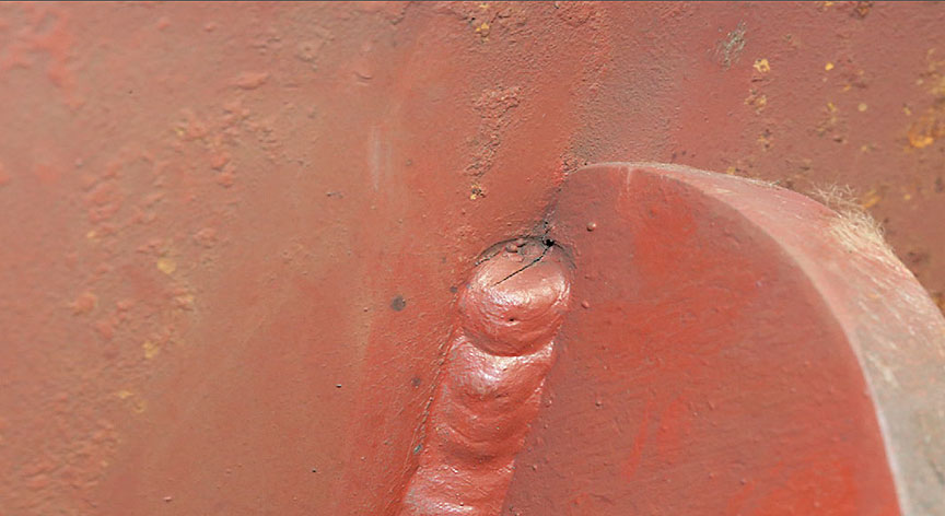
- The car body bolsters revealed cracks in the welds at the junction of the car body bolster extension and the bolster reinforcing pad. Cracks in these welds were visually apparent (Figure 8), and confirmed by MPI inspection, in the end of the weld bead on both sides of the bolster extension at all 4 locations at all 4 body bolster extensions.
- No cracks were observed at any welds to the tank shell.
Based on an examination of the B-end, the following was determined:
- Minor impact damage was observed on the top shelf of the double shelf coupler, but no impact damage was observed on the striker face or coupler horn.
- MPI of the head brace–to–pad weld revealed a small discontinuous indication about ¼ inch long located 3/16 inch to the left and 1/16 inch to the right of the tank car centreline.
- The B-end draft pocket did not exhibit any cracks or deformation as a result of the occurrence.
- The underside of the car near the inboard end of the stub sill where it joins to the tank reinforcing pad displayed buckling deformation of the tank shell. The deformation was also examined from inside the car. The maximum tank buckling observed at the A-end of the car was near the inboard end of the first shell ring and measured about 1/8 inch vertically inward from the bottom of the car, approximately 10 inches to the right of the tank car centreline.
- No cracks were observed at any welds to the tank shell.
1.16.2 TILX 255667 (90th car)
Tank car TILX 255667, which was directly behind the leading 91st car, was manufactured by Trinity. The A-end of this car was leading as the cut of cars descended the lead track. The examination revealed the following:
- Impact damage was observed on the striker face, and paint from the striker was on the coupler horn at the A-end of the car. No damage was observed on the B-end.
- External examination of the underside of the car near the inboard ends of the stub sills where they join to the tank reinforcing pad did not exhibit buckling. However, internal examination of the A-end of the car did reveal minor tank buckling in that area. The maximum tank buckling observed at the A-end of the car was near the inboard end of the first shell ring and measured 5/32 inch vertically inward from the bottom of the car. The affected area formed an elliptical deformation that measured 36 inches longitudinally and 25 inches circumferentially.
- There were no cracks observed in the head brace to pad welds, draft pockets or the welds securing the body bolster to the bolster reinforcing pads at either end of the car.
- No cracks were observed at any welds to the tank shell.
1.16.3 TILX 281395 (89th car)
Tank car TILX 281395, which was the 3rd car of the uncontrolled cut of cars, was also manufactured by Trinity. The A-end of this car was leading as the cut of cars descended the lead track. The examination determined the following:
- There was no impact damage observed on the striker faces or coupler horns on either end.
- External and internal examination of the car near the inboard ends of the stub sills where they join to the tank reinforcing pad did not exhibit any buckling.
- There were no cracks observed in the head brace to pad welds, draft pockets or in the welds between the body bolster and the bolster reinforcing pads at either end of the car. In addition, no cracks were observed at any welds to the tank shell.
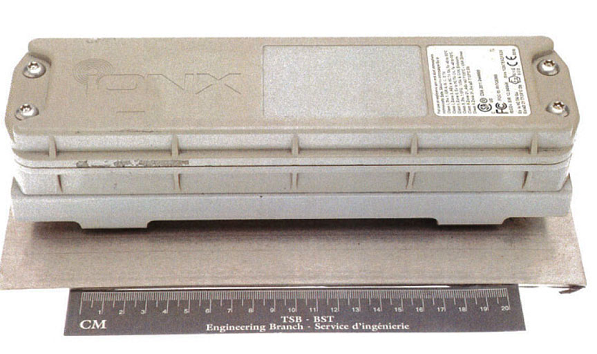
Tank car TILX 281395 was also equipped with an IONX data acquisition unit (the unit) telemetry device. The unit was installed on the top centre of the tank near the manway entrance (Figure 9). The unit was recovered and sent to the TSB Engineering Laboratory to extract any available data from the unit in support of the investigation.
1.16.4 Tank car repairs
The ½-inch buckle located at the bottom of the B-end of the TGOX 155010 tank shell was cut out and replaced. All crack indications observed on car TGOX 155010 were ground out and repair-welded. Repairs were completed in April 2016.
None of the shell damage observed was visible without removing portions of the car jacket and insulation for external examination of the shell or entering the tank for internal examination.
1.17 Emerging freight car telemetry technology
For at least 15 years, telemetry technology has been used in railway service to track the location and specific operating conditions of railway rolling stock. Initially, shippers of high-value, impact-sensitive products used this technology to monitor their products during shipping. More recently, in response to potential vandalism or security threats, and events such as the Lac-Mégantic train derailment (TSB Railway Investigation Report R13D0054), the technology has been used to monitor critical car components such as the application of hand brakes, truck performance, as well as temperature and securement of toxic inhalation hazard shipments.
It has been estimated that over 40 000 railway freight cars have been equipped with telemetry devices. These devices routinely record date, time, location, global positioning system (GPS) coordinates as well as acceleration events, including duration and peak force events in horizontal, vertical and longitudinal axes. The data are typically uplinked at regular intervals and, when an event occurs, via a cellular or a satellite network to a central database.
In 2010, rail car owner and leasing company GATX conducted a pilot project to determine to what extent telemetry devices could add value from a maintenance and commercial standpoint. The project was conducted with the 2 major telemetry equipment suppliers that had telemetry devices mounted on GATX tank cars. The study determined that there was high value for the following applications:
- Hand brake sensors to identify systemic areas when hand brakes were being left on
- Impact sensors to determine systemic areas of rough car handling and damage
However, at that time, without AAR acceptance of the technology and the associated changes that would be required to the AAR MSRP or rules, there was little that could be done to address operational issues among the handling lines or customers. In some cases, handlers who were not familiar with the technology interpreted it as a security threat.Footnote 26
Since the pilot project, battery life and monitoring capability have continued to improve as additional parameters have been added. Acceleration and force data can now be generated when the car type is calibrated and mounting location is standardized.Footnote 27
1.18 TSB laboratory examination of IONX data acquisition unit
The IONX data acquisition unit was a standalone device and had no wireless sensors associated with it. The unit is battery-operated, and battery life was estimated to be 5 to 7 years. The unit captures time, GPS latitude and longitude, along with acceleration magnitude and duration along all 3 axes. Data are recorded as location events and acceleration-triggered events. Location events capture date, time, location, latitude and longitude.
The unit was set to record a location event every 6 hours. Acceleration-triggered events capture the same data as location events plus longitudinal, lateral, and vertical acceleration magnitudes and durations. When acceleration reaches 3g along at least 1 of the 3 axes, an acceleration event is recorded. Events captured within 2 minutes of each other re-use the same location information. Although the location data are set to capture a point every 6 hours, an additional location capture is produced when an acceleration event occurs.
The unit periodically transmits all recorded data to a central server. A download of the server file was forwarded to the TSB for analysis. The file included 429 data points covering the period from 01 July 2015 to 16 October 2015.
For the date of the occurrence, the data file contained 6 entries. One of the entries had been triggered due to a longitudinal acceleration of 10.06 g, which was the peak sensed acceleration for this event. The data captured at this trigger point are shown in Table 2 along with the location events that were recorded before and after the acceleration-triggered event.
| Category | Previous data | Triggered data | Next data |
|---|---|---|---|
| Event data and UTC time | 2015-07-29 15:49:26 | 2015-07-29 17:32:35 | 2015-07-29 17:32:44 |
| Event type | Location | Accelerometer event | Location |
| Location | Vaughan, Ontario | Vaughan, Ontario | Vaughan, Ontario |
| Latitude | 43.807159 | 43.807159 | 43.807159 |
| Longitude | -79.5062656 | -79.5062656 | -79.5062656 |
| Acceleration longitudinal | - | 10.06 | - |
| Acceleration lateral | - | 2.09 | - |
| Acceleration vertical | - | 7.41 | - |
| Duration longitudinal | - | 0.05523811 | - |
| Duration lateral | - | 0.009667282 | - |
| Duration | - | 0.01991882 | - |
The acceleration-triggered event occurred about 2 hours after a location event. After the acceleration-triggered event, there is a 9-second lapse before the next location event.
Using the recorded longitudinal deceleration and duration, an estimate of the initial speed of the 89th car (TILX 281395) was performed. The calculation produced an initial speed at the time of triggering of the accelerometer event of about 19.6 km/h (12.2 mph). This value was close to the speed of the cut of cars previously estimated by the TSB at between 12.8 and 13.3 mph (about 13 mph) at the time of the collision.
1.19 Coupler and knuckle information
Coupler assemblies are located at both ends of rail cars to connect them to other cars to form a train. Upon interaction with another car, the coupler knuckle is designed to automatically transition from an open position to a closed-and-locked position. When closing, the knuckle rotates around the knuckle pin such that the face of the knuckle engages with the knuckle face of the adjoining coupler and they both lock into place when the knuckle tails retract into each coupler body. Once fully retracted, the tail of the knuckle is restrained by a locking block. The locking block is designed to drop down between the tail of the knuckle and the coupler body to prevent the knuckle from opening unintentionally.
Coupler knuckles are opened by manual operation of an uncoupling lever. When manually operated and lifted, the uncoupling lever moves the lock-lift assembly vertically, which in turn lifts the locking block and frees the tail of the knuckle. Further rotation of the uncoupling lever will force the leg of the locking block to engage the knuckle thrower, which then opens the knuckle. Undesired release of the knuckle is avoided by the anti-creep design of the lock-lift assembly, which prevents upward vertical movement of the locking block, unless the lock-lift assembly is activated by the uncoupling lever.
There are no field inspection gauges for the lock-lift assembly or the locking block. There is no finite life for these components. AAR rules prohibit the application of secondhand lock-lift assemblies. However, lock-lift assemblies can be re-applied to a car if the coupler body or knuckle is changed out.Footnote 28 Lock-lift assemblies are not allowed to be reconditioned.Footnote 29
Part II, section 15, Couplers and Drawbars, of the TC-approved Railway Freight Car Inspection and Safety Rules states (in part)Footnote 30
15.1 A railway company shall not place or continue a car in service if:
[…]
- the car has a coupler with an inoperative lock-lift or a coupler assembly that does not have anti-creep protection to prevent unintentional unlocking of the coupler lock;
- the coupler lock is missing, inoperative, bent, cracked or broken.
[…]
There is no inspection mechanism currently in place to ensure that lock-lift assemblies are in serviceable condition.
1.20 Pulling force and grade resistance
Locomotive wheel slip occurs when a locomotive tractive effort exceeds the available rail adhesion. High tractive effort is needed to pull heavy loads up ascending grades, but wheel slip will also occur when the tractive effort delivered by locomotives exceeds the rail adhesion available at the wheel/rail interface. Tractive effort is equal to the pulling force on the first car's lead coupler and knuckle. Similarly, grade resistance also equates to the pulling load for couplers and knuckles. The safe range of pulling force exerted on couplers and knuckles in particular is well known in the industry and is outlined in the AAR Train Make-up Manual.Footnote 31 Although the document was produced in 1992, the information is still used by railways today. The AAR Train Make-up Manual states (in part)
4.0 Excessive Train Forces
4.1 Steady State Forces
Steady state forces are the basis for an initial computation of acceptable train make-up. Steady state forces are those that are applied for a relatively long period of time, such as steady pull up an ascending grade or retardation under dynamic brakes. Train longitudinal forces result in lateral track loading that may be significant depending on such factors as degree of curve and length of coupled cars. These forces, when large, can create problems.
4.1.1 Train Separation
Excessively high draft forces may exceed the strength of the materials used in the draft system resulting in mechanical failure and subsequent train separation. The knuckle is designed as the weak link, a mechanical "fuse", in this system. When draft forces approach levels that might damage a car, the knuckle fails instead of the car.
Currently, two different coupler system materials are used in North America, Grade C and Grade E steel. Grade C material, the weaker of the two, is normally used in unrestricted interchange equipment. It has an accepted working limit (pulling force) of 250,000 pounds in draft with an ultimate design load limit of 300,000 pounds. When calculating general merchandise train make-up, this value is generally used to develop guidelines for train make-up and train handling.
Grade E equipment, sometimes known as "high tensile" or marked "HTE" equipment, has an accepted working limit of 350,000 pounds in draft with an ultimate design load limit of 400,000 pounds. This value may be used to develop guidelines for train makeup and train handling where it is positively known that no Grade C equipment will be entrained.
The values for working limits were selected after reviewing coupler specifications and the coupler load environment data found in the AAR MSRP.
Although Grade C components are being replaced with the more robust Grade E components, many Grade C couplers and knuckles remain in service today.
Pulling loads above accepted working limits can result in permanent knuckle deformation and can ultimately result in knuckle failure and/or a train separation. Older knuckles of the same class can also have a reduced load capacity due to wear, particularly if cracks or material defects are present.
Grade resistance and the pulling load for couplers and knuckles can be calculated.Footnote 32 It has been a generally accepted rail industry operating practice that the “safe” pulling load range should not exceed 300 000 pounds.Footnote 33
1.21 TSB laboratory examination of freight car CN 44257 draft system
The respective coupler assemblies from the locomotive and the flat car were examined (Figure 10).
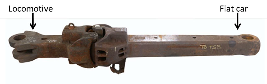
There were no defects observed in the locomotive CN 7506 coupler assembly.
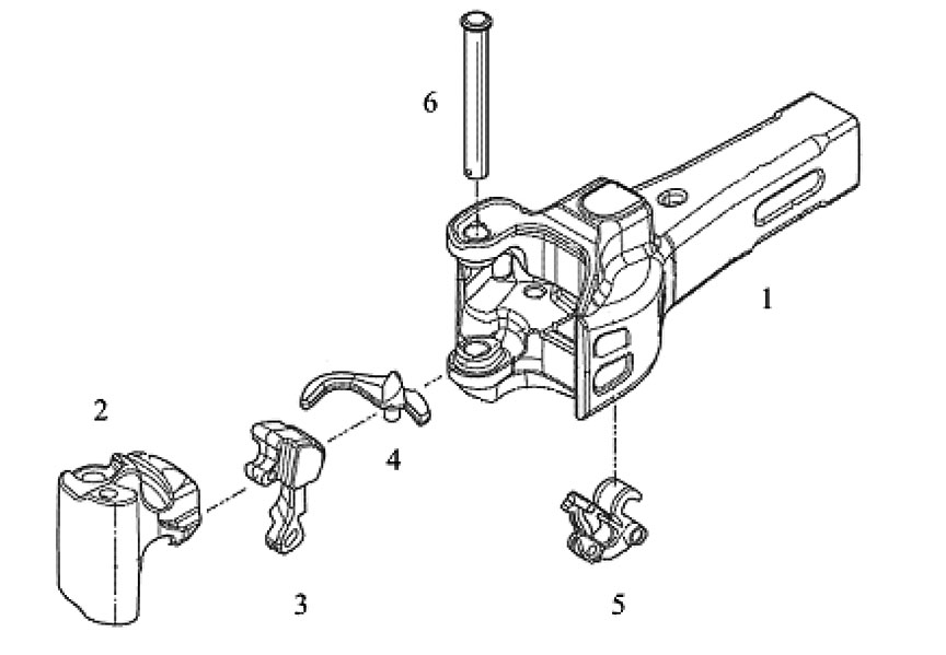
A coupler assembly consists of the coupler body, the knuckle, the knuckle locking block, the knuckle thrower, the lock-lift assembly, and the knuckle pin (Figure 11).
The coupler from flat car CN 44257 was a bottom-operated type E/F coupler that had a type E coupler head with the long shank of a type F coupler. The markings on the CN 44257 coupler assembly components are listed in Table∇3.
| Component | Marking | Meaning |
|---|---|---|
| Coupler body | E69AE | Type E, coupler body, original design, Grade E cast steel |
| CSF | Manufactured by Canadian Steel Foundries | |
| 11-81 | Date of manufacture - November 1981 | |
| Knuckle | E50BE | Type E, knuckle, revision B, Grade E cast steel |
| MT | Manufactured by McConway and Torley | |
| HI ENDUR | High endurance model | |
| 8 01 15 | Date of manufacture - 8 January 2015 | |
| Locking block | E42AE | Type E, Lock (bottom), original design, Grade E cast steel |
| Lock-lift assembly | E24B | Lock-lift assembly |
In May 2015, CN Transcona shop in Winnipeg, Manitoba, had changed out the B-end knuckle. The B-end coupler and its other components were likely original to the car, which was built in April 1982. Only the B-end knuckle was changed out as the rest of the components were not condemnable.
There were no markings stamped on the coupler horn, indicating that it had not been reconditioned. No cracking, deformation or excessive wear was present on the coupler head or body.
The coupler met the specified AAR test requirements. The knuckle and locking block met the specified hardness and chemical requirements for Grade E steel. The knuckle and locking block were inspected in accordance with the AAR dimensional guidelines. The knuckle passed the inspection and its contour fit within the coupler body was acceptable. While the overall width of the locking block passed the test, an indentation worn in the side of the locking block due to contact with the tail of the knuckle exceeded limits.
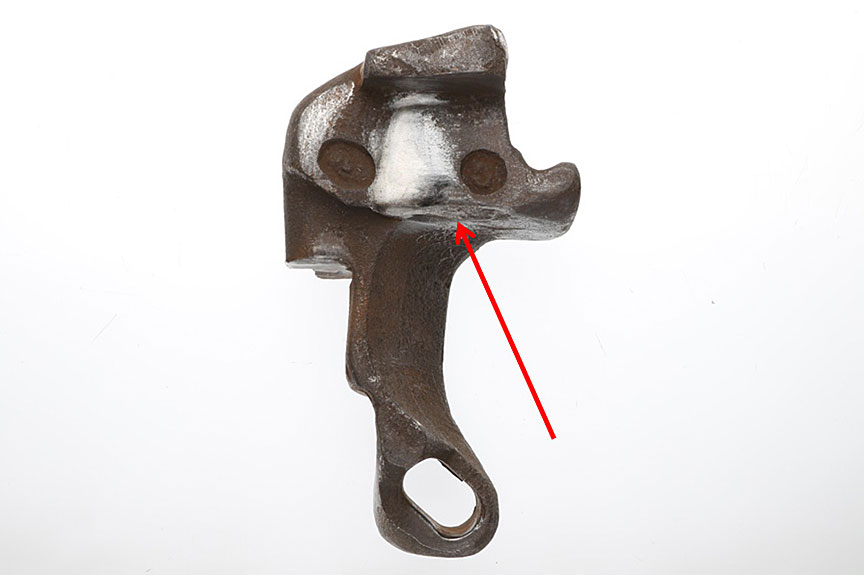
Minor deformation with a fresh (not rusted) appearance was present on the top edge of the knuckle tail (Figure 12). Deformed metal with a fresh appearance was also present on the corresponding surface of the bottom inside corner of the locking block (Figure 13).
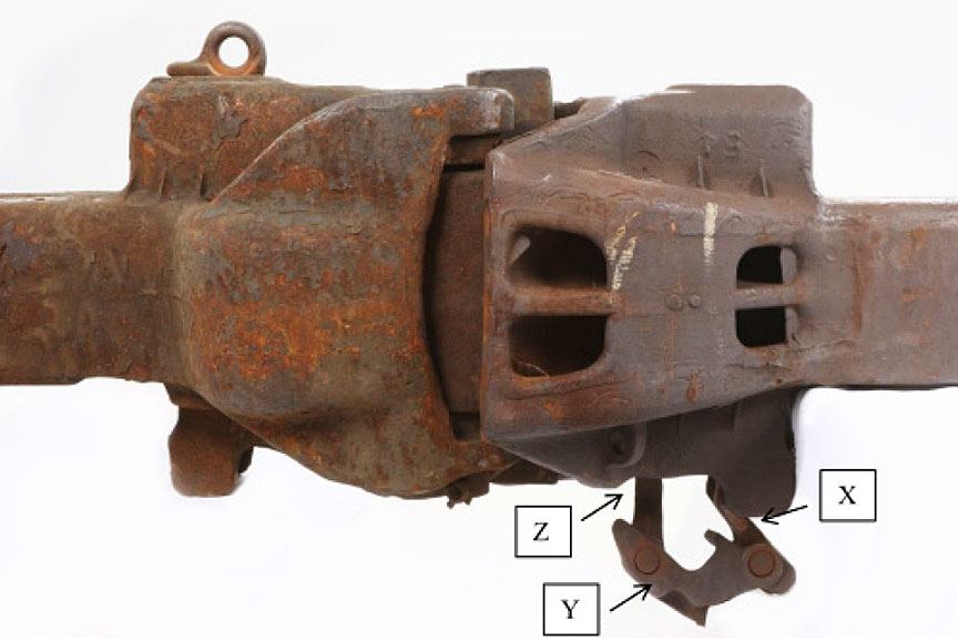
The lock-lift assembly consisted of 3 parts: toggle X, toggle Y and toggle Z. Toggle X sits on the trunnion at the bottom of the coupler body (Figure 14). Toggle Z engages with the tail of the locking block. Toggle Y, which couples to toggle X and toggle Z, provides the attachment for the uncoupling lever.
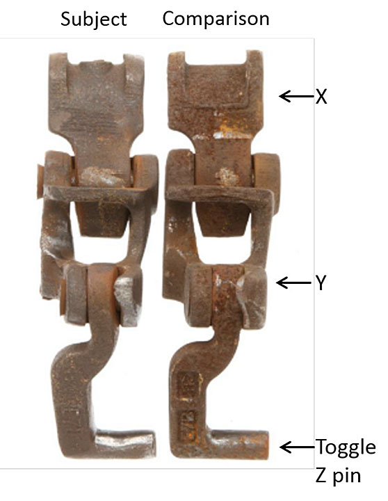
The lock-lift assembly exhibited extensive wear in the toggle joints and rivets when compared to a newer assembly (Figure 15). This extensive wear increased the lateral movement of toggle Z.
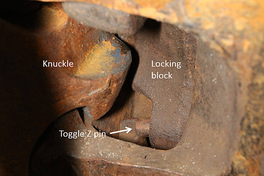
Anti-creep protection is provided to prevent unintentional uncoupling. An anti-creep test was performed on the coupler assembly in accordance with the AAR guidelines. The anti-creep protection functioned as intended. However, when closing the knuckle, the toggle Z pin of the lock-lift assembly occasionally jammed in the locking block hole, preventing the block from dropping into place (Figure 16).
When the toggle Z pin of the lock-lift assembly jammed in the locking block hole, the locking block only partially engaged with the tail of the knuckle (Figure 17 and Figure 18).
Since the uncoupling lever hangs on 1 side of toggle Y, a side load is created in the lock-lift assembly during operation. Toggle Z displayed wear on the side and middle of the end pin that is inserted in the locking block hole in the tail of the block. The observed wear on the end pin of toggle Z was consistent with its interaction with the locking block hole and misalignment due to excessive lateral movement of the lock-lift assembly.
1.22 TSB unplanned/uncontrolled movement occurrence statistics
Since 2007, there have been 392 occurrencesFootnote 34 reported to the TSB related to unplanned/uncontrolled movements among all railways in Canada (Figure 19).
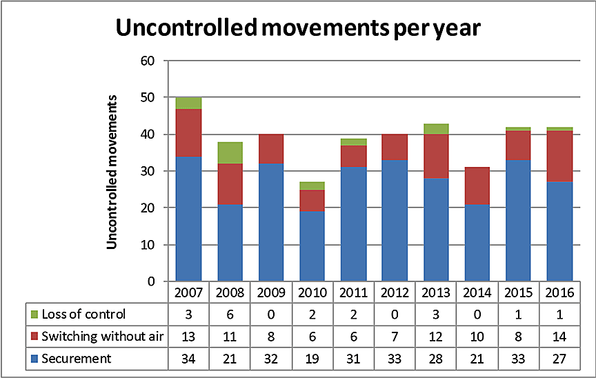
Uncontrolled movements generally fall into 1 of 3 causal categories:
- Loss of control – When a locomotive engineer or a Beltpack operator cannot control a train when using the available air brakes.
- Switching without air – When a yard movement is switching with only the use of the locomotive air brakes (i.e., no air brakes are available on the cars being switched). When an uncontrolled movement occurs, these situations can result in the cars exiting the yard and entering onto the main track.
- Securement - When a car, a cut of cars or a train is left unattended and begins to roll away uncontrolled usually due to
- no hand brake applied or insufficient number of hand brakes applied; and/or
- air bleeding off of cars left standing with an emergency air brake application and the train air brakes subsequently releasing; and/or
- a car (or cars) is equipped with faulty or ineffective hand brakes.
Of the 392 occurrences,
- insufficient securement was the primary factor in 279 (71%);
- switching without air, as was the case in this occurrence, was the primary factor in 95 (24%);
- loss of control was the primary factor in 18 (5%).
These occurrences were also categorized according to their consequences (Table 4).
| Consequence | 2007 | 2008 | 2009 | 2010 | 2011 | 2012 | 2013 | 2014 | 2015 | 2016 | Total |
|---|---|---|---|---|---|---|---|---|---|---|---|
| Derailment of 1 to 5 cars | 25 | 16 | 23 | 14 | 16 | 17 | 17 | 17 | 24 | 23 | 192 |
| Derailment of more than 5 cars | 1 | 4 | 1 | 0 | 0 | 2 | 1 | 0 | 1 | 1 | 11 |
| Collision | 28 | 15 | 22 | 13 | 22 | 18 | 17 | 12 | 18 | 21 | 186 |
| Affected the main track | 11 | 9 | 5 | 4 | 7 | 6 | 8 | 7 | 3 | 5 | 65 |
| Involving DGs | 11 | 11 | 9 | 3 | 6 | 4 | 7 | 6 | 10 | 8 | 75 |
| Injuries or fatalities | 4 | 1 | 1 | 0 | 0 | 2 | 50 | 0 | 0 | 0 | 58 |
Of the 392 occurrences,
- 186 unplanned/uncontrolled movements (47%) resulted in a collision;
- 65 unplanned/uncontrolled movements (17%) affected the main track.
Since 1994, the TSB has investigated 27 occurrences (including this occurrence) that involved runaway rolling stock (Appendix A).
1.23 Other TSB investigations involving over-speed coupling
Since 2003, the TSB has investigated 2 occurrences related to over-speed coupling during humping operations in Toronto.
R03T0026 – On 21 January 2003, at Canadian Pacific Railway Toronto Yard, a residue tank car, last containing sodium hydroxide (UN 1824), was released from the hump into classification track C–34 and struck a stationary box car at an estimated speed of 12 mph. Both cars sustained damage. There were no derailment, product release, or injuries.
The investigation determined that between November 2002 and January 2003, 4 over-speed couplings involving DG had occurred at Toronto Yard. The investigation determined that regulatory requirements regarding the coupling of rail vehicles were put into place without any means to measure coupling speeds. Records were not kept unless damage was identified during a visual inspection. The regulations only addressed DG tank cars, increasing the risk for in-service failures of other rolling stock.
R03T0047 - On 04 February 2003, DG tank car PROX 77811 was observed in CN MacMillan Yard with product leaking from the A-end of the car. Subsequent inspection identified a 20‑inch crack in the tank in the area of the stub sill. The investigation determined that the tank car had recently experienced multiple over-speed coupling events in MacMillan Yard, including 1 event during which the car coupled at a predicted speed of over 13 mph (20.9 km/h). The car was not inspected after the over-speed couplings and was allowed to proceed to destination at a nearby loading facility, where the crack in the tank was identified.
It was also determined that railways have neither a reliable means of directly measuring actual coupling speeds, nor a documented process to ensure cars that may have experienced excessive speed coupling events are identified and inspected before being allowed to continue in service. The Board issued the following safety concern:
Without the means in place to directly measure actual coupling speeds or the longitudinal force generated during coupling, the TSB remains concerned that current hump yard protocols will allow rail cars involved in over-speed couplings to continue in service.
1.24 TSB Watchlist
Safety management and oversight will remain on the TSB Watchlist until
- Companies that do have an SMS must demonstrate that it is working (i.e., that hazards are being identified and effective risk mitigation measures are being implemented).
- When companies are unable to effectively manage safety, TC must not only intervene, but do so in a manner that succeeds in changing unsafe operating practices.
The TSB Watchlist identifies the key safety issues that need to be addressed to make Canada's transportation system even safer.
Safety management and oversight is a Watchlist 2016 issue. As this occurrence demonstrates, missed opportunities to analyse events such as unplanned train separations can result in the failure to implement corrective actions to mitigate risks and improve safety.
1.25 TSB laboratory reports
The TSB completed the following laboratory reports in support of this investigation:
- LP 137/2016 - Video Analysis
- LP 153/2015 - Collision Analysis
- LP 171/2015 - Draft System Teardown and Analysis
- LP 226/2015 - Inspection of Tank Car Stub Sills
- LP 242/2015 – Non-Volatile Memory Recovery - Data Collection Unit
2.0 Analysis
No track defects contributed to the accident. The analysis will focus on the circumstances that contributed to the separation of the assignment and the resulting uncontrolled movement and collision with train A42241-29 (train 422). The analysis will also focus on the in-train forces produced during the collision, secondary defences against uncontrolled movements in MacMillan Yard, industry compliance, and regulatory enforcement of section 10.7 of the Transportation of Dangerous Goods Regulations .TDG Regulations).
2.1 The accident
The accident occurred when a cut of 91 cars weighing about 9000 tons separated from the assignment as it was being pulled northward up the east pullback track in preparation for humping operations. As was usual during hump yard pullback operations, no air was applied to any of the cars.
After separating from the assignment, the 6100-foot-long cut of cars initially came to a stop occupying about 4700 feet on the east pullback track north of switch 18 and about 1400 feet of track south of switch 18. After stopping, the cut of cars began to roll uncontrolled southward (in reverse) following the route it had just come from on track R-13. With only active air brakes on the controlling locomotives, once the assignment separated, the cut of cars, led by 24 tank cars loaded with petroleum crude oil (UN 1267), rolled uncontrolled southward for about 4500 feet on a descending grade back into track R-13 and collided with train 422 at about 13 mph.Footnote 35
Although none of the cars of the cut of cars derailed, the head-end locomotives of train 422 were shoved back about 350 feet, resulting in the derailment of 10 of the train's cars on track R-13 and 1 car on adjacent track R-11. Derailed equipment from train 422 included an empty (residue) tank car that last contained sulphuric acid (UN 1830). A second car on track R-11 and 1 car on track R-10 were damaged. Approximately 585 feet from tracks R-13, R-14 and R‑16 was damaged.
2.2 Train separation
The separation of the assignment occurred at the north end of the assignment between trailing locomotive CN 7506 and the leading B-end of the 1st car (CN 44257) behind the locomotive. The knuckles on both the locomotive and car were not broken. The knuckle on assignment locomotive CN 7506 had remained closed and locked, but the adjoining knuckle on the B-end of flat car CN 44257 had opened.
There were no defects present in the locomotive coupler assembly. However, the locking block and the lock-lift assembly of the B-end coupler on CN 44257 were extensively worn.
2.2.1 Coupler components
The overall width of the locking block was acceptable. However, an indentation worn into the side of the locking block due to contact with the tail of the knuckle exceeded limits. While the coupler's anti-creep mechanism usually functioned as intended, when closing the knuckle, the toggle Z pin of the lock-lift assembly occasionally jammed in the locking block hole and prevented the block from dropping and fully engaging in place. The worn condition of the lock-lift assembly allowed excessive lateral movement of the toggle Z pin, such that it occasionally prevented proper operation of the locking block.
Minor deformation present on the top edge of the knuckle tail and the corresponding surface of the bottom inside corner of the locking block was also consistent with the locking block having partially dropped into place and not always being fully engaged. Given the observed wear, this condition may have existed before the occurrence. The wear within the lock-lift assembly of the B-end coupler of CN 44257 allowed excessive lateral movement of the toggle Z pin such that it jammed in the locking block hole and prevented the block from completely dropping and locking into place. Therefore, the locking block was likely only partially engaged following the assignment's initial successful coupling, allowing the assignment to be pulled out of track R-13 without the knuckle opening.
With only air brakes on the locomotives, the assignment commenced movement northward. As the assignment was pulling the approximately 9000-ton cut of cars northward up the ascending grade onto the east pullback track, the pulling force on the B-end knuckle and coupler of CN 44257 had been steadily increasing. Upon reaching a peak load near the top of the east pullback track, the partially engaged edges of the locking block and knuckle yielded, allowing the locking block to rise out of position and the knuckle to open, releasing the cut of 91 cars.
2.2.2 Visual confirmation of lock-lift assembly during coupling
At Canadian National Railway Company (CN), operations personnel were instructed to look for proper alignment of the bottom-operated lock-lift assembly pivot points (toggles) when monitoring a joint to ensure the coupler locking block had dropped properly into place to secure the knuckle. The occurrence conductor was familiar with yard operations and had a 100% pass rate on efficiency tests related to coupling to equipment.
During coupling to equipment, the joint must also be stretched to ensure the integrity of the coupling. In this occurrence, the conductor made 2 attempts to couple the assignment to the cut of cars on track R-13. In both attempts, the conductor observed the coupling from a position on the ground and stretched the movement to check the joint. The first attempt to couple was unsuccessful and the assignment separated from the cut of cars when the joint was stretched. Shortly thereafter, a second coupling attempt appeared to be successful.
If a coupler locking block is only partially engaged, the lock-lift assembly would still be misaligned following a coupling, which would indicate that the locking block had not dropped. Therefore, despite an apparent successful second attempt to couple, the conductor likely did not visually confirm that the lock-lift assembly of the coupler on the B-end of CN 44257 was properly aligned and did not confirm that the locking block was fully engaged before commencing the northward movement.
When a knuckle does not lock into place as intended, it will usually swing open when the joint is stretched. However, as was the case in this occurrence, there are times when couplers with improperly seated locking blocks will remain coupled during stretching. This reinforces the importance of visually confirming the proper alignment of the lock-lift assembly when coupling to further confirm that the knuckle is properly locked. When proper alignment of the lock-lift assembly is not visually confirmed during coupling, inadequate couplings can remain undetected.
2.2.3 Lock-lift assembly
The lock-lift assembly is a critical component that ensures the knuckle locking mechanism functions as designed. However, the lock-lift assembly has no renewal requirement, except when broken. Over time, this component can wear to a point where it can jam, increasing the likelihood of a failed coupling and a train separation. In comparison, the knuckle, which is another critical component, has condemning criteria and is often changed out before wear can cause a train separation.
In May 2015, CN Transcona shop in Winnipeg, Manitoba, had changed out the B-end knuckle. The B-end coupler was manufactured in November 1981. The coupler and its other components were likely original to the car, which was built in April 1982. Only the B-end knuckle was changed out as the rest of the components were not condemnable. The coupler locking block and lock-lift assembly were not changed as there were no Association of American Railroads (AAR) wear criteria for replacement of these components. They would only be replaced when broken.
There are no inspection gauges for the lock-lift assembly. In addition, there is no date of manufacture stamped or cast on the assembly and there is no limit on service life. The 2015 Field Manual of the AAR Interchange Rules (AAR rules) prohibit the application of secondhand lock-lift assemblies, but these components may be re-applied to a car if the coupler body or knuckle is changed out, which had occurred in this case. As lock-lift assemblies cannot be reconditioned, it was likely original to the coupler assembly. The lock-lift assembly was potentially over 30 years old and worn to such an extent that the toggle Z pin jammed in the locking block hole and prevented the block from locking into place. If defined renewal criteria or finite life for lock-lift assemblies are not implemented, worn lock-lift assemblies can remain in service, increasing the risk of malfunctioning knuckles and unplanned train separations.
2.3 Defences for unplanned or uncontrolled movements in yard operations
The momentum of the separated cut of cars carried them up the grade for another 700 feet before slowing to a stop. The separated cars reversed direction and began to roll uncontrolled back down the grade. When train separation occurs within a yard that results in an unplanned or uncontrolled movement, attempts are made to bring the cars back under control if it is safe to do so. This can be done by applying hand brakes, moving locomotives to a position where they can slow the movement, or directing the cars into a track where they can be safely stopped with a minimal risk of collision or derailment. However, these approaches require that a crew be aware that a train separation has occurred and are also dependent on where the separation occurs within the movement and where the movement is located within the yard.
In this occurrence, there was no additional remote control locomotive system (RCLS) operator on the locomotives. The conductor, who was working alone, was properly positioned on the ground at the south end of the assignment near the east pullback lead track. As the separation took place at the north end of the assignment, the conductor could not have observed the separation. When the movement began to slow prematurely, it took time to diagnose why the cut of cars was slowing. By the time it was determined that the cars had separated and the yardmaster was alerted, the cut of cars had already stopped. The cars began to roll back down the grade and retrace their route back into track R-13, which precluded the safe use of yard employees or locomotives to bring the uncontrolled movement back under control.
The south end of the cut of cars had not cleared north of switch 18 and partially remained on the east pullback lead track, which was not equipped with any means to slow the cars.
At 1320:14, the assignment began moving northward out of track R-13. About 3 minutes later, after being authorized, train 422 began to pull into R-13 from the south and slowly proceeded behind the assignment for about the next 7 to 8 minutes. At more than 11 000 feet long and weighing over 10 000 tons, train 422 would not have been easily reversed out of the way. Under these conditions, a collision between the uncontrolled cut of cars, led by 24 tank cars loaded with petroleum crude oil, and train 422 was inevitable. The authorization of train 422 to follow behind the assignment on track R-13 placed train 422 in a vulnerable position once the assignment separated and the cut of 91 cars rolled uncontrolled southward back into track R-13.
The cut of 91 cars weighing about 9000 tons separated from the assignment while being pulled up the hump pullback track in preparation for humping operations. The cut of cars reversed and rolled uncontrolled retracing its route, down a descending grade, for 4500 feet before it collided with train 422 in the receiving yard. In the event of a train separation during pullback operations in MacMillan Yard, there were no secondary defences in place to protect against an uncontrolled cut of cars rolling back into the receiving yard. If secondary defences to protect against uncontrolled movements during humping pullback operations are not in place, a cut of cars that separates can roll uncontrolled on the descending grade, increasing the risk of collisions with other equipment.
2.3.1 Train dynamics simulation
MacMillan Yard is CN's main classification yard in Eastern Canada. Each day, thousands of cars are pulled up the pullback tracks in large, heavy movements that often contain dangerous goods (DG). The pullback tracks contain significant grades. Therefore, when an unplanned train separation occurs during pullback operations, the separated cut of cars can result in an uncontrolled movement. Like most classification yards, MacMillan Yard is designed with a bowl configuration to facilitate the switching of cars without the use of charged freight car air brakes. The assumption is that track grade, car rolling resistance, and yard speed restrictions will be sufficient to prevent serious consequences resulting from an unplanned separation and uncontrolled movement within the yard. However, the bowl configuration of the yard may not always be adequate.
A train dynamics simulation was conducted using the occurrence assignment information. The simulation determined that, if the route back into track R-13 had been unimpeded, the uncontrolled cut of 91 cars would have continued southward and arrived at the south end of track R-13 at a speed of about 11 mph. Similar results were obtained for an uncontrolled cut of cars weighing 6000 tons of similar make-up and the same would be true for an uncontrolled cut of cars of any tonnage. Therefore, when the route back into track R-13 is unimpeded, an uncontrolled cut of cars (of any tonnage) will continue back through the receiving yard, reaching the south end of track R-13 at about 11 mph, and proceed onto the MacMillan Yard inbound tracks but will not reach the main track.
2.3.2 Use of freight car air brakes during pullback operations
Trains arriving at MacMillan Yard enter the yard from the York Subdivision or the Halton Subdivision at the south end of the lower yard. The trains are routed up the inbound tracks on the east side of the yard to the receiving yard. Once a train arrives in the receiving yard, the cars are set out and inspected, and the air brake system is discharged to empty in preparation for switching with no air applied within the yard. To facilitate switching and pullback operations, generally only locomotives have functioning air brakes. As only the hump set locomotives operate with functioning air brakes during pullback operations in MacMillan Yard, when an unplanned train separation occurs before the movement clears north of switch 18, there are no secondary defences in place to prevent a cut of cars from rolling uncontrolled back into the receiving yard.
2.4 Collision forces
None of the cars of the cut derailed during the collision. In contrast, several of the empty rail cars in train 422 jackknifed vertically and were ejected while several other cars behind them derailed and came to rest in various positions.
The uncontrolled cut of cars had a mass of about 8972 tons. The initial point of collision was with the lead locomotive on train 422 (CN 2691). The collision duration ranged from 0.0545 to 0.0552 seconds. The TDG Regulations section 10.7 coupling threshold of 150 000 kg of weight at 12 km/h (7.5 mph) is equivalent to approximately 1024 kips impact force or 3.1 g acceleration in 0.0552 seconds. Based on these observations, the calculated impact force for the first 7 tank cars (85th to 91st) of the cut of cars had likely exceeded the coupling threshold specified in section 10.7 of the TDG Regulations.
The impact force at the initial point of collision between the leading 91st car (TGOX 155010) and the lead locomotive on train 422 ranged from 3500 kips to 3800 kips, which exceeded the tank shell design capacity and was almost 4 times the coupling threshold of 1024 kips specified in section 10.7 of the TDG Regulations. For the 3rd car of the cut of cars (TILX 281395 in 89th position), the impact force ranged from 2600 kips to 2800 kips, which was almost 3 times the regulatory coupling threshold. During the detailed examination of the 3rd car, no damage was identified that could be attributed to an over-speed coupling event.
The collision occurred on tangent track and the collision forces were applied through the draft system of the cut of cars, which mitigated some of the longitudinal forces on the tank shells and minimized lateral forces that otherwise could have caused the tank cars to jackknife, sustain significant impacts and rupture.
The first 8 cars behind the locomotives of train 422 contained 6 empty cars while the first 24 cars of the cut of cars (68th to 91st car) were tank cars loaded with petroleum crude oil. Although the tank car shells of TGOX 155010 (91st car) and TILX 255667 (90th car) did buckle, the peak compressive forces attained during the collision were not sustained long enough to produce catastrophic tank shell failure. Peak force duration on the loaded tank cars was reduced through car draft systems and the crumple zone created when empty or light cars near the head end of train 422 jackknifed and/or were ejected. Given the marshalling of train 422, it is likely that the derailment of its cars following the collision absorbed and dissipated much of the energy of the collision, which allowed the cut of cars to remain intact and upright on the track with minimal damage.
2.5 Tank car examination
Section 10.7 of the TDG Regulations applies to the coupling to equipment during humping or switching activities in a yard. It was not intended for uncontrolled movements that collide with stationary equipment. While an uncontrolled movement could potentially result in an over-speed coupling, the speed and inspection criteria specified in section 10.7 would not necessarily apply.
In this occurrence, the loaded tank cars at the south end of the cut of cars were involved in a collision that occurred at about 13 mph. While not required, stub sill and integrity inspections were conducted as outlined in section 10.7 of the TDG Regulations to determine if the cars were safe to return to service.
The AAR Manual of Standards and Recommended Practices (MSRP) out-of-roundness limit for these tank cars permitted shell deformation of up to 1.1 inches. The largest tank shell buckling, which occurred at the A-end of tank car TGOX 155010, was about ½ inch vertically. As such, the tank shell buckling for tank cars TGOX 155010 and TILX 255667 was not condemnable. However, Rule 95 of the AAR rules prohibits tank cars from being delivered in interchange when the bottom of a tank is known to be indented or buckled by ½ inch or more. Subsequently, the A-end tank shell buckling damage of tank car TGOX 155010 was repaired. Although none of the tank shell buckling observed in tank cars TGOX 155010 and TILX 255667 was condemnable based on the out-of-roundness limit specified in AAR MSRP, the ½-inch buckle at the A-end of TGOX 155010 required repairs to be in compliance with Rule 95 of the AAR rules.
The shell damage on TGOX 155010 and some of the cracks observed would not have been visible without removing portions of the car jacket and insulation for external examination or entering the tank for internal examination. Visual examination by railway mechanical personnel following a suspected over-speed coupling is prudent and may detect some damage. However, if tank car examination following a suspected over-speed coupling is limited to a cursory visual examination by railway personnel, shell damage or cracks in welds that are concealed by a tank car jacket and insulation might not be detected and repaired, increasing the risk of tank car failure.
2.6 Section 10.7 of the Transportation of Dangerous Goods Regulations
In 1997, the National Research Council of Canada (NRC) conducted tests to identify the maximum speed at which DG tank cars could be coupled without exceeding 1 000 000 pound-force, which corresponded to the AAR minimum longitudinal force specification for tank cars. In 2002, based on the test results, section 10.7 of the TDG Regulations was implemented.
The coupling speed and impact force criteria specified in section 10.7 were meant to ensure that when tank cars handling regulated commodities are involved in a coupling that exceeds the coupling threshold, the tank cars are immediately visually inspected by railway personnel to determine if the car is safe to travel. The regulations also require the railway to inform the car owner of the over-speed coupling to ensure that the cars receive a structural integrity inspection, a stub sill inspection, and any necessary repairs before returning to DG service.
2.6.1 Canadian National Railway Company compliance
For humping operations, CN uses its hump process control system to control car speed and to estimate the speed at which cars coupled. In 2002, CN issued instructions that required the hump supervisor to notify the on-duty transportation officer of any DG tank car involved in an over-speed coupling due to humping or flat switching. The transportation officer was then required to report the incident to the mechanical department for follow-up inspection and reporting. Despite these instructions, CN had no formal process to document over-speed couplings involving DG tank cars in MacMillan Yard before February 2015.
In February 2015, CN implemented a formal protocol for inspecting and documenting suspected over-speed couplings that occurred during humping operations in MacMillan Yard. However, no similar process was implemented to document over-speed couplings that occurred during flat switching. Between February 2015 and December 2015, there were 279 over-speed couplings that involved a total of 448 DG tank cars where the estimated coupling speed was 12 km/h (7.5 mph) or greater. Despite identifying 448 DG tank cars that required action as outlined in section 10.7 of the TDG Regulations, CN notified the tank car owners and sent the tank cars for stub sill inspections in less than 3% of the cases (13 of 448).
2.6.2 Regulatory oversight
A TSB investigation into a 2003 over-speed collision in MacMillan Yard determined that Transport Canada (TC) Transportation of Dangerous Goods (TDG) inspectors had not been instructed on how to measure the railway's compliance to coupling speed regulations. The TDG inspectors were also unsure how railways were complying with section 10.7 of the TDG Regulations. They had assumed that railways performed the required follow-up when over-speed couplings occurred. Despite these assumptions, TC TDG Directorate had no records of any monitoring or follow-up enforcement activities relating to section 10.7 of the TDG Regulations.
The TDG Directorate had ruled out the use of a radar gun to measure actual coupling speeds in a busy classification yard as this approach was considered unsafe for the TDG inspector performing the activity. As section 10.7 of the TDG Regulations is based on actual coupling speed, speed calculated using the distance-to-coupling (DTC) system is not considered enforceable, particularly as neither the regulator nor the railways have a process or system in place to measure actual coupling speed during hump operations. With a reliance on actual speed measurements and no means for railways or the regulator to measure coupling speeds, broad industry application of section 10.7 of the TDG Regulations has not occurred.
2.6.3 Risk associated with non-compliance and lack of enforcement
Many tank cars had remained in service following an estimated over-speed coupling without being inspected in accordance with section 10.7 of the TDG Regulations. This situation has been known to both the rail industry and the regulator since at least 2004 when the TSB issued a safety concern indicating that, without the means in place to directly measure actual coupling speeds or the longitudinal force generated during coupling, hump yard protocols would allow tank cars involved in over-speed couplings to continue in service.
While many of the DG tank cars involved in over-speed couplings are visually inspected by railway personnel, damage in critical locations is sometimes concealed, and the cars are not necessarily forwarded to a tank car facility for a stub sill inspection. When the DG tank cars involved are jacketed and insulated, damage and cracks in critical locations would not be visible without removing portions of the car jacket and insulation for external examination or entering the tank for internal examination. If section 10.7 of the TDG Regulationsis neither complied with nor enforced, a jacketed and insulated DG tank car that sustains damage during an over-speed coupling may remain in service, increasing the risk of an in-service DG tank car failure.
2.7 Use of on-board telemetry
In 2016, CN implemented a pilot project to determine if coupling speeds could be accurately captured within hump yards. Using the DTC speeds estimated by the hump system, CN identified 100 DG tank cars that had a potential coupling speed of greater than (>) 8 mph. These cars were inspected by CN mechanical personnel and then sent to a tank car shop for a detailed inspection as required by section 10.7 of the TDG Regulations. However, none of the 100 cars exhibited any damage to the stub sill, head brace or shell that could be associated with an over-speed coupling. CN determined that coupling speeds could not be accurately captured within hump yards using computer-based predicted coupling speeds.
For at least 15 years, telemetry technology has been used in railway service to track the location and specific operating conditions of some railway rolling stock. The technology has evolved over time as battery life improved and monitoring capabilities were expanded as additional parameters were added. Reasonably reliable acceleration and force data can now be generated when car type is calibrated and mounting location standardized. Recorded tank car impact data can be mapped against time, location, and car repair records.
There are multiple suppliers of this technology, and it has been estimated that over 40 000 railway freight cars have been equipped with telemetry devices. The devices routinely record date, time, location, global positioning system (GPS) coordinates as well as acceleration events, which include duration and peak force events in horizontal, vertical and longitudinal axes. The data are typically uplinked at regular intervals and, when an event occurs, via a cellular or a satellite network to a central server.
In this occurrence, an IONX data acquisition unit was recovered from the 3rd runaway tank car from the point of collision (TILX 281395). Data from the unit provided a reliable and useful means to calculate speed at the time of impact and the resulting impact force. The use of on-board telemetry technology presents opportunities for the industry to better understand the force environment in which tank cars operate, to identify high-risk areas of operations, and to provide a more reliable method to monitor speed and impact force during over-speed coupling events or accidents.
2.8 Safety management system
Safety management systems (SMS) were progressively introduced in the Canadian transportation industry because this approach to regulatory oversight, when combined with inspections and enforcement, is considered to be effective in reducing accident rates. A railway company should, on a continual basis, conduct analyses of its railway operations to ensure regulatory compliance and identify safety concerns, such as unplanned and uncontrolled train movements, by analyzing trends, emerging trends or repetitive unsafe situations. A robust SMS should capture, document and analyze such events with a view to expeditiously putting measures in place to minimize risks in the future.
CN had developed and implemented a detailed SMS that had been integrated into much of its operations. The SMS described company initiatives that correlated to the requirements of the Railway Safety Management System Regulations, 2015.(SMS Regulations). The SMS included a process for ensuring compliance with regulations, rules and other instruments and a process for identifying safety concerns. However, as demonstrated in this occurrence, there were gaps within CN's SMS, including the following:
- CN did not fully comply with section 10.7 of the TDG Regulations from 2002 until at least 2016.
- Despite having instructions for handling suspected over-speed couplings involving DG tank cars, CN had no reliable records of over-speed couplings involving DG tank cars in MacMillan Yard before February 2015. Without reliable data, the frequency at which over-speed couplings involving DG tank cars occurred could not be determined and no analysis could be conducted to determine if operational risks associated with humping or switching DG tank cars were emerging, improving or deteriorating.
- CN required all unplanned train separations that occurred on the main track to be documented. However, there was no requirement to report unplanned train separations that occurred in a yard, unless they resulted in a more serious event such as a collision, derailment, or employee injury. Without accurate records or trend analysis of unplanned train separations in a yard, an emerging unsafe operational issue might not be identified before an adverse consequence occurs.
If a company's SMS does not have adequate processes in place to document regulatory compliance with section 10.7 of the TDG Regulations, or to record all unplanned train separations that result in an uncontrolled movement within a yard, there are missed opportunities to analyze the events and implement corrective actions to mitigate risks and improve safety.
2.9 Evacuation of personnel
When the conductor became aware that a train separation had likely occurred, the yardmaster was advised. At 1327:10, the cut of 91 cars slowed to a stop after which the yardmaster used a yard video camera to confirm that the cut of cars had begun to roll uncontrolled southward. Over the next 4 minutes, the yardmaster informed the crew of train 422 on 3 occasions that a cut of 91 cars was rolling uncontrolled toward them and that tank cars transporting flammable liquids were on the leading end. A warning was also issued to mechanical personnel who were working on nearby tracks. Once it became evident that a collision was inevitable, the yardmaster took action in a timely manner and ensured that the crew of train 422 and mechanical personnel working on nearby tracks had sufficient time to clear the area and move to a safe location.
The crew of train 422 initially left the area and then moved back to within about 20 feet of the lead locomotive as the cut of cars approached. As the south end of the cut of cars collided head on with train 422, the crew of train 422 quickly evacuated the area to avoid injury. Despite being warned of the impending collision and evacuating the area, the crew members of train 422 moved back toward the lead locomotive and were in a vulnerable position when the collision occurred.
2.10 Unplanned/uncontrolled movement statistics
Between 2007 and 2016, there were 392 unplanned/uncontrolled movements in Canada. About 24% (95/392) of all unplanned/uncontrolled movements in Canada were related to switching without air, as in this occurrence. Of the 392 occurrences, 47% (186/392) resulted in a collision while 17% (65/392) affected the main track.
Since 1994, the TSB has investigated 27 occurrences (including this occurrence) that involved runaway rolling stock (Appendix A), a number of which resulted in significant adverse consequences including fatalities. Although the number of occurrences involving runaway rolling stock dipped to 31 in 2014, the number has since reverted to 42 for each of 2015 and 2016. The 5-year average (39.6) is about the same as the 10-year average (39.2). The number of occurrences involving runaway rolling stock has not improved over the past 10 years.
3.0 Findings
3.1 Findings as to causes and contributing factors
- The accident occurred when a cut of 91 cars weighing about 9000 tons separated from the assignment as it was being pulled northward up the east pullback track in preparation for humping operations.
- With only active air brakes on the controlling locomotives, once the assignment separated, the cut of cars, led by 24 tank cars loaded with petroleum crude oil (UN 1267), rolled uncontrolled southward for about 4500 feet on a descending grade back into track R-13 and collided with train 422 at about 13 mph.
- The wear within the lock-lift assembly of the B-end coupler for CN 44257 allowed excessive lateral movement of the toggle Z pin such that it jammed in the locking block hole and prevented the block from completely dropping and locking into place.
- The locking block was likely only partially engaged following the assignment's initial successful coupling, allowing the assignment to be pulled out of track R-13 without the knuckle opening.
- Upon reaching a peak load near the top of the east pullback track, the partially engaged edges of the locking block and knuckle yielded, allowing the locking block to rise out of position and the knuckle to open, releasing the cut of 91 cars.
- Despite an apparent successful second attempt to couple, the conductor likely did not visually confirm that the lock-lift assembly of the coupler on the B-end of CN 44257 was properly aligned and did not confirm that the locking block was fully engaged before commencing the northward movement.
- By the time it was determined that the cars had separated and the yardmaster was alerted, the cut of cars had already stopped. The cars began to roll back down the grade and retrace their route back into track R-13, which precluded the safe use of yard employees or locomotives to bring the uncontrolled movement back under control.
- The south end of the cut of cars had not cleared north of switch 18 and partially remained on the east pullback lead track, which was not equipped with any means to slow the cars.
- The authorization of train 422 to follow behind the assignment on track R-13 placed train 422 in a vulnerable position once the assignment separated and the cut of 91 cars rolled uncontrolled southward back into track R-13.
- Given the marshalling of train 422, it is likely that the derailment of its cars following the collision absorbed and dissipated much of the energy of the collision, which allowed the cut of cars to remain intact and upright on the track with minimal damage.
3.2 Findings as to risk
- If defined renewal criteria or finite life for lock-lift assemblies are not implemented, worn lock-lift assemblies can remain in service, increasing the risk of malfunctioning knuckles and unplanned train separations.
- If secondary defences to protect against uncontrolled movements during humping pullback operations are not in place, a cut of cars that separates can roll uncontrolled on the descending grade, increasing the risk of collisions with other equipment.
- If tank car examination following a suspected over-speed coupling is limited to a cursory visual examination by railway personnel, shell damage or cracks in welds that are concealed by a tank car jacket and insulation may not be detected and repaired, increasing the risk of tank car failure.
- If section 10.7 of the Transportation of Dangerous Goods Regulations.is neither complied with nor enforced, a jacketed and insulated dangerous goods (DG) tank car that sustains damage during an over-speed coupling may remain in service, increasing the risk of an in-service DG tank car failure.
- If a company's safety management system does not have adequate processes in place to document regulatory compliance with section 10.7 of the Transportation of Dangerous Goods Regulations, or to record all unplanned train separations that result in an uncontrolled movement within a yard, there are missed opportunities to analyze the events and implement corrective actions to mitigate risks and improve safety.
3.3 Other findings
- When proper alignment of the lock-lift assembly is not visually confirmed during coupling, inadequate couplings can remain undetected.
- When the route back into track R-13 is unimpeded, an uncontrolled cut of cars (of any tonnage) will continue back through the receiving yard, reaching the south end of track R-13 at about 11 mph, and proceed onto the MacMillan Yard inbound tracks but will not reach the main track.
- As only the hump set locomotives operate with functioning air brakes during pullback operations in MacMillan Yard, when an unplanned train separation occurs before the movement clears north of switch 18, there are no secondary defences in place to prevent a cut of cars from rolling uncontrolled back into the receiving yard.
- The calculated impact force for the first 7 tank cars (85th to 91st) of the cut of cars had likely exceeded the coupling threshold specified in section 10.7 of the Transportation of Dangerous Goods Regulations.
- Although none of the tank shell buckling observed in tank cars TGOX 155010 and TILX 255667 was condemnable based on the out-of-roundness limit specified in the Association of American Railroads (AAR) Manual of Standards and Recommended Practices, the ½-inch buckle at the A-end of TGOX 155010 required repairs to be in compliance with Rule 95 of the 2015 Field Manual of the AAR Interchange Rules.
- With a reliance on actual speed measurements and no means for railways or the regulator to measure coupling speeds, broad industry application of section 10.7 of the Transportation of Dangerous Goods Regulations has not occurred.
- The use of on-board telemetry technology presents opportunities for the industry to better understand the force environment in which tank cars operate, to identify high-risk areas of operations, and to provide a more reliable method to monitor speed and impact force during over-speed coupling events or accidents.
- Once it became evident that a collision was inevitable, the yardmaster took action in a timely manner and ensured that the crew of train 422 and mechanical personnel working on nearby tracks had sufficient time to clear the area and move to a safe location.
- Despite being warned of the impending collision and evacuating the area, the crew members of train 422 moved back toward the lead locomotive and were in a vulnerable position when the collision occurred.
- The number of occurrences involving runaway rolling stock has not improved over that past 10 years.
4.0 Safety action
4.1 Safety action taken
4.1.1 Canadian National Railway Company
On 31 July 2015, Canadian National Railway Company (CN) issued System Notice No. 909 entitled Ensuring the lock block is properly secured in couplers..Footnote 36 The notice states
In 2014, CN had over 100 mainline cases where a knuckle opened up causing a train separation. This could happen when a lock block or "pin" has not properly seated.
A secure joint with a seated pin will look like Figure 1 where both of the pivot points are aligned parallel to the ground. A pin that is not secured looks like Figure 2.
- When monitoring a joint look for this pattern to ensure the cars are securely coupled.
- When performing a roll-by strive to ensure the lock-lift is in position (Fig 1).
- Alert the crew when a pin is not secured to come to a controlled stop and then work the joint until it is secured.
- When a coupler is not performing properly, ask mechanical staff for help to remedy the problem.
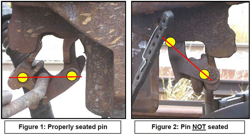
4.1.2 Transport Canada
Transport Canada (TC) conducted a general compliance inspection at MacMillan Yard on 05 August 2015, at which time it detected a non-compliance related to a damaged placard on the A-end of one rail car. The requirement of section 10.7 of the Transportation of Dangerous Goods Regulations.(TDG Regulations) was identified to CN.
On 12 May 2016, TC conducted a site inspection at CN's MacMillan Yard to verify compliance against data for all hard coupling events and records of notifications to the owners of dangerous goods tank cars at this location for the previous year. During the inspection, TC inspectors noted that tank car owners were not being notified in writing, contrary to paragraph 10.7(3)(b) of the TDG Regulations. TC took regulatory action and issued a Notice of Infraction to CN. CN responded with actions taken to remedy the non-compliance, and TC continues to work with CN to provide oversight, including being copied whenever CN notifies tank owners in writing in accordance with the requirements of the TDG Regulations.
The Transportation of Dangerous Goods (TDG) Directorate is developing a research project to determine coupling forces, car accelerations, and stub sill stresses and forces on in-service tank cars. This will involve custom and commercially available on-board telemetry. To this end, the TDG Directorate and the National Research Council of Canada (NRC) are developing a Statement of Work for a Commercial Service Tank Car Monitoring Project (TCM), which should provide a better understanding of the operating environment that tank cars and their commodities experience while in transit. The TCM project will also serve as a pilot study to assess the feasibility and the benefit of potential large-scale deployment of sensor telemetry technologies to tank car fleets.
The TCM project will consist of 2 phases of deployment of instrumentation, over 2 fiscal years, on selected commercial tank cars:
- For the 1st deployment, 90 cars will be instrumented for 6 to 12 months with sensors that will predominantly serve to identify track locations where significant increases of car body accelerations from established normal conditions occur due to changes in track conditions, train operations, and weather conditions.
- For the 2nd deployment, 10 cars will be instrumented for 6 months, to monitor more detailed conditions of tank car/track performance, such as rough rides, train action, loading conditions, dangerous goods leakage, air brake effectiveness, and vapour pressure.
NRC will conduct the testing for the TCM project. The TDG Directorate will evaluate the findings of the TCM project, which would inform any further regulatory decisions.
This report concludes the Transportation Safety Board of Canada's investigation into this occurrence. the Board authorized the release of this report on . It was officially released on .
Correction
After the publication of this report, the TSB obtained new information concerning track grade and the tractive effort and draft forces of the occurrence locomotives and booster units, which were incorrect in the original report.
Consequently, in the description of the track profile in section 1.4, the “crest of the hump” has been replaced by switch 18; the grade from the top of the east hump pullback track to switch 18 has been changed from 0.6% to 0.5%; it has been made clear that the east pullback lead track south of switch 18 descends for 800 feet at a grade of an average, not maximum, of 2.5%, after which it transitions to a shallow descending grade. A note has been added to Figure 5 (track profile) indicating that the figure is not to scale.
The calculations in the last two paragraphs of section 1.20 have been removed, and the statement, in the final paragraph, that “CN’s operating procedures for MacMillan Yard do not place any operating limits on train tonnage to be handled during pullback operations in preparation for humping” was deleted.
Because of the incorrect calculations, the original section 2.5 “In-train draft forces during pullback operations” has been removed, along with the related finding as to cause and contributing factors 11: “In-train draft forces during pullback operations in MacMillan Yard exceeded the safe operating parameters as outlined in the Association of American Railroads Train Make-up Manual” and finding as to risk 3: “If in-train draft forces are not specifically considered during pullback operations in preparation for humping, excessive pulling forces could lead to knuckle failure and train separation, increasing the risk of unplanned/uncontrolled movements”.
This correction was approved by the Board on ; the corrected version of the report was released on .
Appendices
Appendix A – TSB investigations into uncontrolled movements
| No. | Occurrence number | Date | Description | Location |
|---|---|---|---|---|
| 1. | R16W0059 | 2016-03-01 | Uncontrolled movement of railway equipment, Cando Rail Services, 2200 Co-op Refinery Complex assignment, Mile 91.10, Quappelle Subdivision. | Regina, Saskatchewan |
| 2. | R15D0103 | 2015-10-29 | Runaway and derailment of cars on non-main track, Canadian Pacific Railway, Stored cut of cars, Mile 2.24, Outremont Spur. | Montréal, Quebec |
| 3. | R13D0054 | 2013-07-06 | Runaway and main-track derailment, Montreal, Maine & Atlantic Railway, Freight train MMA-002, Mile 0.23, Sherbrooke Subdivision. | Lac-Mégantic, Quebec |
| 4. | R12E0004 | 2012-01-18 | Main-track collision, Canadian National Railway, Runaway rolling stock and train A45951-16, Mile 44.5, Grande Cache Subdivision. | Hanlon, Alberta |
| 5. | R11Q0056 | 2011-12-11 | Runaway train, Quebec North Shore and Labrador Railway, Freight train LIM-55, Mile 67.20, Wacouna Subdivision. | Dorée, Quebec |
| 6. | R09D0053 | 2009-09-09 | Non–main-track collision, VIA Rail Canada Inc., Locomotive 6425, Montréal Maintenance Centre. | Montréal, Quebec |
| 7. | R09T0057 | 2009-02-11 | Runaway and non-main-track train derailment, Southern Ontario Railway, 0900 Hagersville Switcher, Mile 0.10 and Mile 1.9 of the Hydro Spur. | Nanticoke, Ontario |
| 8. | R08V0270 | 2008-12-29 | Non-main-track train runaway and collision, Kettle Falls International Railway, Waneta Turn Assignment, Mile 141.20, Kettle Falls Subdivision. | Waneta, British Columbia |
| 9. | R07H0015 |
2007-07-04 | Runaway rolling stock, Canadian Pacific Railway, Runaway cut of cars, Mile 119.5, Winchester Subdivision. | Smiths Falls, Ontario |
| 10. | R07V0109 | 2007-04-23 | Non-main-track train derailment, Kootenay Valley Railway, 0700 Trail Yard Assignment, Mile 19.0, Rossland Subdivision. | Trail, British Columbia |
| 11. | R06V0183 |
2006-09-03 | Runaway and derailment, White Pass and Yukon Railway, Work train 114, Mile 36.5, Canadian Subdivision. | Log Cabin, British Columbia |
| 12. | R06V0136 | 2006-06-29 | Runaway and derailment, Canadian National Railway, Freight train L-567-51-29, Mile 184.8, Lillooet Subdivision. | Near Lillooet, British Columbia |
| 13. | R05H0011 | 2005-05-02 | Runaway and main-track train collision, Ottawa Central Railway, Freight train 441, Mile 34.69, Alexandria Subdivision. | Maxville, Ontario |
| 14. | R04V0100 | 2004-07-08 | Uncontrolled movement of railway rolling stock, Canadian National Railway, Train M-359-51-07, Mile 57.7, Fraser Subdivision. | Bend, British Columbia |
| 15. | R03T0026 | 2003-01-21 | Yard collision, Canadian Pacific Railway, Car No. HOKX 111044, Mile 197.0, Belleville Subdivision, Toronto Yard. | Agincourt, Ontario |
| 16. | R03T0047 | 2003-01-22 | Yard collision, Canadian National Railway, Tank Car PROX 77811, Mile 25.0, York Subdivision. | Toronto, Ontario |
| 17. | R99D0159 | 1999-08-27 | Runaway cars, Canadian National Railway, Mile 69.4, Kingston Subdivision, Wesco Spur. | Cornwall, Ontario |
| 18. | R98M0029 | 1998-09-24 | Main-track runaway, collision and derailment, Matapédia Railway, Canadian National Railway train A402-21-24, Mile 105.4, Mont-Joli Subdivision. | Mont-Joli, Quebec |
| 19. | R98M0020 | 1998-07-31 | Main-track runaway and collision, VIA Rail Canada Inc. passenger train 14 and an uncontrolled five-pak movement, Mile 105.7, Matapédia Railway Mont-Joli Subdivision. | Mont-Joli, Quebec |
| 20. | R97C0147 | 1997-12-02 | Runaway and derailment, Canadian Pacific Railway, Train 353-946, Laggan Subdivision. | Field, British Columbia |
| 21. | R96C0172 | 1996-08-12 | Main-track collision, Canadian National Railway, Train 117 and an uncontrolled movement of 20 cars, Mile 122.9, Edson Subdivision. | Near Edson, Alberta |
| 22. | R96C0209 | 1996-10-09 | Runaway cars, Canadian Pacific Railway CP 0700 Yard Assignment, Mile 166.2, Willingdon Subdivision, Clover Bar Exchange Track. | Edmonton, Alberta |
| 23. | R96T0137 | 1996-04-24 | Runaway of five tank cars, Canadian National Railway, Mile 0.0, Hagersville Subdivision. | Nanticoke, Ontario |
| 24. | R96C0086 | 1996-04-13 | Runaway train, Canadian Pacific Railway, Freight train 607-042, Mile 133.0, Laggan Subdivision. | Field, British Columbia |
| 25. | R95M0072 | 1995-12-14 | Runaway cars, Canadian National Railway, Train 130-13, Mile 0.0, Pelletier Subdivision. | Edmundston, New Brunswick |
| 26. | R94V0006 | 1994-01-18 | Runaway train, Canadian National Railway, Mile 175, Grande Cache Subdivision. | Latornell, Alberta |