Main-track train derailment
Canadian National Railway Company
Freight train C76751-17
Mile 49.07, Bulkley Subdivision
New Hazelton, British Columbia
The Transportation Safety Board of Canada (TSB) investigated this occurrence for the purpose of advancing transportation safety. It is not the function of the Board to assign fault or determine civil or criminal liability. This report is not created for use in the context of legal, disciplinary or other proceedings. See Ownership and use of content. Masculine pronouns and position titles may be used to signify all genders to comply with the Canadian Transportation Accident Investigation and Safety Board Act (S.C. 1989, c. 3).
Summary
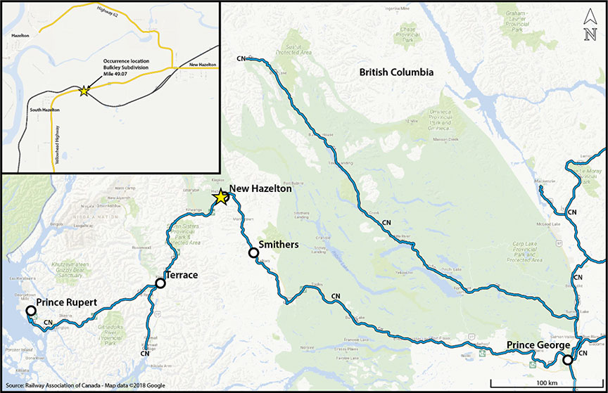
On 19 January 2018, at about 0718 Pacific Standard Time, Canadian National Railway Company freight train C76751-17, proceeding westward at 29 mph, experienced a train-initiated emergency brake application at Mile 49.07 of the Bulkley Subdivision near New Hazelton, British Columbia. A subsequent inspection determined that 27 gondola cars loaded with thermal coal had derailed, with some coal spilled into the nearby waterway. There were no injuries and no dangerous goods were involved.
Le présent rapport est également disponible en français.
1.0 Factual information
1.1 The occurrence
On 19 January 2018, at about 0525,Footnote 1 Canadian National Railway Company (CN) freight train C76751-17 departed westward from Smithers, British Columbia (Mile 0.0 of the CN Bulkley Subdivision), to Prince Rupert, British Columbia (Mile 147.4 of the CN Skeena Subdivision) (Figure 1). The distributed power train consisted of 3 locomotives and 199 gondola cars loaded with coal. The train was configured with 2 locomotives at the head end followed by 102 loaded gondola cars, 1 mid-train locomotive, and 97 loaded gondola cars. The train weighed 28 069 tons and was 10 785 feet long.
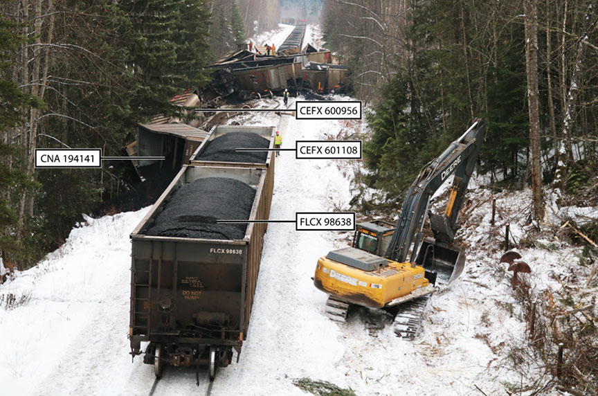
At about 0718, while proceeding at 29 mph through New Hazelton, British Columbia, on the Bulkley Subdivision, the train experienced a train-initiated emergency brake application. The crew made the required emergency radio call. When the train came to a stop, the crew inspected the train and determined that 27 cars had derailed (Figure 2).
The crew had not observed any track anomalies or experienced any operating anomalies before the emergency brake application.
At the time of the occurrence, the skies were clear with light fog, and the temperature was −2 °C.
1.2 Site examination
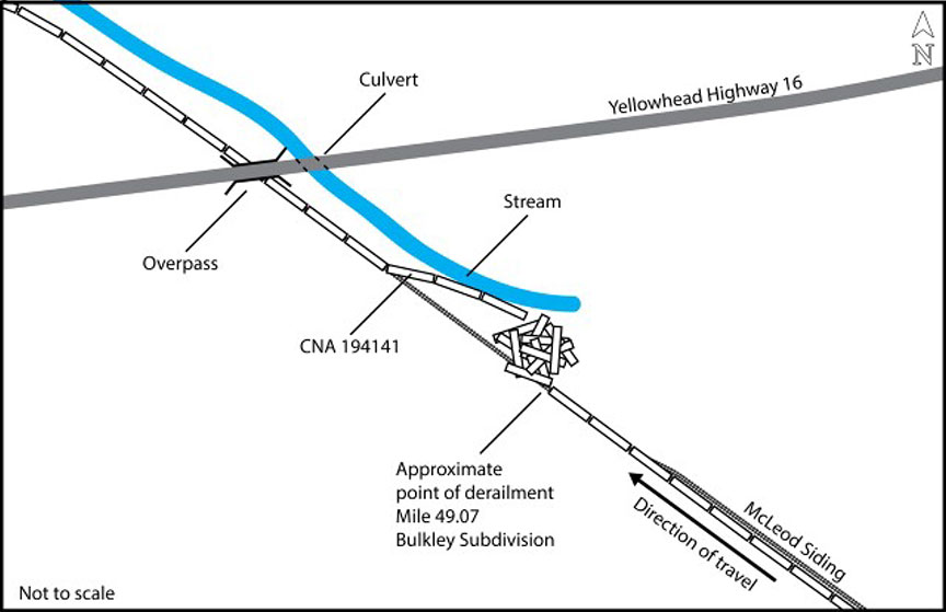
The 50th to the 76th cars derailed. The derailment spanned over 400 feet of track, resulting in localized track damage, including damage to a switch and a switch heater at Mile 48.6. Of the 27 derailed cars, the 2 west-end cars had remained upright and the following 3 cars had rolled over onto their sides and slid down the right-of-way toward Mission Creek, a nearby waterway. The remaining 22 cars had come to rest in a pile at various angles and orientations (Figure 3).
The 52nd car, CNA 194141, sustained a broken axle. The approximate point of derailment was determined to be at Mile 49.07.
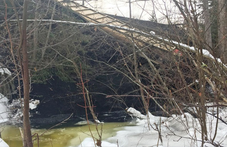
The derailment resulted in the release of approximately 2900 tons of thermal coalFootnote 2 from 24 of the derailed gondola cars. Most of the coal remained on the railway right-of-way. The estimated total volume of coal recovered was 2800 tons or 97% of the coal spilled. A small amount of coal was spilled into Mission Creek (Figure 4).
1.3 Subdivision and track information
The Bulkley Subdivision is predominantly single main track. Train movements are controlled by the centralized traffic control system, as authorized by the Canadian Rail Operating Rules, and are supervised by a rail traffic controller located in Edmonton, Alberta.
In the vicinity of the derailment, the track was rated as Class 3 according to the Transport Canada–approved Rules Respecting Track Safety, also known as the Track Safety Rules. The authorized speed for freight trains in the area was 30 mph. No temporary slow orders were in effect.
The track in the vicinity of the occurrence was in good condition. The rail, consisting of 136‑pound continuous welded rail, was manufactured by Nippon Steel in 1996. The rail was set on 14‑inch double-shouldered tie plates. The ties were hardwood. The ballast was in good condition, and it consisted of 2½-inch crushed rock, 18 inches deep, with 16-inch shoulders. The drainage was good in the area of the occurrence.
1.4 Crew information
The crew consisted of a locomotive engineer, a conductor, and a third crew member who was on a familiarization trip. All of the crew members were qualified for their respective positions and met established fitness and rest requirements. The locomotive engineer and the conductor were familiar with the territory.
1.5 Equipment inspection and recorded information
On 15 January 2018, the train had received a certified car inspection and a No. 1 air brake test at Prince George, British Columbia. A pull-by inspection had also been performed at the last crew change location at Smithers.
Wheel impact load detector information was reviewed for the train. No exceptions were noted. In addition, the train had traversed a number of wayside detectors, including a hot bearing and dragging equipment detector (Mile 34) and a dragging equipment detector (Mile 38.15). No alarms had been activated at these locations.
Information downloaded from the locomotive event recorder on the controlling locomotive was reviewed. At the time of the train-initiated emergency brake application, the train was operating in Trip Optimizer mode,Footnote 3 dynamic braking was set at 3,Footnote 4 and the train brakes were released.
Weight information for each car in the train was reviewed. There were no overloadedFootnote 5 cars on the train.
Repair records for car CNA 194191 (the car with the broken axle) were obtained and reviewed. No prior anomalies were noted.
The axle that broke had been manufactured in March 1981 by Valdunes in France. The axle was a class F axle (double normalized and tempered). In January 2000, the axle had been repaired according to Specification M-967Footnote 6: the axle bearing journals were repaired using the electrochemical metal deposition process.Footnote 7
The occurrence wheels had been mounted on this axle in March 2005. The wheel set (axle and wheels) was last maintained at CN's Prince George wheel shop in January 2014. At that time, the wheels were reprofiled, and reconditioned bearingsFootnote 8 were applied to the axle. Visual and magnetic particle testing of the axle journal was also performed at that time. No anomalies were noted.
1.6 Wheel shop practice and regulatory requirements
Transport Canada's Railway Freight Car Inspection and Safety Rules set out the minimum safety standards for freight cars. Section 10, Axles, of the rules states that “a railway company shall not place or continue a car in service” if “an axle has a crack or is bent or broken.”
During train safety inspections, the fillet radius is concealed by the roller bearing backing ring in the wheel set assembly. The fillet radius can be inspected only after the roller bearing has been removed, which occurs during wheel set reconditioning at a wheel shop.
Wheel shop practice is governed by the Association of American Railroads Manual of Standards and Recommended Practices, Section G, Part II – Wheel and Axle Manual (G-II Manual). Rule 1.1 of the G-II Manual contains the rules to which wheel shops must adhere, including the following:
Rule 1.1 Axles—General Practices
[…]
1.1.9 Machined and secondhand wheel seats, journals, and journal fillet portions of unmounted secondhand axles in freight car service and the entire length of unmounted secondhand axles in other services must be magnetic particle tested by the fluorescent (black light) wet method before remounting [….]
Axles that do not require the wheels to be unmounted must be magnetic particle-tested by the wet method before mounting roller bearings. As a minimum, the journal fillet area bounded by the “A” dimension shown in RP‑633, Fig. 4.4, must be tested all the way around […].Footnote 9
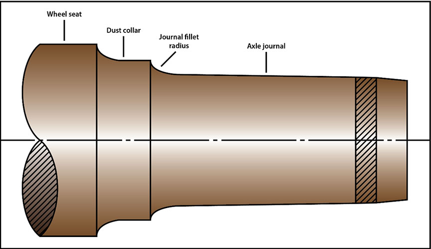
During wheel set assembly, railway wheels are press-fit onto the axle wheel seats. Roller bearings are then press-fit onto the axle journals. The axle wheel seat and journal have different cross-sectional diameters connected by 2 consecutive radii (the dust collar radius and the fillet radius) that transition from the larger-diameter wheel seat to the smaller journal (Figure 5). Both the dust collar radius and the fillet radius require smooth, contoured transitions.
When a wheel set is returned to a wheel shop for reconditioning, if not enough tread material remains for reprofiling,Footnote 10 the wheels are pressed off the axle and the axle is inspected. If the axle meets reconditioning criteria, it qualifies as a secondhand unmounted axle.
New wheels and new or reconditioned roller bearings can be applied, and the wheel set assembly can then be returned to service. Using this process, axles can remain in service for up to or beyond 40 years and can have a number of wheels applied during that time.
1.7 Laboratory examination of broken axle
The broken axle from car CNA 194141 was recovered and sent to the TSB Engineering Laboratory for metallurgical examination and failure analysis.
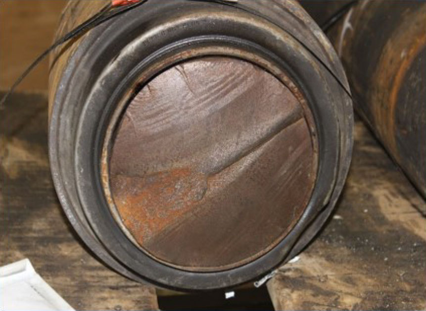
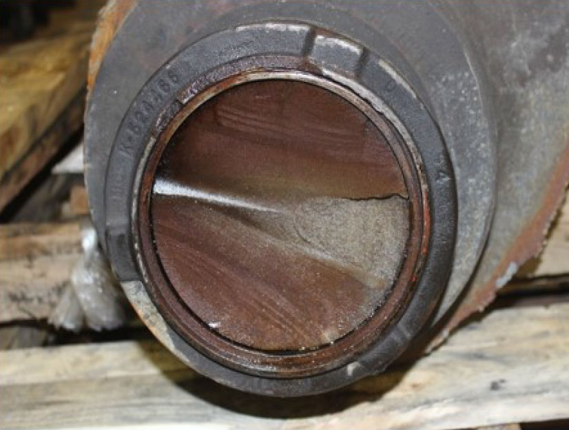
The axle had fractured between the L1 bearing seal wear ring and the backing ring, at the location where the axle journal merges into the fillet. As a result, the journal (with the bearing) separated from the rest of the assembly (Figure 6).
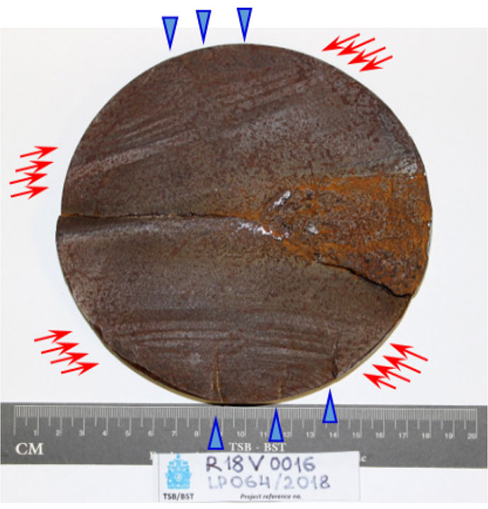
The fracture was due to fatigue cracking in the journal near the fillet. Crack arrest lines (beach marks) were present on the relatively smooth areas of the fracture surface (Figure 7).
The multiple ratchet marks at the edge of the fracture surface indicate multiple fatigue origins on the opposite sides of the axle journal cylindrical surface. Fatigue cracks propagating from these origins had merged, forming 2 large fatigue cracks propagating toward each other (Figure 8 and Figure 9).
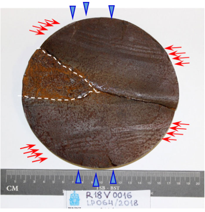
These fatigue cracks met approximately at the middle of the cross-section. The axle eventually failed in overstress when the remaining cross-section could no longer bear the load. The area of overstress fracture (the irregular sector delineated in Figure 8) was about 13% of the total fracture surface area.
The fracture surface features, such as 2 fatigue areas propagating towards each other from the opposite sides, indicate that the rail car axle failed due to reverse bending fatigue. The extent of the fatigue regions with a small final overstress area suggests that the amplitude of the cyclic load driving the crack was relatively low. Multiple fatigue origins suggest that a general stress condition of the axle, rather than any one particular surface defect, caused the fatigue cracking and the axle failure.
The fracture occurred in the journal near the fillet. Journals have the smallest diameter in the axle, and the weight of the rail car is transferred to the wheels through the journals. The journals flex cyclically as wheels roll along the rails, with most of the resulting mechanical stress occurring near the small ends of the fillets.
The occurrence axle conformed to the specification requirements, including the following:
- The axle steel hardness was measured by the Rockwell B method. The results were 85.4 ± 1.2 HRBW, which is within the typical range for class F rail car axles.
- A sample, cut from the axle near the fracture location, was polished and etched with 2% nital. A uniform equiaxed ferrite-perlite microstructure typical for axle steel was observed under an optical light microscope. The grain size, estimated using the ASTM International comparison procedure,Footnote 11 was number 7, which satisfies the specified requirement of a grain size of 5 or finer.Footnote 12
Rail car axles, including the journals, are designed to withstand normal operational loads. Because the occurrence axle conformed to the required specifications, it is likely that the axle had been subjected to abnormal cyclic loading. Abnormal cyclic loading can occur under a number of situations, including a wheel tread defect or general out-of-roundness; a displaced, worn, broken, or wrong-size adapter; or uneven loading from truck components due to truck deformation. Because these components, including the wheels, could not be examined, the exact cause of the fatigue cracking in the axle could not be determined.
1.8 Other similar occurrences
Over the previous 10-year period (2008–2017), there were 23 derailments on CN and Canadian Pacific Railway track caused by a broken axle (Appendix A). In 9 of these derailments (39%), the axle had failed near the journal fillet radius.
The TSB previously investigated 3 other derailments involving axle failures in the journal fillet radius.Footnote 13
1.9 Environmental information
Both Environment and Climate Change Canada and the British Columbia Ministry of Environment and Climate Change Strategy (BCMOECCS) attended the site.
The BCMOECCS monitored the clean-up activities conducted by CN's environmental contractor to ensure that the clean-up and recovery actions met regulatory requirements.
The primary effect on the riparianFootnote 14 habitat was due to the physical disturbance associated with the derailment and response. At the time this report was published, site remediation work was nearing completion. Follow-up surveys were to be conducted to evaluate the success of the revegetation activities and the success in reaching the riparian recovery targets.
1.10 TSB laboratory reports
The TSB completed the following laboratory reports in support of this investigation:
- LP064/2018 – Failure Analysis – Rail Axle
2.0 Analysis
No track infrastructure or train-handling issues contributed to the occurrence. The analysis will focus on the broken axle and the inspection of the journal fillet radius.
2.1 The occurrence
The train derailed when the 52nd car (CNA 194141) sustained a broken axle. In the ensuing derailment sequence, the 2 cars ahead and 24 cars behind car CNA 194141 also derailed.
The axle on car CNA 194141 broke as a result of fatigue cracking in the journal fillet radius. Fatigue cracks from multiple origins had merged, forming 2 large fatigue cracks that propagated towards each other. These fatigue cracks met at about the middle of the axle cross-section. When the small remaining axle cross-section could no longer support the load, the axle failed in overstress.
The occurrence axle conformed to the specification requirements. Therefore, it is likely that the axle had been subjected to abnormal cyclic loading. There could be several reasons for abnormal cyclic loading, including a wheel tread defect or general out-of-roundness; a displaced, worn, broken, or wrong-size adapter; or uneven loading from truck components due to truck deformation. Because these components, including the wheels, could not be examined, it was not possible to determine the exact case of fatigue cracking in the axle. While fatigue cracks at the journal fillet radius of an axle are known to result from abnormal cyclic loading, the exact cause of the fatigue cracking could not be determined.
2.2 Inspection of the journal fillet radius
Rail car axles are subjected to heavy loads, which will affect their fatigue resistance. The axle journal is the primary weight-bearing area of the axle. The journals are outboard of the wheel seats and have a smaller diameter than the dust collar and the wheel seat areas of the axle. As a result, the journal fillet radius is subject to high loading and flexing during normal service operations, with the highest loading occurring at the root of the journal fillet radius as it transitions to the reduced cross-section of the journal surface.
Axle fatigue cracks in the journal fillet radius are not detectable during routine safety inspections, as this part of the axle is concealed by the roller bearing backing ring. Visual inspection in the journal fillet radius is therefore possible only during wheel and roller bearing replacement, or during axle reconditioning. At that time, magnetic particle testing is required by the Association of American Railroads Manual of Standards and Recommended Practices.
In this occurrence, the journal fillet radius of the subject axle was last available for inspection in 2014 when reconditioned bearings were applied. Visual and magnetic particle testing of the journal fillet radius was performed at that time. No anomalies were noted.
This occurrence demonstrates that fatigue cracks can develop in the journal fillet radius and progress to failure, even when the opportunity has been taken to perform visual inspection and conduct magnetic particle testing. Without alternate strategies to identify fatigue cracks in the journal fillet radius or to predict the likelihood of cracks developing, problematic axles might not be removed from service in a timely manner, increasing the risk of broken-axle derailments.
3.0 Findings
3.1 Findings as to causes and contributing factors
- The 52nd car (CNA 194141) sustained a broken axle, leading to the derailment of 27 cars.
- The axle on car CNA 194141 broke as a result of fatigue cracking in the journal fillet radius, but the exact cause of the fatigue cracking could not be determined.
- Fatigue cracks from multiple origins had merged, forming 2 large fatigue cracks that propagated towards each other. These fatigue cracks met at about the middle of the axle cross-section.
- When the small remaining axle cross-section could no longer support the load, the axle failed in overstress.
3.2 Findings as to risk
- Without alternate strategies to identify fatigue cracks in the journal fillet radius or to predict the likelihood of cracks developing, problematic axles might not be removed from service in a timely manner, increasing the risk of broken-axle derailments.
3.3 Other findings
- Fatigue cracks at the journal fillet radius of an axle are known to result from abnormal cyclic loading.
4.0 Safety action
4.1 Safety action taken
The Board is unaware of any safety action that has been taken as a result of this occurrence.
This report concludes the Transportation Safety Board of Canada's investigation into this occurrence. The Board authorized the release of this report on . It was officially released on .
Appendices
Appendix A – Occurrences on Canadian National Railway and Canadian Pacific Railway involving broken axles (2008–2017)
| Car number | Gross rail load (thousand pounds) | Occurrence date | Fracture location | Axle size | |
|---|---|---|---|---|---|
| 1 | CN 111764 | 286 | 2017-12-02 | Axle body | 6.5 |
| 2 | CN 100961 | 286 | 2017-06-12 | Axle body | 6.5 |
| 3 | CIGX 802029 | 286 | 2017-02-27 | Axle body | 6.5 |
| 4 | AEX 15834 | 286 | 2017-02-23 | Axle body | 7.25 |
| 5 | SMW 842980 | 286 | 2016-10-06 | Axle body | 6.5 |
| 6 | RRRX 182944 | 286 | 2016-01-24 | Axle body | 6.5 |
| 7 | PROX 72733 | 286 | 2015-09-03 | Journal fillet | 6.5 |
| 8 | SAMX 11692 | 286 | 2015-02-06 | Journal fillet | 6.5 |
| 9 | CN 110803 | 286 | 2014-07-16 | Axle body | 6.5 |
| 10 | DME 51073 | 286 | 2014-04-26 | Journal | 6.5 |
| 11 | IC 245948 | 286 | 2013-09-24 | Journal fillet | 6.5 |
| 12 | CP 964088 | 286 | 2013-08-13 | Journal fillet | 6.5 |
| 13 | CP 965153 | 286 | 2013-07-03 | Axle body | 6.5 |
| 14 | CGTX 22169 | 286 | 2013-02-10 | Axle body | 6.5 |
| 15 | UTLX 900665 | 286 | 2013-02-03 | Journal fillet | 6.5 |
| 16 | IC 798025 | 286 | 2012-05-15 | Journal fillet | 6.5 |
| 17 | CGTX 22127 | 286 | 2011-07-26 | Journal | 6.5 |
| 18 | IC 799596 | 268 | 2011-06-13 | Axle body | 6.5 |
| 19 | DMIR 70069 | 268 | 2010-10-15 | Axle body | 6 |
| 20 | GTW 517872 | 286 | 2010-03-02 | Axle body | 6.5 |
| 21 | CP 384929 | 286 | 2010-01-15 | Journal fillet | 6.5 |
| 22 | IC 6135 | 286 | 2008-11-07 | Axle body | 6.5 |
| 23 | RG 310 | N/A | 2008-04-16 | Axle body | 6.5 |