Main-track train derailment
Canadian Pacific Railway Company
Freight train 516-380
Mile 43.66, Sutherland Subdivision
Guernsey, Saskatchewan
The Transportation Safety Board of Canada (TSB) investigated this occurrence for the purpose of advancing transportation safety. It is not the function of the Board to assign fault or determine civil or criminal liability. This report is not created for use in the context of legal, disciplinary or other proceedings. See Ownership and use of content. Masculine pronouns and position titles may be used to signify all genders to comply with the Canadian Transportation Accident Investigation and Safety Board Act (S.C. 1989, c. 3).
Summary
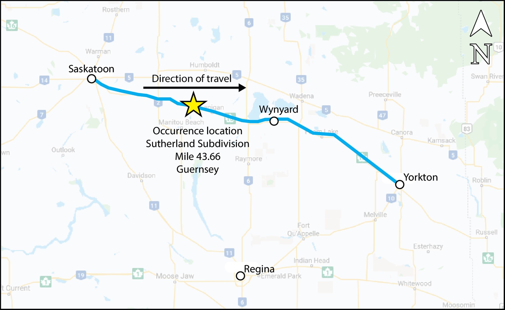
On 06 February 2020, Canadian Pacific Railway Company freight train 516-380, a unit train carrying petroleum crude oil (UN1267, Class 3, Packing Group I), was proceeding eastward on the Sutherland Subdivision at about 44 mph when a train-initiated emergency brake application occurred near Guernsey, Saskatchewan. A subsequent inspection determined that 32 DOT-117J100-W tank cars had derailed near the Bloomfield Road public crossing at Mile 43.66, destroying about 300 feet of track. Thirty of the derailed cars released about 1.75 million L of crude oil. A fire ensued. Approximately 85 residents of Guernsey were evacuated, and Highway 16 was closed. There were no injuries.
1.0 Factual information
On 06 February 2020 at about 0400,Footnote 1 Canadian Pacific Railway Company (CP)Footnote 2 train 516-380, a unit train carrying petroleum crude oil (UN1267, Class 3, Packing Group I), departed from Sutherland Yard in Saskatoon, Saskatchewan (Mile 109.7 on the CP Sutherland Subdivision), destined for Noyes, Minnesota, in the United States (U.S.), via Winnipeg, Manitoba. The train had originated in Rosyth, Alberta (Mile 126.0 on the CP Hardisty Subdivision).
The train consisted of 2 head-end locomotives, a tail-end locomotive, 104 DOT-117J100-W (DOT-117J) specification tank cars loaded with petroleum crude oil, and 2 covered hopper cars loaded with sand (buffer cars)Footnote 3 that separated the crude oil cars from the head-end locomotives. The train weighed approximately 15 000 tons and was 6500 feet in length. It was designated as a key train Footnote 4 operating on a key route. Footnote 5 The train was inspected by a certified car inspector and received a No. 1 air brake test Footnote 6 before departing Sutherland Yard.
The crew consisted of a locomotive engineer and a conductor. Both crew members were qualified for their positions, met fitness and rest requirements, and were familiar with the territory.
1.1 The occurrence
At about 0606, while proceeding eastward at 44 mph on the Sutherland Subdivision, a train-initiated emergency brake application occurred while the head end of the train was passing over the Bloomfield Road public crossing at Mile 43.63 and tail end over the east wye switch at Mile 43.66, near Guernsey, Saskatchewan (Figure 1). Once the train stopped, the crew observed a large fire behind them and called the rail traffic controller. They then separated the head-end locomotives from the rest of the cars and moved to a safe location.
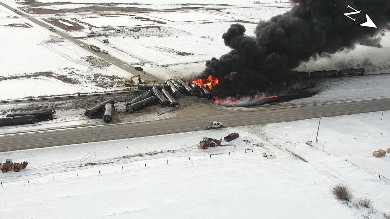
An inspection of the train determined that 32 tank cars (the 31st to the 62nd car behind the head-end locomotives) had derailed, 30 of which were breached. Approximately 1.75 million L of crude oil were released. The product ignited and resulted in a large fire (Figure 2). There were no injuries reported.
1.2 Weather
The temperature at the time of the occurrence was about −15 °C.Footnote 7
1.3 Site examination
The derailment site (where the cars came to rest and the track was damaged) began at the east wye switch of the spur that leads southward to a nearby potash mine and continued eastward for about 500 feet over the Bloomfield Road public crossing at Mile 43.63.
Bloomfield Road is a 2-lane gravel road that intersects the rail line at approximately 85 degrees. The crossing is oriented in a north-south direction and is protected by railway crossing signs.
The track in the area runs parallel to Highway 16 (Yellowhead Highway), which is located about 130 feet north of the rail line. The Yellowhead Highway, Bloomfield Road, and the railway tracks are all elevated above the nearby countryside.
The position of the derailed tank cars was as follows (Figure 3):
- The first 9 tank cars (linesFootnote 8 31 to 39) had derailed on the eastern side of the crossing.
- The next 21 tank cars (lines 40 to 60) had derailed on the crossing or west of it; they were perpendicular to the track, in an accordion fashion, except cars in lines 53 and 57, which came to rest mostly south of the track.
- The last 2 tank cars (lines 61 and 62) were derailed upright on the track; car in line 61 was over the east wye switch.
Because of the topography of the site, crude oil pooled on both sides of the crossing. The oil on the west side was first to ignite. The crossing acted temporarily as a berm but the fire propagated to the east side.

About 300 feet of track extending eastward from the east wye switch was destroyed. The track leading up to the derailment site was inspected and no impact marks were observed on the track structure.
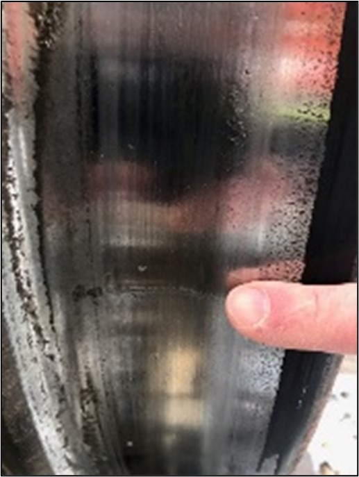
Impact marks were observed on the north-side wheel treads of tank cars located in lines 28, 29, and 30 (Figure 4). The impact mark on the tread of a wheel from the north side of the 28th car began at the flange and extended perpendicular across the wheel tread for about 2¼ inches.
Several rail pieces from the west side of the crossing were recovered and sent to the TSB Engineering Laboratory in Ottawa, Ontario, for analysis.
The size and intensity of the fire resulted in necessary remediation efforts by the first responders that disturbed the post-accident site, displacing cars and rail, and hampered the TSB investigation data-gathering phase.Footnote 9
1.3.1 Derailment zones
Examination of previous tank car derailmentsFootnote 10,Footnote 11,Footnote 12 indicates that, when crude oil unit trains derail, there are typically 3 major zones within a derailment area:Footnote 13
- The initial zone, zone 1, is where tank cars derail at the head end or leading portion of the derailment and generally scatter randomly. This is represented by tank cars located in lines 31 to 36 in this occurrence. In this zone, tank car bodies often separate from their truck assemblies and slide until they encounter obstacles that will slow their movement. Often, cars in this zone retain excellent shell integrity during the derailment and there is usually less tank deformation and smaller impact dents or breaches.
- The 2nd zone contains the main body of the derailment. This is the zone where tank cars generally jackknife, align side by side, and/or stack up. This is represented by cars located in lines 37 to 60 in this occurrence. Tank cars in this zone usually account for the majority of the breaches and volume of product released. This can be attributed to the large dynamic forces that the tank cars experience in this zone. The first car in this zone acts as an anchor as it derails and slows or stops the forward progress of the subsequent derailing tank cars. The impact forces resulting from the trailing tank cars’ momentum impart large loads on the derailed tank cars that have come to rest and will often result in large tank deformations or punctures.
- The 3rd zone is at the tail end of the derailment. Similar to zone 1, the remaining tank cars that derail in this zone usually scatter randomly but do not stack up. This is represented by cars located in lines 61 and 62 in this occurrence. As the cars derail in the main body of the derailment, energy is dissipated through the impacts up to the time that the tank cars separate from each other. The impacts and associated reduction in the speed of the trailing tank cars reduce the impact forces and typically result in less tank damage and associated product loss.
Different types of damage, ranging both in severity and the amount of product released, have been observed in each of the 3 derailment zones. The reasons for the amount of damage sustained by each of the derailed tank cars vary, but common elements include the speed of the train at the time of the derailment, the size of the derailment area, the topography of the derailment area, and the temperature at the time of the derailment.
1.4 Emergency response and site remediation activities
Once notified of the occurrence, CP immediately activated emergency response plan ERP2-1933-067 that was provided by ConocoPhillips Company Canada, the owner and shipper of the crude oil. The plan set forth the framework and procedures to safely and effectively respond to all types of emergencies, including those involving dangerous goods. It also served as the Emergency Response Assistance Plan filed with Transport Canada (TC) under the Transportation of Dangerous Goods Act.
The Royal Canadian Mounted Police, CP police, the Lanigan and the Humboldt fire departments, and emergency medical services personnel responded to the occurrence and were on site within minutes of being notified. The Saskatchewan Ministry of the Environment and an environmental private contractor also attended.
A unified command structure was put in place, which included representatives from the Saskatchewan Ministry of Environment, the Lanigan Fire Department, and CP.
The site was immediately secured and Highway 16 was closed to through traffic. Approximately 85 residents in the nearby town of Guernsey were evacuated.
Air quality monitoring began at about 0720 and continued throughout the day to ensure the safety of personnel working at the site.
Berms were created to contain the flow of released oil. Fire-control tactics, which included water to cool the tank cars and foam to extinguish fires, were implemented as soon as it was safe to do so. Tank cars not on fire were dragged clear. The tail-end cars of the train were pulled to a nearby siding.
During the evening of 06 February 2020, movement of the cars west of the crossing resulted in one car sustaining a puncture by a tractor; the punctured car released a stream of burning oil, which ignited the pool of crude oil on the east side of the crossing, resulting in a pool oil fire that engulfed many of the cars east of the crossing.
Once the fires had been extinguished, the remaining oil was either vacuumed from the ground or transloaded from the rail cars and hauled away.
1.5 Recorded information
1.5.1 Locomotive forward-facing video camera
The ride was reported as being “rough” over the east wye turnout and leading up to the crossing. However, a review of the forward-facing video camera recording on the train’s lead locomotive (CP 7016) showed that the track was intact as the train approached the Bloomfield Road crossing.
1.5.2 Locomotive event recorder
A review of the data from the event recorder in the lead locomotive shows that:
- At 0605:52, the lead locomotive entered the crossing at Mile 43.63.
- At 0606:23, a train-initiated emergency brake application was registered while the lead locomotive was at Mile 43.24 and travelling at 44 mph with the throttle in position 4 and the train brakes released.
- At 0607:20, the lead locomotive came to a stop at Mile 42.84 after travelling roughly 2100 feet in emergency.
Based on the emergency brake application propagation rate, the train line separation occurred between the 30th car and 31st car while these cars were on the crossing at Mile 43.63.
1.5.3 Wayside detectors
After departing Sutherland Yard, the train passed several wayside hot box detectors with no exceptions noted.
The train had also travelled over a wheel impact load detector on 05 February 2020 at Keppel, Saskatchewan (Mile 52.4 on the Wilkie Subdivision); no abnormal reading was recorded.
1.6 Subdivision information
The Sutherland Subdivision is a main track that extends westward from Wynyard, Saskatchewan (Mile 0.0), to Saskatoon (Mile 113.5).
Train movements on the Sutherland Subdivision are governed by the occupancy control system, as authorized by the Canadian Rail Operating Rules, and dispatched by a CP rail traffic controller located in Calgary, Alberta.
From 2017 to 2019, freight traffic, including crude oil, had been trending upward (Table 1).
| Year | Freight traffic volume (million gross ton-miles per mile) | Car loads of crude oil | Crude oil volume (L) |
|---|---|---|---|
| 2015 | 16.2 | 11 039 | 1 214 290 000 |
| 2016 | 12.8 | 1936 | 212 960 000 |
| 2017 | 16.0 | 10 523 | 1 157 530 000 |
| 2018 | 22.5 | 49 711 | 5 468 210 000 |
| 2019 | 26.1 | 77 312 | 8 504 320 000 |
1.7 Track information
The Sutherland Subdivision is Class 4 track under the Rules Respecting Track Safety, also known as the Track Safety Rules (TSR). In the vicinity of the derailment, the authorized speed for freight trains was 45 mph.
The track was tangent single main track oriented in a northwest-southeast direction and relatively level. It consisted of 115-pound continuous welded rail (CWR) manufactured by Algoma Steel Inc. The rail had been previously used at another location and was installed on the Sutherland Subdivision in 1985. It rested on 14-inch double-shouldered tie plates and was fastened to hardwood ties. There were 57 ties per 100-foot section of track, and they were box anchored every tie. The ballast was round rock approximately 4 inches in diameter. In areas where the ballast had been upgraded, 4.5-inch crushed rock ballast was used.
1.7.1 Track renewal program
Between 2015 and 2019, CP undertook several track renewal programs for Class 4 track on its northern main line corridor, which includes the Sutherland Subdivision.
In the vicinity of the derailment, the gauge was restored for about 5900 feet of track between Mile 42.8 and Mile 43.9 in May 2019. In October 2019, the rail between Mile 42.5 and Mile 45.8 was destressed, and approximately 1000 ties were installed between Mile 41.0 and Mile 46.0.
In the same period, about 11 000 of the 15 840 feet of track between Mile 42.8 and Mile 45.8 was surfaced. The maintenance records were not detailed enough to confirm that the track between the east wye switch and the crossing had been surfaced.
1.8 Track inspections
The TSR set forth the minimum regulatory requirements for track maintenance and inspection.
According to the TSR, Class 4 CWR track with annual traffic greater than 15 million gross tons (MGT) must be visually inspected (on foot or in a track vehicle) at least twice weekly. Footnote 14
The TSR also require that Class 4 CWR track with annual traffic between 15 and 35 MGT receive:
- an electronic geometry car inspection by a heavy geometry inspection vehicle twice annually,Footnote 15,Footnote 16
- a rail flaw detection inspection 3 times annually,Footnote 17
- a walking turnout inspection monthly,Footnote 18 and
- a detailed turnout inspection annually.Footnote 19
1.8.1 Visual inspection
In addition to the regulatory requirements, CP required the track to be visually inspected 24 hours prior to the arrival of a crude oil train, or when temperatures were at −25 °C or below.
From 29 January 2020 to the date of the occurrence, visual inspections were performed daily. The most recent visual inspection was undertaken on 05 February 2020 and no defects were noted in the vicinity of the derailment area.
1.8.2 Geometry inspection
In 2019, CP’s heavy track geometry vehicle inspections of the Sutherland Subdivision were performed in March, August, and November, exceeding the number of inspections required by the TSR. During these inspections, the following geometry defects were noted from Mile 43.63 to Mile 43.66:
- 29 March 2019: 5 priority defects
- 21 August 2019: 9 priority defects, 1 near urgent defect, 1 urgent defect
- 26 November 2019: no priority defects were listed in the defect report
Geometry defects are classified by CP as urgent, near urgent, and priority. Urgent defects are those that do not meet the regulatory requirements and must be protected with a slow order until corrected. Near urgent defects must be inspected and corrected as soon as possible. Priority defects must be inspected and monitored to ensure they do not become urgent defects.
Following the 21 August 2019 inspection, a 25 mph slow order was placed on the track, followed by a 40 mph slow order that lasted until the urgent defect was corrected on 04 December 2019.
During the 26 November 2019 inspection from Mile 43.63 to Mile 43.66, the readings were considered as “invalid” because of snowing conditions that interfered with them. CP consequently followed the instructions provided in the TSR for situations where the track cannot be inspected at the required interval:
4.3 Missed Segment of Electronic Geometry Inspection
- If a portion of track cannot be inspected at the required interval, the railway must, before the expiration of time or tonnage limits:
- Inspect that segment of track with a light geometry inspection vehicle and be governed by the results of that inspection or perform an additional visual inspection per week until the required track geometry inspection frequency can be met and, in the case of Class 3 to Class 5 track the next required track geometry inspection must be completed with a heavy geometry inspection vehicle, or
- Reduce class of track to bring the track into compliance until such time as a valid track geometry inspection can be made.Footnote 20
1.8.3 Rail flaw detection inspection
In 2019, CP conducted 7 rail flaw detection inspections. The most recent inspection occurred on 17 December 2019. No defects were detected in the vicinity of the occurrence.
1.8.4 Turnout inspections
The last annual detailed turnout inspection occurred on 12 June 2019. A detailed inspection evaluates, through measurement, observation and use, the condition of the track (including the ballast, rails, and ties), and all components of the switch to ensure the turnout is kept in compliance with the standards and that deviations from the standards are protected or brought back into compliance. No defects were noted.
The last monthly walking inspection of the turnout was undertaken on 20 January 2020. The point on the frog was observed to be damaged. The turnout was scheduled to be repaired before 20 February 2020.
1.8.5 Additional Canadian Pacific inspections
In addition to the minimum regulatory requirements for track maintenance and inspection specified in the TSR, CP implemented the following additional inspections:
- Vehicle track interaction (VTI) inspections
- Autonomous track geometry measuring system (ATGMS) inspections
- Walking joint bar inspections
1.8.5.1 Vehicle track interaction inspections
To supplement track geometry inspections, CP uses some locomotives to conduct VTI inspections. VTI locomotives are equipped with accelerometers that monitor track conditions and communicate rough spots in the track while in normal train operation. The rough spots are associated with higher-than-usual wheel impact loading that could lead to a potential broken rail.
The most recent VTI inspection was undertaken on 19 October 2019. There were no VTI events that required attention in the vicinity of the derailment.
1.8.5.2 Autonomous track geometry measuring system inspections
ATGMS are specially equipped box cars that operate in revenue train service. This enables more frequent geometry testing and identifies emergent geometry conditions. The ATGMS supplements the track evaluation cars currently in operation. The most recent ATGMS inspection occurred on 09 October 2019. There were no conditions that required attention in the vicinity of the derailment.
1.8.5.3 Walking joint bar inspections
CP implemented bi-annual joint bar inspections for Class 4 CWR track with an annual tonnage between 15 and 35 MGT, including the Sutherland Subdivision. These walking joint bar inspections are specifically looking to identify cracked/broken joint bars as well as loose, broken, or missing bolts. The last joint bar inspection was performed on 06 December 2019, and no joint bar defects were found in the vicinity of the derailment.
1.9 Rail replacement in continuous welded rail territory
When CWR is worn or damaged and needs replacement, the defective section of rail is typically cut out and a replacement rail (plug rail) is installed. A plug rail can be new rail or rail that was removed from service and found suitable for reuse. The plug rail can be welded to the parent rail or secured using bolted joints.
To join plug rails by bolted joint, a joint bar is fitted on each side of the rail ends. The assembly is fastened together, through the web of the rails, with 4 or 6 bolts.
1.9.1 Requirements for installing used rails as plug rails
When rail is removed from service and is to be used as plug rail, it is visually inspected, ultrasonically tested, measured for head wear and flange wear, and then stacked on a rail rack to await installation. These measures reduce the risks of re-introducing a defective rail back into service.
Regarding the reuse of rail, CP’s Red Book of Track & Structures Requirements (the Red Book) states, in part:
6.1.8 Marking Rail Removed from Track
[…]
- Rail determined suitable for re-use over which 10 MGT or less traffic has run over the rail since it was last ultrasonically tested is to be marked with the letters UTV (for ultrasonic test verified) and with the date of the last ultrasonic test on the web of the rail in 2” or greater letters with white permanent marker.
- Rail determined suitable for re-use which has not been ultrasonically tested, or over which more than 10 MGT traffic has run over the rail since it was last ultrasonically tested is not to be installed and is to be left for future ultrasonic testing. The tester marks the rail with the letters UTT (for ultrasonic test tested) and with the date of the test on the web of the rail in 2” or greater letters with white permanent marker.
- Rail planned for re-use, which is not marked UTT or UTV and for which the testing history is not known, may only be installed in track with the approval of the Director Track Standards, and if installed requires the application of a speed restriction of not more than 25 mph or the maximum speed for the class of track concerned, whichever is less, until the rail has been tested for internal defects. Footnote 21
1.9.2 Rail neutral temperature
To prevent pull-aparts and track buckles in CWR track, it is important to manage the internal stresses in the rail, including when the rail is cut and sections are added or removed. Temperature variations generate internal thermal stresses in CWR. At the rail neutral temperature (RNT), the rail is free of any tensile or compressive stress. Whenever the temperature of the rail diverges from its neutral temperature, internal stresses develop—compressive when the temperature is above the RNT and tensile when it is below. Excessive compressive forces can cause track buckling, while excessive tensile forces due to contraction can lead to pull-aparts (joint bar failures or rapid rail fractures).
Rail is preferably installed or adjusted at a specific temperature set for the climatic conditions of the subdivisions at which the rail remains relatively stress-free all year round, considering the regional ambient temperature extremes to which it will be exposed. This temperature is known as the preferred rail laying temperature (PRLT). On the Sutherland Subdivision, the PRLT is 95 °F. When the RNT differs from the PRLT by a prescribed amount, the rail length should be adjusted accordingly to reset the stress in the rail, a process called destressing.
Temperature swings, track maintenance activities, and traffic-induced movements of the rail can cause a change or redistribution of the rail’s internal stresses, thus modifying the RNT. In general, the RNT decreases over time and becomes different from the PRLT.
According to the Red Book, the estimated RNT following a rail replacement due to a pull-apart or a rail break can be estimated using the measured rail temperature and the effective rail gap. Footnote 22, Footnote 23
1.9.3 Plug rails installed near the occurrence location
1.9.3.1 Plug rail installed on 14 January 2020
During a visual inspection before the passage of a crude oil train on 14 January 2020, a rail break was detected in the north rail of the track just east of the east wye switch at Mile 43.66. The break was located near a joint, 6 feet (3 to 4 ties) from the east wye switch point.
A 22-foot piece of rail was removed and a plug rail of similar length was installed eastward from the joint. The plug rail did not have any marking (i.e., UTV or UTT) to indicate that it had been inspected for internal flaws as required. The original joint bars were visually inspected as requiredFootnote 24 and reinstalled. The tie plates supporting the joint were shimmed to ensure a proper level.Footnote 25
The work was performed by a team from Sutherland Yard. That same team had changed several broken rails during a cold snap in January 2020.
The air temperature was around −30 °C (−22 °F) at the time of the installation.
1.9.3.2 Plug rail installed on 29 January 2020
On 28 January 2020 and 29 January 2020, TC inspectors inspected the Wilkie and the Sutherland subdivisions and noted multiple instances of plug rails on the Wilkie Subdivision not being ultrasonically tested.
At the end of 29 January 2020,Footnote 26 the 22-foot-long plug rail installed at Mile 43.66 on 14 January 2020 was replaced by a winter Utility team working in dark, windy, sub-zero conditions. Additionally, the crew of a waiting train requested an estimated time of completion, making the team aware of the need to complete the work quickly.
On the day of the installation, the minimum air temperature was around −5 °C (23 °F) at the end of the afternoon and the evening. That evening, the wind was around 20 km/h, resulting in a wind chill factor of −10.Footnote 27
To install the plug rail, the team first dismantled the joints. The bolts were difficult to removeFootnote 28 and a 1.5-inch gap occurred after they were removed. A piece of rail measuring 39 feet and 1.5 inches was cut out of the track and a 39-foot piece of replacement rail, with pre-drilled holes for the joint bars,was installed, extending eastward from the existing west joint and towards the crossing. The plug rail had a “UTT 09/19” marking on the web, indicating that the rail had been tested for internal defects in September 2019.
The original joint bars were visually inspected as required and re-used on the west joint, while 2 new joint bars were installed on the new east joint. The rail was elongated with a heating rope and drift pins were used to align the bolt holes in the rail and in the joint bars. New bolts were used to fasten the joint bars to the rails. The west joint was sitting between 2 ties that were reported to be in good condition; no shims were installed. The original anchors (Improved Fair anchors) were reinstalled.
During the period between the installation of the plug rail and the accident, temperature swings between negatives and positives occurred; on 01 February 2020, the temperature reached 6 °C and then it dropped to −24 °C on 04 February 2020.
The winter utility team that installed the plug rail comprised a foreman, a truck driver, and 2 machine operators. The team foreman was qualified for his position, was familiar with the Red Book, and had participated in rail installations in the past; however, the team’s main regular task was the cleaning of switches and crossings during the winter season. The foreman did not hold a permanent position and was assigned to the production gangs in the summer.
1.9.3.3 Digital Track Notebook database
Whenever rail is installed, the rail temperature, the rail movement, the rail removed, the effective rail gap, and the RNT of the plug rail are recorded in CP’s Digital Track Notebook (DTN) database.
1.9.3.3.1 Plug rail installed on 14 January 2020
The following data were recorded in the DTN database for the 22-foot plug rail installed on 14 January 2020:
- Rail temperature: 2 °F (−17 °C)
- Rail movement: 1.25 inches
- Rail removed: 0 inch
- Effective rail gap: 1.25 inches
- Estimated RNT: 80 °F (27 °C)
1.9.3.3.2 Plug rail installed on 29 January 2020
For the 39-foot plug rail installed on 29 January 2020, the winter utility team foreman completed a CWR maintenance form at the end of his shift and left it at the supervisor office where the information pertaining to the plug rail installation was transferred later to the DTN database. The following data were recorded in the DTN database:
- Rail temperature: 12 °F (−11 °C)
- Rail movement: 1.5 inches
- Rail removed: 1.5 inches
- Effective rail gap: 1.5 inches
- Estimated RNT: 91 °F (33 °C)
Several DTN data fields pertaining to the installation of the 29 January 2020 plug rail are inaccurate. On 29 January 2020, the air temperature gradually decreased from a maximum of 26.6 °F (−3.0 °C) just after midnight to a minimum of 23.4 °F (−4.8 °C) during the end of the afternoon and early evening; therefore, the rail temperature could not have been 12 °F (−11 °C). Footnote 29 Moreover, the effective rail gap should be 3 inches and the estimated RNT should be 125 °F and not 91 °F.
1.10 Examination of the recovered rail pieces
Among the rail pieces received at the TSB Engineering Laboratory, 5 of them were assembled into one contiguous rail length measuring approximately 39 feet, which corresponds to the plug rail installed on 29 January 2020. However, none of the parent rail at either end of the plug rail, nor the joint bars and bolts used to connect the plug rail, were found.
The rail was identified as 115-pound railFootnote 30 manufactured in 1971 by Algoma Steel Inc. The provenance of the rail and its accumulated tonnage are not known. It had between ¼ inch and 5/16 inch of head wear and had 3 holes drilled at each end. A “UTT 09/19” white marking was written on the gauge-side web of one of the rail pieces.
At the west end of the plug rail, the rail exhibited a vertical head crack and a 6.3-inch missing portion of rail head on the gauge side (Figure 5). The overall appearance and orientation of the fracture surface is consistent with either a vertical split headFootnote 31 or a shear break failure. When a vertical split head occurs at a joint, it is categorized as a VSJ (vertical split head joint area).Footnote 32
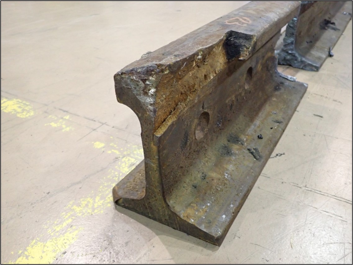
At the same rail end, the remaining head of the rail on the field side had been battered by wheel impacts. On the gauge side, no impact or rubbing marks were visible on the transverse fracture of the rail head. There was also a horizontal crack extending from the rail end to the first bolt hole (Figure 6).
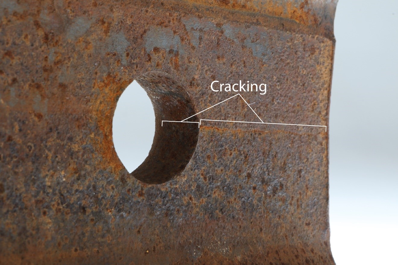
Examinations of the fracture surfaces of the VSJ/shear break and the bolt hole crack found that extensive rubbing and corrosion damage obliterated most of the fracture surface features. It was concluded that the remaining scattered pockets of cleavage facets indicated that both cracks probably led to failure due to brittle overload. The inspection of the fracture surfaces did not reveal signs of fatigue.
Bolt hole cracks are usually the result of “unusual stresses along the edge of the hole from the bolt itself. These stresses may be caused by pumping or swinging joints, improper drilling, excessively worn joint bars or abnormal rail end impacts from rolling stock.”Footnote 33
It was not possible to determine with certainty if the fractures occurred before the derailment or as result of it.
1.11 Rail bolted joints in continuous welded rail territory
Rail joints introduce discontinuities in the geometric and mechanical properties of the rail and are often considered one of the weakest locations in the track structure, making it more susceptible to defects and failures. Once assembled, a bolted joint cannot preserve the continuity of the rail by providing similar strength, stiffness, flexibility, and uniformity as the rail that it joins. Even when a joint is properly supported by sound ties and tamped ballast, its moment of inertia Footnote 34 is only about ⅓ of the value for corresponding non-jointed rail. Footnote 35 Consequently, bolted joints can be subject to high impact loading as rolling stock wheels pass over them. Footnote 36
These impact loads may cause or exacerbate the loosening of the joint bolts. Newly installed bolts, even when properly tightened, can lose from ¼ to ⅓ of their initial preload tension during their first month of installation. Footnote 37 The bolts may loosen more rapidly when a joint is not properly supported. In addition, temperature swings are known to quicken the loosening of bolts in rail joints.
1.11.1 Longitudinal forces in bolted joints
In a properly maintained track, longitudinal forces (thermal forces from temperature changes and train forces from traction and braking) are absorbed by the ballast through the anchoring system and the ties.
In the absence of adequate restraining support by the ballast, ties, and anchors, the bulk of the forces are transferred by the rails through the joints; more precisely, longitudinal forces are transmitted to joint bars through the bolts and by friction between the surfaces of the joint bars and the rail. However, if the bolts are loose, the friction dissipates and the longitudinal forces are transmitted to the joint bars only through the bolts. The resisting force of the joint connection is therefore strongly related to the condition of the bolts.
The resisting force in a joint must be high enough to withstand the combined effect of vertical and longitudinal loads, otherwise the joint will fail. In some cases, failures can occur under the effect of longitudinal thermal forces only, particularly at extreme temperatures.
In support of this investigation, the tensile loads required to cause the failure of the rail and the joint bars for the west joint of the plug rail installed on 29 January 2020 were calculated; the joint connection resisting force and the thermal forces exerted on the joint were also calculated (Appendix A).
The results indicate the following (assuming the joint components were free of defects):
- The tensile load that would have been required to cause the failure of the 115-pound rail was calculated to be greater than approximately 1 598 900 pounds of force.
- The tensile load that would have been required to cause the failure of the joint bars was calculated to be greater than approximately 1 170 000 pounds of force.
- The resisting force of the joint connection is the sum of the forces provided by the friction between the joint bars and the rail, and the shear strength of the bolts. Considering the short length of track over which the relatively low number of anchors supported the 39-foot plug rail, and their holding condition (re-used several times), the resisting force provided by the anchors and track structure (ties and ballast) was negligible. The joint connection resisting force was calculated to be approximately 342 000 pounds, assuming the bolts were tight. If the bolts were loose, the resisting force would be provided only by the bolts and was calculated to be approximately 252 000 pounds.
- The longitudinal thermal force at the time of the occurrence was calculated to be approximately 262 500 pounds; it was calculated to be approximately 298 000 pounds on 04 February 2020 when the temperature was −24 °C (−11.2 °F).
1.12 Dangerous goods
The transportation of dangerous goods Footnote 38 by rail in Canada Footnote 39 and in the U.S. Footnote 40 is governed by federal regulations. In this occurrence, petroleum crude oil, a Class 3 flammable liquid, was being transported in 104 tank cars. Class 3 flammable liquids are dangerous goods whose vapours can form an ignitable mixture with air at or below a temperature of 60 °C (140 °F). These flammable liquids can pose serious hazards due to their volatility and flammability, which are determined by the initial boiling point Footnote 41 and the flash point, Footnote 42 respectively.
Because the volatility and flammability of flammable liquids vary widely, they are grouped together based on these characteristics so that different requirements for packaging, storage, handling, and transportation can be established. According to the Transportation of Dangerous Goods Regulations, Class 3 flammable liquids are divided into 3 packing groups (PG), ranging from PG I (highest hazard) to PG III (lowest hazard). The specific criteria for these packing groups are:
- PG I—if the flammable liquid has an initial boiling point of 35 °C (95 °F) or less at an absolute pressure of 101.3 kPa and any flash point;
- PG II—if the flammable liquid has an initial boiling point greater than 35 °C (95 °F) at an absolute pressure of 101.3 kPa and a flash point less than 23 °C (73 °F); and
- PG III—if the criteria for inclusion in PG I or PG II are not met.
In this occurrence, the petroleum crude oil being transported was listed as a flammable liquid in Class 3, PG I.
1.13 Tank car information
The crude oil was transported in DOT-117J tank cars Footnote 43 in accordance with the Transportation of Dangerous Goods Regulations. DOT-117J tank cars are the newest tank cars built to transport Class 3 flammable liquids, including petroleum crude oil. The tank cars involved in this occurrence were all manufactured by TrinityRail in 2019 and each had an average capacity of about 108 881 L.
The design characteristics of DOT-117J tank cars include a thicker, insulated/thermally protected tank, a full head shield, top fitting protection, and disengaging bottom outlet valve handles (see Appendix B for full details).
1.14 Performance of the DOT-117J100-W tank cars
The TSB laboratory examined the derailed DOT-117J tank cars that were in the main pile-up and had sustained significant damage. All the tank cars involved in this occurrence were equipped with a ½-inch-thick ceramic thermal protection blanket between the tank car shell and jacket.
The following observations were made for the 30 derailed tank cars that lost product: Footnote 44
- 9 lost their entire load,
- 11 lost at least half their load,
- 4 lost less than half their load, and
- 6 experienced some product loss but no obvious breach location was identified, and losses may have been due to pressure relief device activation.
Some of the tank cars were further damaged during remediation activities. These damages occurred when first responders and remediation teams displaced tank cars to combat fires, contain leaks, and recover product. During the damage assessment examination of the tank cars, it was difficult to differentiate between derailment damage and remediation damage.
Many of the shell breaches were punctures consistent with collisions with sharp, relatively small objects (couplers, trucks, bolsters). A few tank cars exhibited fractures due to large crushing damage typically caused when 2 tank car bodies collide.
The head damage ranged from relatively minor dents to deep dents with punctures that breached the head.
Of the 30 cars that lost product, 11 had one or more breaches with features consistent with mechanical shear cutting of the tank shell and/or head. It was not possible to determine if an initial breach existed due to the derailment, which was later enlarged by mechanical shear during remediation efforts.
A breach point could not be identified for 6 cars; however, it is possible that the loss of product was the result of the pressure relief device activating while the tank cars were in the fire, or damaged seals on the bottom outlet valves due to the exposure to intense heat from the fire.
The observed breaches, detailed in Appendix C, are as follows:
- Top fitting breaches and pressure relief device releases (15 cars: 8 confirmed and 7 suspected) Footnote 45
- Shell breaches (11 cars: 8 confirmed and 3 suspected)
- Head breaches (7 suspected)
- Bottom outlet valve releases (5 suspected)
- Manway breaches (3 cars: 2 confirmed and 1 suspected)
Finding: Other
Although the tank cars had been subjected to a pool fire that burned for approximately 19 hours, no thermal tears were observed.
1.15 Other derailments involving tank car unit trains transporting crude oil
Four previous derailments involving tank car unit trains transporting crude oil (1 of them a CP train) were investigated by the TSB from 2015 to 2020. Footnote 46 A total of 138 tank cars loaded with crude oil derailed, releasing a combined total of approximately 6.8 million L of product.
These 4 accidents share some common elements, specifically,
- they all involved crude oil unit trains operating on key routes, and
- they all occurred primarily as a result of inadequate track maintenance and related joint or rail conditions.
1.15.1 TSB investigation R19W0320
Less than 2 months before this occurrence, another crude oil unit train derailed only 5 miles to the west on the Sutherland Subdivision, resulting in a large amount of crude oil being lost and a resulting pool fire that engulfed many of the derailed cars.
On 09 December 2019 at about 0010 Central Standard Time, CP petroleum crude oil unit train 516-398, hauling 99 loaded tank cars and 2 cars loaded with sand, was proceeding eastward at 44 mph on the Sutherland Subdivision when a train-initiated emergency brake application occurred at the Wolverine Road public passive crossing located at Mile 48.85, near Guernsey, Saskatchewan.Footnote 47
Subsequent inspection determined that 1 covered hopper car loaded with sand and 33 tank cars, 9 built to the DOT-117R specification and 24 built to the CPC-1232 specification, loaded with petroleum crude oil had derailed. Twenty of the 33 derailed tank cars were breached and released their contents. The released product ignited, and excess product gathered into a large pool that burned for about 24 hours. Several tank car shells, heads as well as wheels and axles of various cars were melted. Although signs of potential thermal tears were observed, the presence of thermal tears could not be confirmed with any certainty due to the extent of the tank car damage.
There were no injuries, and no evacuation was required. The temperature at the time of the accident was −19 °C (−2 °F).
It is estimated that a total of approximately 1.76 million L of petroleum crude oil was released to surface and atmosphere, which was about 57% of the total volume that was transported in the 33 derailed tank cars.
The Board found that:
- The derailment occurred when the CP crude oil unit train traversed a gap in the south rail while traveling eastward on the Sutherland Subdivision, near Mile 48.86.
- The south rail head was exposed after an undetermined length of the rail had broken away and separated from the track, when the south rail likely failed under a previous train, prior to the arrival of the occurrence train.
- The track components (anchors, ties, and ballast) did not provide adequate resistance to the rail longitudinal tensile forces initiated by the cold weather, which contributed to a rail that broke under normal service loads prior to the arrival of the train.
1.16 Recent National Transportation Safety Board recommendations for DOT-117J100-W tank cars
On 26 September 2023, the U.S. National Transportation Safety Board (NTSB) released a synopsis of its final report on the derailment of a BNSF Railway Company train that occurred on 08 January 2022, in Oklaunion, Texas. Footnote 48 The train derailed 37 DOT-117J tank cars carrying denatured ethanol Footnote 49 while travelling at a speed of 50 mph. Approximately 2.28 million L of denatured ethanol was released from 28 of the 37 derailed tank cars. The ethanol ignited and burned uncontrolled for about 4 hours, resulting in a pool fire.
The report contains some findings Footnote 50 specifically related to some DOT-117J deficiencies observed during the NTSB investigation:
- “Gaskets currently used in DOT-117J tank car service equipment may be made of materials vulnerable to thermal damage when exposed to fire, which can lead to the release of hazardous material.”
- “Using gaskets with higher service and survival temperatures would likely increase the fire exposure survival time of DOT-117J tank car service equipment in flammable liquid service and reduce the severity of hazardous materials releases”.
- The Pipeline and Hazardous Materials Safety Administration’s 2016 “expansion of existing thermal protection system regulations from pressure tank cars to non-pressure DOT-117J tank cars likely did not account for the design differences between these types of tank cars, thus a DOT-117J tank car certified as compliant with regulations may have deficient thermal protection because its service equipment may not be protected by its thermal blanket.”
- “The mechanical breach of tank car TILX 731751 between the tank head material and the front sill pad occurred because the window weld between the front sill pad and the tank continued to provide a load path between the tank head and the stub sill while the head brace remained attached to part of the front sill pad, leading to a local stress state that exceeded the strength of the tank head material.”
- “Because welds between the head brace and front sill pad exceeded their design sizes, the strength of the head brace attachment weld for tank car TILX 731751 likely exceeded the load-carrying capability of the underlying front sill pad, reducing the probability of the weld failing as intended when placed under high loads, such as the ones that occur during a derailment, and resulting in the tank car being mechanically breached.”
As a result of this investigation, the NTSB recommended Footnote 51 that:
- The Federal Railroad Administration and the Pipeline and Hazardous Materials Administration work together “to develop and publish both benchmarks and thermal performance standards for gaskets used in tank cars transporting flammable liquids.”
- The Pipeline and Hazardous Materials Administration “revise the DOT-117J tank car specification to ensure that these tank cars use appropriate thermal protection systems, and that the Association of American Railroads update its certification process to ensure that tank cars comply with this revised specification.”
- “The Association of American Railroads create an inspection standard in the Manual of Standards and Recommended Practices for rejecting oversized welds at key points on tank car underframes.”
1.17 Studies on severity of derailments involving dangerous goods
In December 2019, the National Research Council Canada released report ST-R-TR-0118, entitled Study on the Factors that Increase the Severity of the Outcomes for Derailments Involving Dangerous Goods and Identification of Mitigation Measures. Footnote 52 This undertaking was commissioned by TC in response to TSB Recommendation R17-01, which resulted from TSB Rail Transportation safety investigation report R15H0013. The Board recommended that TC conduct a study on the severity of the outcomes for derailments; identify appropriate mitigating strategies, including train speeds, for various train risk profiles; and amend the Rules Respecting Key Trains and Key Routes. In March 2021, the Board considered the response to Recommendation R17-01 to be Fully Satisfactory.
The study noted that there is a complex relationship among train speed, train length, and mechanism of derailment, all of which can influence the severity of a derailment’s outcome.
The study also noted that derailments caused by broken rails, rail welds, or broken joint bars had a much higher occurrence rate and derailed more cars per accident for a given speed. As speed increased, these types of derailments resulted in more severe accidents compared to other accident causes.
The review of the Rules Respecting Key Trains and Key Routes within the study determined that the rules could be improved to account for the track repair and maintenance processes of railways in Canada. The study concluded that sections 5.3 and 5.4 of the Rules concerning the joint bars should have a procedure in place for the temporary installation and inspection of joint bars and plug rails in CWR territory and that the procedure should include a frequency at which the temporary joint bar and/or plug rail will be inspected until it is permanently repaired. As well, the study recommended that the inspection frequency should be related to traffic volumes and the presence of key trains in the traffic.
The Rules Respecting Key Trains and Key Routes were amended on 22 August 2021 to require companies to develop a maintenance and inspection plan for permanent rail joints and temporary rail joints. The plan must detail the frequency and methods of inspection, time limits for the retention of temporary rail joints until permanently repaired and include a requirement that records be retained for a minimum of one year regarding the temporary rail joint.
The amendment of the rules is a positive step to reduce derailments caused by rail joint failures such as those observed in the 29 January 2020 plug rail installation.
Finding: Other
The amendment of the Rules Respecting Key Trains and Key Routes to include a procedure for the installation and inspection of joint bars and plug rails is a positive step to reduce the risks of rail joint failures.
A more recent study was conducted by TC Footnote 53 to evaluate the structural performance of TC-117J tank car designs in derailment scenarios, using a combination of derailment simulations, puncture performance evaluations, and considerations for cold weather material performance. This testing included TC-117J as well as TC-117R variants.
The model used in simulations consisted of 100-car unit trains of TC-117J tank cars at a range of speeds up to 60 mph. A total of 18 simulations were performed to account for variations in force to initiate derailment, track conditions, and ground conditions.
These simulations resulted in a histogram of predicted impact forces, and a number of tank car punctures, at each speed. They also gave predicted impact velocities for top fittings in the derailments. Top fitting failures were found to increase significantly with speed, in a similar way to tank punctures.
The study showed that the structural damage to tank cars in derailments increases significantly with speed. It also found that, regardless of speed, the TC-117J tank cars performed better than all other tank car variants in derailment scenarios.
1.18 TSB laboratory reports
The TSB completed the following laboratory reports in support of this investigation:
- LP011/2021 – Tank Car Examination
- LP020/2022 – Rail Examination
- LP124/2023 – Fractographic Analysis of Rail Piece #23
2.0 Analysis
The train was operated in accordance with regulatory requirements. The actions of the train crew were not considered to be contributory to the accident. Moreover, the train was inspected by a certified car inspector before departure and by wayside detectors en route and no mechanical defects were discovered. Consequently, the analysis will focus on the track infrastructure and, more specifically, on the plug rail installed on 29 January 2020 between the east wye switch and the Bloomfield Road crossing.
This is the first derailment investigated by the TSB involving a significant number of DOT-117J100-W (DOT-117J) specification tank cars. The DOT-117J tank car is the latest standard of tank car for crude oil shipments; therefore, their performance during the derailment will also be discussed.
2.1 The accident
On 06 February 2020 at about 0606, Canadian Pacific Railway Company (CP) train 516-380 was travelling eastward at about 44 mph on the Sutherland Subdivision when a train-initiated emergency brake application occurred as the train was passing over the east wye switch at Mile 43.66 and the grade crossing at Mile 43.63. The train derailed 32 DOT-117J tank cars and destroyed about 300 feet of track. Twenty-one of the tank cars came to rest in an accordion fashion over a relatively short distance. The severity of the derailment is consistent with a high-speed derailment caused by a catastrophic rail failure.
The track damage began just east of the east wye switch. A 39-foot-long plug rail had been installed on this section of track on 29 January 2020. The west end of this plug rail had a 5-inch portion of the head missing on the gauge side and the remaining head of the rail on the field side had batter caused by wheel impact. The presence of rail batter on the remaining portion of the plug rail head indicates that the derailment occurred immediately west of the plug rail.
Cars in lines 28 to 30 had impact marks on the north-side wheels, consistent with the rail batter observed on the west end of the plug rail, which suggests that the plug rail’s west joint most likely failed under the 28th car. Based on the emergency brake application propagation rate, the train line separation occurred between the 30th and the 31st car just after they had passed over the east wye switch.
Finding as to causes and contributing factors
The west joint of a plug rail, located at Mile 43.66 of the Sutherland Subdivision and installed on 29 January 2020 (8 days prior to the occurrence), most likely failed under the 28th car of CP train 516-380, causing the train to derail after the passage of the 30th car.
2.2 Plug rail installation
On 14 January 2020, a 22-foot plug rail was installed to replace a broken rail at Mile 43.66. During installation of this plug rail, the tie plates supporting the west rail joint were shimmed to provide a level support, which indicates that there was a low spot in the track. Because the track bed was frozen, the low spot would persist until the track bed thawed and the track could be surfaced.
The plug rail installed on 14 January did not have a “UTT” marking, as required by the regulations, and was therefore replaced with a different plug rail on 29 January 2020.
The plug rail installation on 29 January was performed by a winter utility team composed of a foreman, a truck driver, and 2 machine operators. This team’s main task was the cleaning of switches. Although the team foreman was qualified for the position, familiar with the CP’s Red Book of Track & Structures Requirements (the Red Book) and had participated in several rail installations in the past, rail replacement was not part of his routine tasks.
The plug rail installation work was executed in dark, windy, sub-zero conditions. Additionally, the team was aware of a train waiting to pass, which can create a perception of time pressure and the need to complete the work quickly.
No shims were used when the 39-foot plug rail was installed on 29 January, leaving the rail joint poorly supported. The absence of shims would have increased the vertical displacement and impact forces at the joint and could have contributed to the roughness of the ride reported by the train crew in the area of the 39-foot plug rail.
Finding as to causes and contributing factors
The plug rail installation was executed by a winter utility team that did not routinely replace rail and was performed under demanding working conditions, both of which likely contributed to the installation of a poorly supported rail joint.
2.2.1 Rail neutral temperature after installation of the plug rail
The plug rail installed on 29 January 2020 was 1.5 inches shorter than the rail removed, even though the existing rail was already under a large amount of tensile stress, based on the fact that a 1.5-inch gap had occurred when the joint bar bolts were removed. The installation of the shorter rail resulted in an effective rail gap of 3 inches, which increased the rail neutral temperature (RNT) to 125 °F, significantly above the preferred rail laying temperature (PRLT) of 95 °F.
An RNT of such a magnitude might provide a significant protection against track buckles in the summer but will increase the longitudinal stresses in the rail in cold weather, elevating the risk of a rail break or joint failure.
Finding as to causes and contributing factors
The installed plug rail was shorter than the rail removed, which raised the RNT significantly above the PRLT and increased the plug rail’s susceptibility to rail break or joint failure at low temperatures.
2.2.2 Maintenance records for the plug rail installation
At the end of his shift, the foreman completed a continuous welded rail (CWR) maintenance form and left it at the supervisor’s office where the information pertaining to the plug rail was later transferred to the Digital Track Notebook (DTN) database. The rail temperature recorded on the DTN database was 12 °F (−11 °C); the recorded ambient temperature was 23 °F (−5 °C). Given the conditions at the time of the occurrence, the rail temperature could only have been higher than the ambient temperature (sun effect), not lower, highlighting an inaccuracy with the data.
The investigation revealed that the joint was under tension when the maintenance activities began and that more rail was removed than installed. The DTN database confirms that a gap of 1.5 inches developed at the joint when the joint bars were removed, and that 1.5 inches of rail was removed. This should lead to an effective rail gap of 3 inches, not the 1.5 inches recorded in the document. Consequently, the estimated RNT was shown as 91 °F instead of 125 °F.
The investigation was unable to determine if the errors in the DTN database originated from the field (reading error, thermometer malfunction, CWR maintenance form improperly completed) or during the transfer from the CWR form to the DTN database.
The DTN system would normally detect deviations of the RNT from the local PRLT and then alert the local engineering personnel to correct or destress the rail and adjust its RNT. Because the RNT was close to the local PRLT (91 °F vs 95 °F), the alert was not triggered; consequently, the erroneous rail temperature and effective rail gap were not identified.
Finding as to risk
If errors to critical information that affects the RNT (such as the rail temperature and effective rail gap at the time of installation) are not identified, there is an increased risk that conditions leading to a rail break or joint failure will exist.
2.3 Rail joint failure
Bolted rail joints are discontinuities in track structure and are recognized as being weak locations in this structure. Their structural strength is affected by factors including the condition of the joint bars, the tightness of the bolts, and the quality of the joint support.
A joint must be strong enough to withstand the combined effect of vertical loads (the loads imparted by passing rail cars) and longitudinal loads (the loads caused by train forces, for instance from traction or braking, and by thermal forces), otherwise the joint will fail. In some cases, failures can occur under the effect of thermal forces only, particularly at extreme temperatures.
In the absence of adequate restraining support by the ballast, ties, and anchors, longitudinal forces built up within the rail are transmitted to the joint bars through the bolts and through the friction between the joint bars and the rail. The joint bars, the rail, and the bolts must therefore have sufficient resistance to withstand the longitudinal forces.
When a bolted rail joint fails, the failure is typically attributable to one of the following causes:
- broken joint bar(s);
- a broken rail; or
- sheared bolts.
In this occurrence, the joint at the west end of the 39-foot plug rail installed on 29 January 2020 was poorly supported. Although there was a low spot at that location, no shims had been placed.
Also, as the plug rail was being restrained by a short length of track and relatively low number of anchors, the resisting force provided by the track structure was negligible.
During the installation of the plug rail, the cut-out of 1.5 inches of rail had raised the RNT to 125 °F. An RNT of this magnitude is conducive to rail breaks and joint failures in cold weather, even in the absence of train loading. In support of this investigation, the TSB calculated the longitudinal thermal forces in the rail, taking into account this RNT value. The results indicate that, at −15 °C (the temperature at the time of the accident), the longitudinal thermal forces were 262 500 pounds; these forces were calculated to be 298 000 pounds on 04 February 2020 when the temperature was −24 °C (−11.2 °F).
After the occurrence, the parent rail was not recovered, nor were the joint bars or the bolts used to connect the plug rail. It is therefore not possible to make a definitive assertion as to which joint component failed. However, given the calculated thermal forces, a comparison of the behaviour of the different joint components under only the effect of these forces should be sufficient to identify the component that was the most vulnerable, i.e., the most susceptible to fail under the effect of the combined vertical and longitudinal loads. The 3 possible scenarios are described below.
2.3.1 Broken joint bar(s) scenario
The tensile load before failure of defect-free joint bars is 1 170 000 pounds of force, almost 4 times greater than the estimated thermal forces in the occurrence rail.
For the joint failure to have been caused by broken joint bar(s), both joint bars at the west end of the plug rail installed on 29 January 2020 would have had to have had a defect. Although the joint bars were not recovered, they were visually inspected by the foreman before installation and no defects were discovered. Even though the inspection was carried out under unfavourable conditions, it is unlikely that broken joint bars led to the joint failure in this occurrence.
2.3.2 Broken rail scenario
The tensile load that would have been required to cause the failure of defect-free 115-pound rail, such as the parent rail in the west side of the joint, is 1 598 900 pounds of force, almost 6 times greater than the estimated thermal forces in the rail at the time of the occurrence.
The parent rail had received 7 rail flaw detection inspections in 2019, including the last one on 17 December 2019, and no defects were detected. Therefore, based on the available evidence, it is unlikely that the joint failed due to a broken rail.
2.3.3 Sheared joint bar bolts scenario
The strength of a joint is strongly related to the condition of its bolts. When the bolts are tight, the longitudinal forces are absorbed by the resisting force of the joint bar friction and by the resisting force of the bolts (shear). However, once the bolts become loose, the resisting force of the joint due to friction disappears and the strength of the connection relies exclusively on the shear strength of the bolts.
It is not uncommon for bolts to loosen. Newly installed bolts, even when adequately tightened, can lose from ¼ to ⅓ of their initial preload tension during the first month after their installation. Bolts on unsupported joints will loosen more rapidly. Temperature swings are also known to quicken the loosening of bolts in rail joints.
In this occurrence, the joint at the west end of the plug rail was poorly supported, and significant temperature swings were observed in the area from the time of the joint’s installation to the time of the accident. It is therefore likely that the bolts were loose.
The joint’s resistance was calculated to be approximately 342 000 pounds of force when the bolts were tight. With loose bolts, the joint’s resistance would be reduced to approximately 252 000 pounds of force (the shear strength of the bolts alone). Consequently, if the bolts were loose, the joint would not have been able to withstand the 262 500 pounds of thermal force that had developed in the rail on the day of the occurrence.
The analysis of the 3 scenarios suggests that the most probable cause for the failure of the joint was the shearing of the bolts.
Finding as to causes and contributing factors
Poor joint support and temperature swings following the installation of the plug rail likely resulted in the loosening of the joint bar bolts.
Once loosened, the bolts likely sheared and the joint failed, allowing the rail to contract under the longitudinal forces and create a rail gap. This gap led to the rail end impact by the wheel of the 28th car.
Finding as to cause and contributing factors
The likely shearing of the loose joint bar bolts resulted in the failure of the joint and a gap in the rail, leading to the derailment of the train.
2.4 Vertical rail head and bolt hole cracking
The west end of the plug rail installed on 29 January 2020 exhibited a vertical head crack consistent with either a VSJ (vertical split head joint area) or a shear break defect. A 5-inch portion of the head was missing on the gauge side and the remaining head on the field side of the rail had batter caused by wheel impact. This defect is not considered to be a causal factor in the derailment as the presence of rail batter on the remaining portion of the plug rail head indicated that the rail gap occurred at the plug rail joint.
The 28th car had an impact mark on its north-side wheel that began at the flange and extended perpendicular across the wheel tread for about 2¼ inches, which matches the width of a 115-pound rail head. Therefore, it is likely that the end of the rail was still intact when it was struck by the wheel of the 28th car. This is further confirmed by the absence of impact marks on the fracture surface of the gauge side of the plug rail.
Finding: Other
The VSJ/shear break identified after the derailment on the plug rail installed on 29 January 2020 was caused by impact from the occurrence train’s wheels after the development of the rail gap when the joint failed.
The TSB laboratory examination of the bolt hole crack did not reveal signs of fatigue and could not determine with certainty if the fracture occurred before the derailment or as result of it.
2.5 Plug rail inspection
Section 6 of CP’s Red Book specifies the requirements for rail reuse, according to the volume of traffic that passed over the rail. For instance:
- Rail over which 10 MGT or less traffic has run over since the rail was last ultrasonically tested is to be marked with the letters UTV (for ultrasonic test verified)
- Rail over which more than 10 MGT traffic has run over since the rail was last ultrasonically tested, or rail that has not been tested, is not to be installed before testing. Once ultrasonically tested, the rail will be marked with the letters UTT (for ultrasonic test tested)
The plug rail installed on 29 January 2020 was UTT marked, which indicated that it was ultrasonically tested and had not received any traffic from the time it was tested until its re-installation. This measure reduces substantially the risks of re-introducing defective rails in the track.
CP recognizes the value of frequent rail flaw testing, particularly during the colder winter months when rail is more brittle and susceptible to defect growth. For the Sutherland Subdivision, CP exceeded the TSR minimum requirement of 3 rail flaw detection inspections annually. In 2019, CP conducted 7 rail flaw detection inspections on the subdivision. That is equivalent to testing every 3.7 MGT, on average.
The mitigation strategy adopted by CP to reduce rail breaks has yielded substantial safety benefits and has led to a steady decline in the defect rate per mile. Footnote 54 However, the provisions under Section 6 of the Red Book do not conform with this strategy since they allow the use of rails that had up to 10 MGT since their previous inspection, i.e., UTV rails.
On the Sutherland Subdivision, for instance, if a UTV plug rail is installed immediately after the passage of the testing vehicle, it would next be tested after a total of 13.7 MGT of traffic. Consequently, the practice of using UTV rails will likely lead to the introduction of undetected defects and increase the risks of rail breaks.
Finding as to risk
The practice of using UTV rails increases the risk of installing plug rails with undetected defects, which could lead to rail breaks.
2.6 Tank car performance
The train speed, the number of tank cars derailed, and some of the tank car damage observed in this occurrence were similar to other major accidents involving crude oil unit trains that the TSB has investigated.
The train was designated as a key train operating on a key route and was proceeding at 44 mph when it derailed 32 DOT-117J tank cars, releasing about 1.75 million L of crude oil. Examination of the derailed cars suggests that the extent of damages sustained by the tank cars was likely attributed to the speed of the train and the mechanism of derailment (i.e., failed rail joint). Similar to previous major accidents involving crude oil trains investigated by the TSB, the derailment area consisted of 3 major zones, with the 2nd zone likely influenced by the Bloomfield Road crossing. The Bloomfield Road crossing caused the derailed cars to be clustered together over a relatively short area instead of spreading out eastward; the clustering of the cars intensified the damages as the crude oil from the breached cars fed the fire.
Finding as to causes and contributing factors
The speed of the train (44 mph), the mechanism of derailment, and the presence of a crossing contributed to the number of cars derailed and to the clustering of those cars, increasing the overall severity of the derailment.
The performance of the DOT-117J tank cars involved in the derailment was difficult to assess due to the extensive fire and the remediation and fire damage that occurred after the derailment. While there was a significant number of breached tank cars, identifying the exact breach areas and mechanisms was not possible.
Finding: Other
The performance of the DOT-117J tank cars involved in the derailment was difficult to assess due to the extensive remediation and fire damage that occurred after the derailment.
Remediation activities contributed to some of the damages that were observed on the tank cars. During the emergency response and fire-fighting activities, derailed tank cars were moved by heavy equipment in order to mitigate and extinguish the fire.
Most of the derailed tank cars (30 out of 32) were observed to have lost some product. Nine had lost their entire load and 11 more lost at least half their load; all these tank cars were concentrated in the main pile-up.
The railway bed, the Bloomfield Road crossing, and the adjacent highway were slightly elevated, thus creating 2 depression areas between the track and the highway where the released product accumulated, aggravating the size and intensity of the pool fire.
Finding as to causes and contributing factors
The topographical depressions of the site caused the released product to accumulate, increasing the size and intensity of the pool fire.
3.0 Findings
3.1 Findings as to causes and contributing factors
These are conditions, acts or safety deficiencies that were found to have caused or contributed to this occurrence.
- The west joint of a plug rail, located at Mile 43.66 of the Sutherland Subdivision and installed on 29 January 2020 (8 days prior to the occurrence) most likely failed under the 28th car of Canadian Pacific Railway Company train 516-380, causing the train to derail after the passage of the 30th car.
- The plug rail installation was executed by a winter utility team that did not routinely replace rail and was performed under demanding working conditions, both of which likely contributed to the installation of a poorly supported rail joint.
- The installed plug rail was shorter than the rail removed, which raised the rail neutral temperature significantly above the preferred rail laying temperature and increased the plug rail’s susceptibility to rail break or joint failure at low temperatures.
- Poor joint support and temperature swings following the installation of the plug rail likely resulted in the loosening of the joint bar bolts.
- The likely shearing of the loose joint bar bolts resulted in the failure of the joint and a gap in the rail, leading to the derailment of the train.
- The speed of the train (44 mph), the mechanism of derailment, and the presence of a crossing contributed to the number of cars derailed, and to the clustering of those cars, increasing the overall severity of the derailment.
- The topographical depressions of the site caused the released product to accumulate, increasing the size and intensity of the pool fire.
3.2 Findings as to risk
These are conditions, unsafe acts or safety deficiencies that were found not to be a factor in this occurrence but could have adverse consequences in future occurrences.
- If errors to critical information that affects the rail neutral temperature (such as the rail temperature and effective rail gap at the time of installation) are not identified, there is an increased risk that conditions leading to a rail break or joint failure will exist.
- The practice of using ultrasonic test verified rails increases the risk of installing plug rails with undetected defects, which could lead to rail breaks.
3.3 Other findings
These items could enhance safety, resolve an issue of controversy, or provide a data point for future safety studies.
- Although the tank cars had been subjected to a pool fire that burned for approximately 19 hours, no thermal tears were observed.
- The amendment of the Rules Respecting Key Trains and Key Routes to include a procedure for the installation and inspection of joint bars and plug rails is a positive step to reduce the risks of rail joint failures.
- The vertical split head joint area / shear break identified after the derailment on the plug rail installed on 29 January 2020 was caused by impact from the occurrence train’s wheels after the development of the rail gap when the joint failed.
- The performance of the DOT-117J tank cars involved in the derailment was difficult to assess due to the extensive remediation and fire damage that occurred after the derailment.
4.0 Safety action
4.1 Safety action taken
On 09 December 2019, less than 2 months before the accident, another unit train of crude oil derailed only 5 miles to the west of this derailment near Guernsey, Saskatchewan, on the Sutherland Subdivision, resulting in a large amount of crude oil being lost and a pool fire that engulfed many of the derailed cars.Footnote 55
There were many similarities between the December 2019 derailment and this derailment, including the train make-up, their geographical proximity, the speed at which the trains were travelling, the length of the trains, the number of cars derailed, the amount of product lost, the post-derailment fires, the ambient temperature at which they occurred, and the cause of the derailments (broken rail/rail joint failure).
Following these 2 accidents, substantial safety action was taken by the various stakeholders.
4.1.1 Transportation Safety Board of Canada
Following this accident and an earlier serious Canadian Pacific Railway Company (CP) crude oil unit train derailment that occurred about 5 miles to the west on the Sutherland Subdivision on 09 December 2019 (TSB Occurrence R19W0320), the TSB issued rail safety advisories (RSA) 02/20 and 03/20 to Transport Canada (TC).
The RSAs noted that, since 2015, including this accident, the TSB had deployed to 7 train derailments involving tank cars that were transporting crude oil, 6 of which resulted in a significant release of product. A review of the 7 accidents revealed the following:
- All 7 derailments occurred on a key route on which the track was maintained in accordance with the standards outlined in the Rules Respecting Track Safety for Class 3 or 4 track.
- All 7 derailments occurred as a result of a broken rail, broken joint bars, or other track infrastructure condition.
- For 6 of the 7 cases:
- Train speed ranged from 38 mph to 49 mph.
- Between 29 and 39 tank cars loaded with petroleum crude oil derailed.
- A total of 8.43 million L of petroleum crude oil was released.
- The derailment occurred during the winter months.
4.1.1.1 Rail Safety Advisory 02/20 – Modifying key train speed based on various train risk profiles
In RSA 02/20, the TSB indicated that train speed is one of the primary factors that contributes to the severity of a derailment. However, other factors such as train length, train weight, the position of the first car(s) derailed, the position of the cars in the train, and tank car design also play a role. The RSA suggested that, to reduce the frequency of these accidents and the commensurate risk to the public, property, and the environment, TC should further review and modify key train speeds, as appropriate, based on various train risk profiles while also considering other factors that influence the severity of a derailment.
4.1.1.2 Rail Safety Advisory 03/20 – Enhanced track standards for key routes
In RSA 03/20, the TSB noted that, as train operations have evolved, the TSR have not kept pace. The current TSR came into force on 25 May 2012, almost 4 years before the TC-approved Rules Respecting Key Trains and Key Routes came into force in February 2016. While the TSR establish minimum standards for track infrastructure, there are no provisions in the TSR to address the need for enhanced track standards for key routes despite sometimes significant increases in dangerous goods traffic volumes on these routes.
To reduce the frequency and mitigate the risks associated with accidents involving key trains on key routes, it is imperative that the track infrastructure be adequately maintained. Considering that the underlying causes of the 7 accidents identified were all related to failures of the track infrastructure, TC was advised that the current TSR do not address the increased risks associated with the operation of key trains. The TSB suggested that TC consider revising the TSR to include enhanced track standards for key routes.
4.1.2 Transport Canada
4.1.2.1 Revision of the Rules Respecting Key Trains and Key Routes
In response to RSA 02/20, TC issued a number of ministerial orders (MO), including the following.
4.1.2.1.1 Ministerial Order MO 20-05 issued pursuant to section 32.01 of the Railway Safety Act
On 01 April 2020, TC issued MO 20-05, which indicated that, pursuant to the provisions of section 32.01 of the Railway Safety Act, federally regulated railway companies were ordered to implement additional safety measures for key trains.
The MO identified that there were a number of recent derailments of trains transporting dangerous goods that resulted in the breach of tank cars and the release of dangerous goods, including the Canadian National Railway Company (CN) St. Lazare derailment in Manitoba in 2019, and the 2 CP derailments on the Sutherland Subdivision in Saskatchewan in 2019 and 2020 (this occurrence), respectively.
Federally regulated railways were ordered to implement an additional definition for a higher-risk key train, which was defined as an engine with cars that include loaded tank cars carrying crude oil or liquefied petroleum gases, as defined in the Transportation of Dangerous Goods Act, 1992, in a continuous block of 20 or more tank cars, or 35 or more tank cars dispersed through a train.
The MO also included additional speed restrictions, requirements for continuous welded rail (CWR) joint management, and requirements for installing replacement (plug) rail.
MO 20-05 was effective immediately, with the exception of the requirements for CWR joint management and installing replacement (plug) rails, which were planned to come into effect on 01 September 2020. This MO remained in effect until the Minister approved the revised Rules Respecting Key Trains and Key Routes that incorporated the above measures on a permanent basis.
4.1.2.1.2 Ministerial Order MO 20-06 issued pursuant to section 19 of the Railway Safety Act
On 01 April 2020, TC issued MO 20-06 pursuant to the provisions of paragraph 19(1)(a) of the Railway Safety Act. The MO ordered federally regulated railway companies to revise the Rules Respecting Key Trains and Key Routes.
The MO required that revised rules be based on an assessment of safety risk and, at a minimum, incorporate the following:
- new definitions, including the definition for “higher-risk key trains,” which is to be defined as “an engine with cars that include loaded tank cars carrying crude oil or liquefied petroleum gases, as defined in the Transportation of Dangerous Goods Act, 1992, in a continuous block of 20 or more tank cars, or 35 or more tank cars dispersed through a train;”
- additional speed restrictions;
- requirements for CWR joint management; and
- requirements for installing replacement (plug) rail.
The MO required that railways file the revised Rules Respecting Key Trains and Key Routes with the Minister of Transport for approval within 210 days of the date that the MO was issued.
4.1.2.1.3 Ministerial Order MO 20-10 issued pursuant to section 32.01 of the Railway Safety Act, M2O-05 repealed
On 06 November 2020, TC issued MO 20-10 pursuant to the provisions of section 32.01 of the Railway Safety Act. With the issuance of MO 20-10, MO 20-05 was repealed, and federally regulated railway companies were ordered to implement additional safety measures for key trains, which included the following:
- Part I: Additional key train speed restrictions when a winter operation risk mitigation plan is not in place
- Part II: Requirement for CWR Joint Management
- Part III: Requirement for installation of replacement (plug) rail
- Part IV: Key train speed restrictions with a winter operation risk mitigation plan in place
- Part V: Requirements for winter operation risk mitigation
- Part VI: Requirements for Rail Break Detection Technology
This order was effective immediately and remained in effect until the Minister approved the revised Rules Respecting Key Trains and Key Routes that incorporated the above measures on a permanent basis.
4.1.2.1.4 Revised Rules Respecting Key Trains and Key Routes
On 22 February 2021, TC approved the revised Rules Respecting Key Trains and Key Routes submitted by the industry. The revised rules came into effect on 22 August 2021. Footnote 56 The revised rules
- require companies to develop and adhere to a maintenance and inspection plan for permanent rail joints and temporary rail joints in CWR;
- The inspection plan is to include time limits for the retention of temporary rail joints until permanently repaired, as well as the requirement for records detailing the location, as well as the installation, inspection, and maintenance dates, of temporary rail joints.
- restrict the maximum operating speed of key trains in census metropolitan areas (CMAs);
- define higher-risk key trains as those trains that include loaded tank cars carrying crude oil or liquefied petroleum gases in a continuous block of 20 or more tank cars or 35 or more tank cars dispersed through a train;
- further restrict the maximum operating speed of higher-risk key trains, when compared to key trains operating both within and outside of CMAs;
- contain new requirements for Winter Operation Risk Mitigation Plans;
- restrict operating speeds for higher-risk key trains for railway companies without Winter Operation Risk Mitigation Plans;
- contain specific requirements for broken rail detection technology; and
- require a company to ultrasonically inspect and confirm that replacement rail is free from rail defects prior to being put in service. When ultrasonic inspection of the replacement rail cannot be done prior to installation, a company must, until the replacement rail has been ultrasonically inspected and verified to be free of defects, either: i) Limit the maximum speed to 10 MPH; or ii) Implement a speed restriction reviewed and approved by a professional engineer.
4.1.2.2 Revision of the Rules Respecting Track Safety
In response to RSA 03/20, TC issued MO 20-07.
4.1.2.2.1 Ministerial Order MO 20-07 issued pursuant to section 19 of the Railway Safety Act
On 01 April 2020, TC issued MO 20-07, which indicated that, pursuant to the provisions of paragraph 19(1)(a) of the Railway Safety Act, federally regulated railway companies were ordered to revise the TSR.
The revised TSR should be based on an assessment of safety risks, track-related derailment causes, evolving technology, current railway internal standards, and industry best practices, and shall, at a minimum, address the following elements in 3 phases:
Phase 1 elements
- Training, qualification, and quality assurance
- CWR management
- Track geometry
- Rail wear management
- Rail surface management
Phase 2 elements
- Track inspection frequency
- Automated track inspection technology
Phase 3 – Structures / Other elements
- Requirement for concrete ties
- Requirement for inspection of yard tracks over which passenger equipment carrying passengers operates
- Requirements to develop and report on key track performance indicators
- Requirement to file with TC the most recent version of company track standards
The dates for filing the revised TSR with the Minister were 01 April 2021 (Phase 1), 01 October 2021 (Phase 2), and 01 April 2022 (Phase 3).
On 31 May 2021, TC approved the Phase 1 revisions to the TSR. Part I, section 9, items b) through f) of the revised TSR include quality assurance requirements for safety-critical maintenance and repair activities.Footnote 57 The list of safety-critical maintenance and repair activities for key routes must be approved by a professional engineer. These quality assurance requirements are expected to decrease the likelihood of derailments resulting from repair and maintenance activities that are inconsistent with the railway company’s standards and procedures.
Part II, Subpart D, section IX of the revised TSR includes requirements for CWR Management Plans that contain comprehensive installation, inspection, and maintenance requirements.Footnote 58
The revised TSR also include requirements for railway companies to prepare and adhere to Track Geometry Management Plans, Rail Surface Management Plans, and Rail Wear Management Plans. Track Geometry Management Plans for key routes must include instructions for monitoring and taking appropriate measures for geometry conditions approaching the limits prescribed under the TSR.
As of 31 May 2023, all 3 phases have been completed and are in effect.
4.1.2.3 Publication of the Guideline for the use of rail previously in service as replacement rail
On 17 November 2020, TC communicated to industry the Guideline for the use of rail previously in service as replacement rail, which provides railways with recommended elements to consider in the development of internal procedures regarding the use of a rail previously in service as a replacement rail. This guideline has been posted on TC’s website. Footnote 59
4.1.3 Canadian Pacific
In response to rail breaks that have occurred on subdivisions governed by the occupancy control system, CP has implemented its own wayside system for the detection of track discontinuities in non-signalled territory. The system can detect broken rails and indicate the presence of trains. It works by sending a low-voltage signal through the rails and relies on technology found in other industries, such as solar cells, lithium ion batteries, and miniaturized signal-processing circuits. Territory equipped with this system would still be considered dark territory.
Since the occurrence, CP has added 2 more autonomous track geometry measuring systems and is building another one, which will bring the total to 5.
A summary of the track work conducted by CP on the Sutherland Subdivision in 2020 is contained in Table 2 below:
| Track work | Units | 2020 |
|---|---|---|
| New rail/relay rail | miles | 19.73 |
| Ties replaced | each | 76 086 |
| Joint elimination | each | 845 |
| Turnouts installed | each | 10 |
| Track surfacing | feet | 441 651 |
At September 2023, there had been no main-track derailments on the CP Sutherland Subdivision since CP completed the track work.
This report concludes the Transportation Safety Board of Canada’s investigation into this occurrence. The Board authorized the release of this report on . It was officially released on .
Appendices
Appendix A – Rail joint strength and rail thermal stress calculations
Rail strength
New defect-free 115-pound rail has a cross-sectional area of 11.22 inches2. Its tensile strength is 142 500 psiFootnote 60 and its corresponding tensile load before failure is approximately 1 598 900 pounds of force.
Joint bar strength
New defect-free joint bars have a gross area of 10.7 inches2 or a net area of 9.36 inches2 when used with 1-inch-diameter bolts. Their tensile strength is 125 000 psiFootnote 61 and the corresponding tensile load before failure is 1 170 000 pounds of force.
Connection strength
The resisting force of a joint connection is the sum of the holding forces provided by the anchors, the lateral shear in the bolts, and the friction between the surfaces of the joint bars and the rail.
Fresisting = Fanchors + Fbolts + Ffriction
The holding force of the anchors Fanchors was negligibleFootnote 62 in this occurrence, considering the number of anchors over the plug rail length and their reduced clamping force (re-used several times).
The standard bolts used with joint bars for 115-pound rail have a diameter of 1 inch and are made of Grade 5 steel. They have a minimum tensile strength of 72 700 pounds of forceFootnote 63 and a minimum shear strength of 42 000 pounds of force (Von Mises Criteria 0.578 of the tensile strength). The bolts in this occurrence were in double shear; hence, they could withstand a shear force of 84 000 pounds each (2 x 42 000 pounds each). The maximum shear resistance of the 3 bolts (west side of the joint bars) was Fbolts = 252 000 pounds of force.
The friction force is the friction resistance at the interface between the joint bars and the rail. This friction exists when the bolts are tight (the transfer of longitudinal forces from the rail to the joint bars has to overcome the effect of the clamping force provided by the bolts).
When tight, each bolt in the occurrence joint would exert a clamping force on the bars of 20 000 pounds to 30 000 pounds (preload force). Therefore, the clamping force applied to one side of the joint would total 90 000 pounds (3 x 30 000 pounds). In normal conditions, this clamping force declines rapidly following the installation (loss of 5000 pounds to 10 000 pounds during the first monthFootnote 64) but if the joint is poorly supported, the bolts will loosen more rapidly and the force can totally disappear.
The friction force depends on the static coefficient of friction between the rails and the bars (steel on steel), which varies from 0.4 to 0.6 or an average value of 0.5. Therefore, Ffriction = 90 000 pounds of force (2 x 90 000 x 0.5).
As soon as the bolts loosen, the friction disappears, and the entire thermal forces are taken only by the bolts.
Therefore, the resisting force for the west joint of the plug rail installed on 29 January 2020 corresponds to the following:
- If the bolts were tight: Fresisting = Ffriction + Fbolts = 342 000 pounds
- If the bolts were loose: Fresisting = Fbolts = 252 000 pounds
Thermal forces
The thermal forces in a rail are expressed in pounds and obtained by the following equation:
Fthermal = 𝞼 x A
where
𝞼 is the stress caused by temperature changes, and
A is the rail area (for 115-pound rail, A = 11.22 in2)
The stress caused by temperature changes is, in turn, given by the following equation:
𝞼 = α x E x ΔT
where
𝞼 is the stress, in psi,
α is the coefficient of thermal expansion (α = 6.5 x 10⁻⁶ in / in °F),Footnote 65
E is the modulus of elasticity (E = 30 x 106 psi),Footnote 66 and
ΔT is the change in temperature (ΔT = °F).
For a rail neutral temperature of 80 °F (22-foot plug rail installed on 14 January):
At −15 °C (5 °F)—the temperature at the time of the accident:
- ΔT = 75,
- 𝞼 = 14 625 psi, and
- Fthermal ≈ 164 100 pounds
At −24 °C (−11.2 °F)—the temperature on 04 February:
- ΔT = 91.2,
- 𝞼 = 17 780 psi, and
- Fthermal ≈ 199 500 pounds
For a rail neutral temperature of 125 °F (39-foot plug rail installed on 29 January):
At −15 °C (5 °F)—the temperature at the time of the accident:
- ΔT = 120
- 𝞼 = 23 400 psi, and
- Fthermal ≈ 262 500 pounds
At −24 °C (−11.2 °F)—the temperature on 04 February:
- ΔT = 136.2,
- 𝞼 = 26 560 psi, and
- Fthermal ≈ 298 000 pounds
Conclusions
The resisting force of the connection and the strength of the bars must be higher than the thermal force in the rail in order to avoid a joint failure:
Fresisting ≥ Fthermal
For the 22-foot plug rail installed on 14 January 2020, the joint strength would have been adequate to overcome the thermal force even with loose bolts.
For the 39-foot plug rail installed on 29 January 2020, the joint resistance was adequate with tight bolts but insufficient with loose bolts.
Appendix B – Features and appurtenances of DOT-117J100-W tank cars
DOT-117J100-W (DOT-117J) tank cars are non-pressurized tank cars, jacketed, and have an insulating material providing thermal protection. They are designed with various features and appurtenances for loading and unloading and to protect against release of product in the event of a derailment, including top fittings protection, full head shields, and disengaging bottom outlet valve handles.
Jacket
DOT-117J tank car jackets encase the tank shell, heads, and insulating material. Jackets are ⅛ inch thick and are made of steel that meets the American Society for Testing and Materials (ASTM) specification 1011 (or equivalent).
Thermal protection
Between the exterior jacket and inner tank shell is an insulating material providing thermal protection. This layer must be able to withstand a pool fire for 100 minutes, and direct flame impingement (torch fire) for 30 minutes, with no release of lading other than from the pressure relief device.
Shell
DOT-117J tank car shells are made of TC128 Grade B normalized steel,Footnote 67 with a thickness of 9/16 inch. Using normalized steel improves the toughness and ductility of the material, providing increased fracture resistance.
Protective housing for top fittings
A protection housing is equipped and encloses the top shell service equipment (valves, accessories) and the pressure relief device for protection against rollovers and accidental horizontal loads. This protective housing is attached to the car by threaded studs.
Head shields
Head shields help protect the head of the tank car from puncture. They are made of ½-inch-thick structural steel. Full-height head shield protection covers the entire tank head and is required for DOT-117J tank cars.
Skid protection
DOT-117J tank cars are also equipped with skid protection to protect bottom appurtenances that project beyond the shell, such as bottom outlet valves. Bottom outlet valve handles, unless stowed separately, are designed to bend, break free, or be protected on impact, without the valve opening.
Appendix C – Tank car breaches
| Car position in train from head end | Reporting mark | Type of breach |
|---|---|---|
| 31 | CBTX 721359 | Bottom outlet valve |
| 32 | CBTX 721341 | Top fittings and pressure relief device |
| 33 | CBTX 721334 | No breach |
| 34 | CBTX 721340 | Shell |
| 35 | CBTX 721249 | Shell, top fittings and pressure relief device |
| 36 | CBTX 721360 | Loss of containment with an unconfirmed breach location |
| 37 | CBTX 721344 | Top fittings and pressure relief device* |
| 38 | CBTX 721354 | Loss of containment with an unconfirmed breach location |
| 39 | CBTX 721337 | Top fittings and pressure relief device |
| 40 | CBTX 721363 | Top fittings and pressure relief device |
| 41 | CBTX 721291 | Loss of containment with an unconfirmed breach location |
| 42 | CBTX 721267 | Top fittings and pressure relief device* |
| 43 | CBTX 721367 | Top fittings and pressure relief device, manway |
| 44 | CBTX 721281 | Head,* shell,* top fittings and pressure relief device |
| 45 | CBTX 721221 | Head*, top fittings and pressure relief device* |
| 46 | CBTX 721232 | Loss of containment with an unconfirmed breach location |
| 47 | CBTX 721187 | Shell,* top fittings and pressure relief device*, bottom outlet valve* |
| 48 | CBTX 721212 | Head,* shell,* top fittings and pressure relief device, manway* |
| 49 | CBTX 721206 | Shell,* top fittings and pressure relief device * |
| 50 | CBTX 721286 | Shell,* top fittings and pressure relief device* |
| 51 | CBTX 721253 | Bottom outlet valve* |
| 52 | CBTX 721222 | Head,* shell |
| 53 | CBTX 721196 | Head,* shell |
| 54 | CBTX 721209 | Top fittings and pressure relief device* |
| 55 | CBTX 721201 | Shell, top fittings and pressure relief device |
| 56 | CBTX 721190 | Bottom outlet valve* |
| 57 | CBTX 721185 | Manway, bottom outlet valve* |
| 58 | CBTX 721208 | Head,* shell |
| 59 | CBTX 721308 | Loss of containment with an unconfirmed breach location |
| 60 | CBTX 721298 | Head* |
| 61 | CBTX 721296 | Loss of containment with an unconfirmed breach location |
* Likely breach location.