Table of contents
1.0 Introduction
1.1 Description of occurrence
1.1.1
On 06 July 2013, shortly before 0100 Eastern Daylight Time, eastward Montreal, Maine & Atlantic Railway freight train No.002, which had been parked for the night at Nantes, Quebec, started to roll uncontrolled. The train travelled a distance of about 7.2 miles, reaching a speed of 65 mph. At about 0115, while approaching the centre of the town of Lac-Mégantic, Quebec, 63 tank cars carrying petroleum crude oil, UN 1267, and 2 box cars derailed. As a result of the derailment, about 6 million litres of petroleum crude oil spilled. There were fires and explosions, which destroyed 40 buildings, 50 vehicles and the railway tracks at the west end of Megantic Yard. A total of 47 people were fatally injured.
1.2 Engineering services requested
1.2.1
The Transportation Safety Board of Canada (TSB) conducted a field examination of the derailed tank cars (see LP149/2014). During the field examination, a number of tank cars were selected for three-dimensional (3D) laser scanning that was conducted by the Forensic Scanning & Evidence Documentation Group of the National Transportation Safety Board (NTSB).
1.2.2
The Transportation Safety Board of Canada (TSB) Operational Services Branch (Engineering) received a Request for Engineering Services from the TSB Eastern Regional Operations - Rail/Pipeline office to conduct a detailed analysis of the tank car 3D laser scanning data captured by the NTSB.
2.0 Examination
2.1
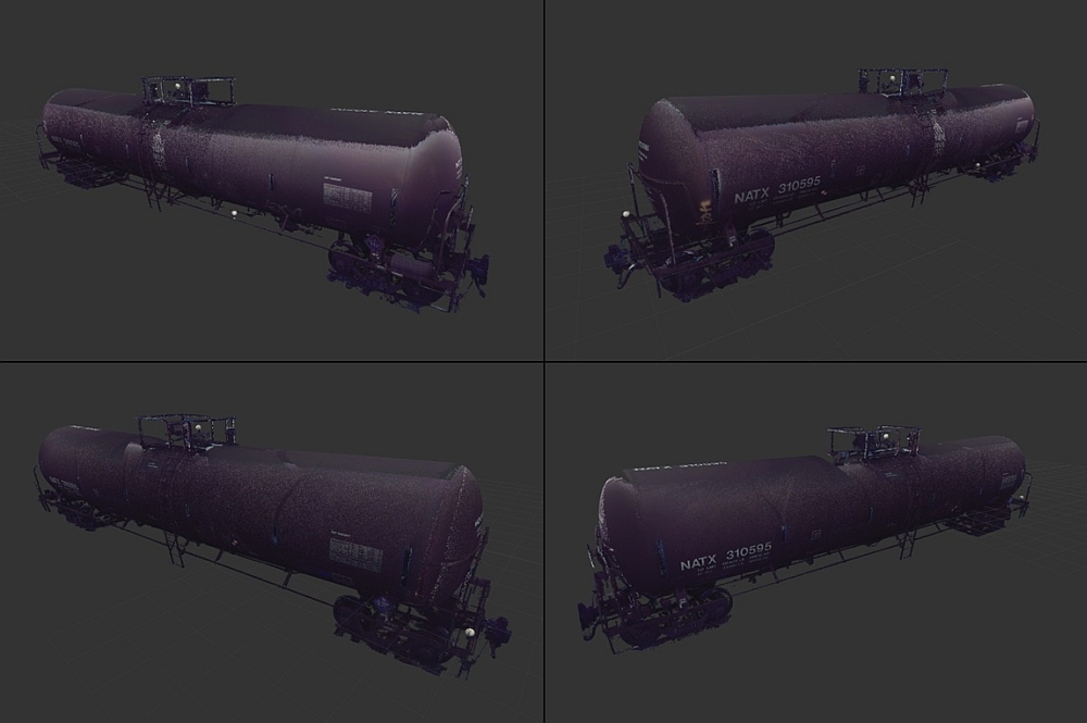
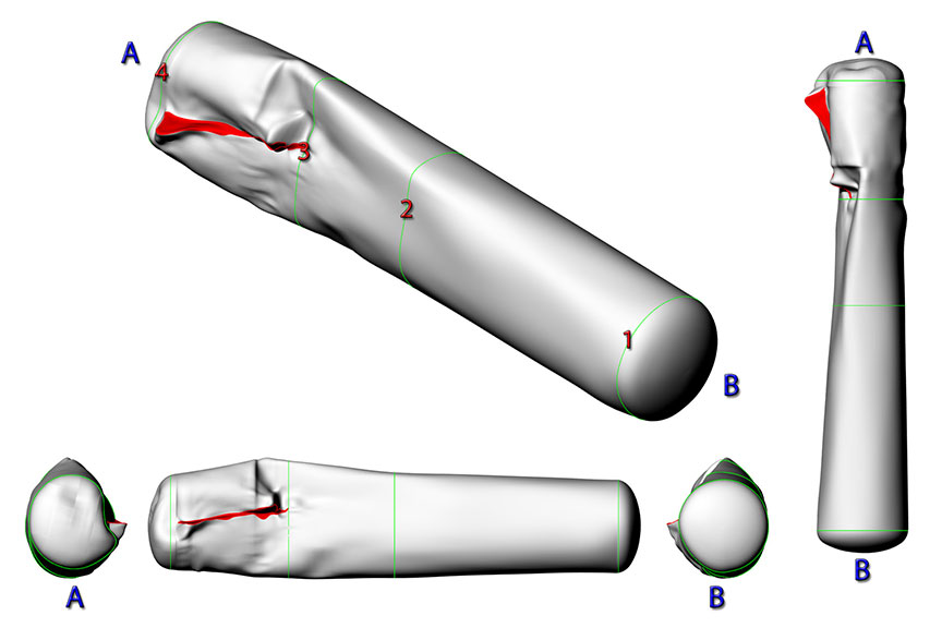
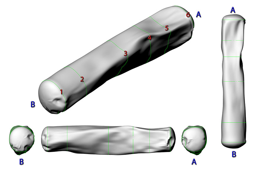
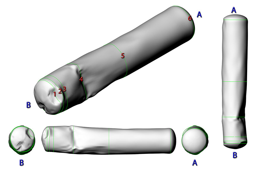
A laser scan was conducted on an exemplar tank car (NATX 310595). The purpose of this scan was to provide a comparison of the scanned data for the damaged tank cars to the scanned data of an undamaged tank car. This provided an error analysis model when comparing the scanned data of each car to their respective comparison cars. The visualization of the exemplar tank car laser scan is shown in Figure 1.
2.2
Eight damaged tank cars were separated from the derailment site for 3D laser scanning. The tank car’s field no., consist no. and reporting marks are listed in Table 1.
| Field no.Footnote 1 | Consist no. | Reporting mark |
|---|---|---|
| 2 | 4 | WFIX 130608 |
| 10 | 12 | TILX 316570 |
| 24 | 25 | ACFX 76605 |
| 29 | 35 | WFIX 130545 |
| 36 | 38 | ACFX 71505 |
| 40 | 42 | CTCX 735572 |
| 42 | 44 | WFIX 130664 |
| 54 | 61 | TILX 316533 |
2.3
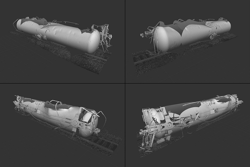
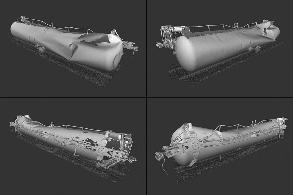
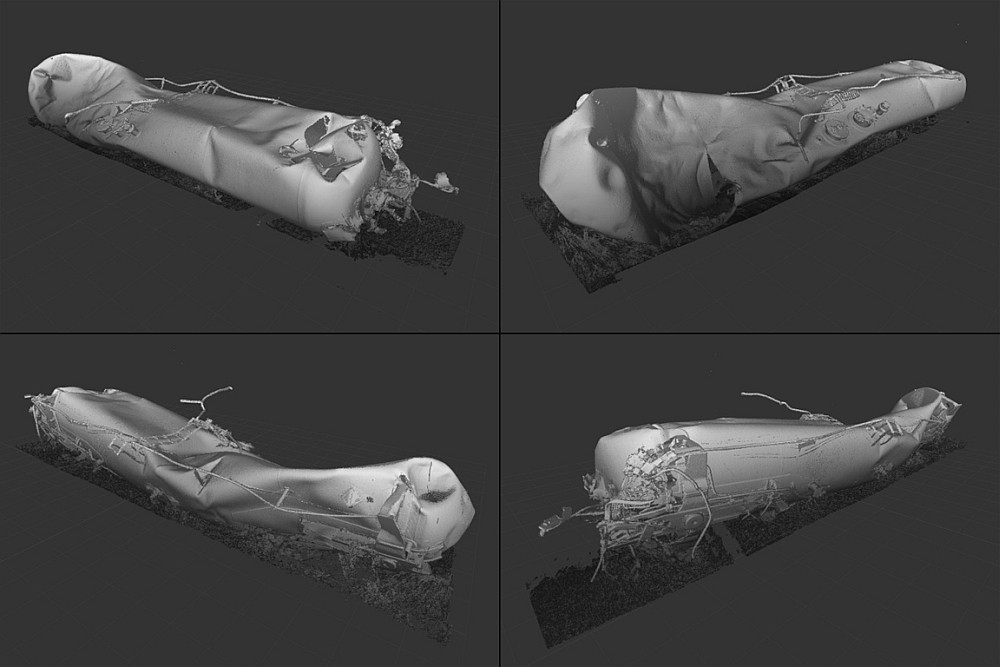
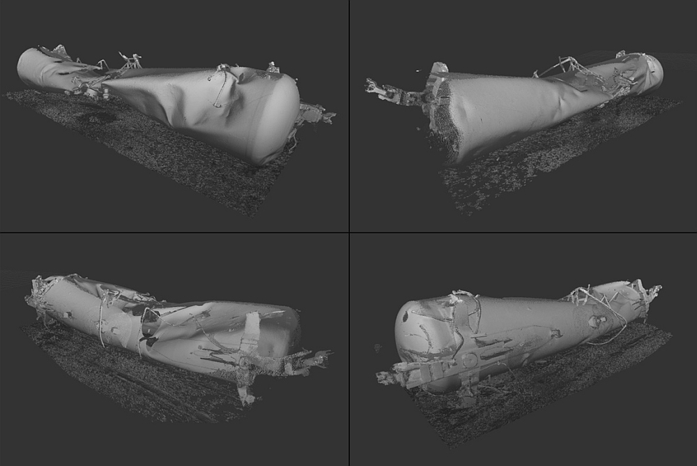
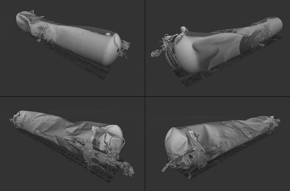
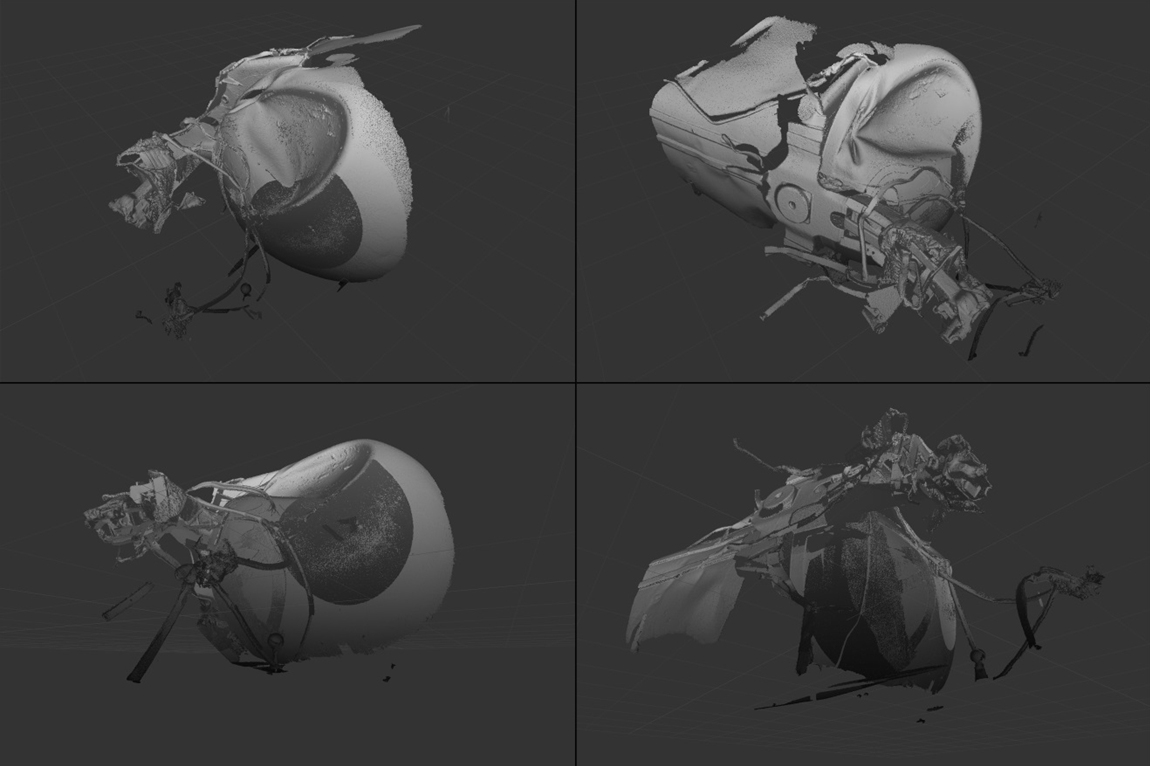
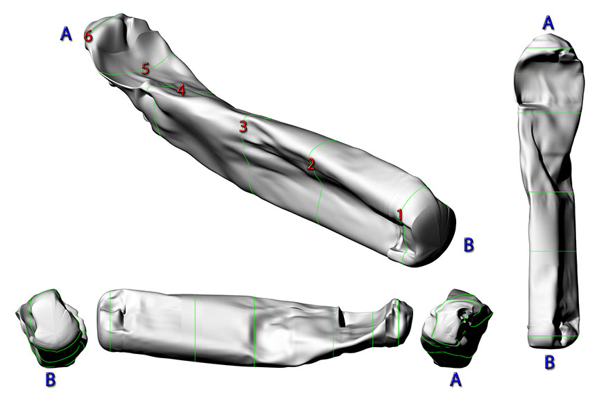
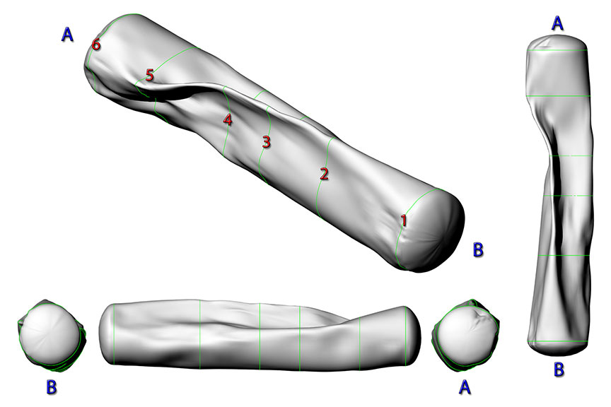
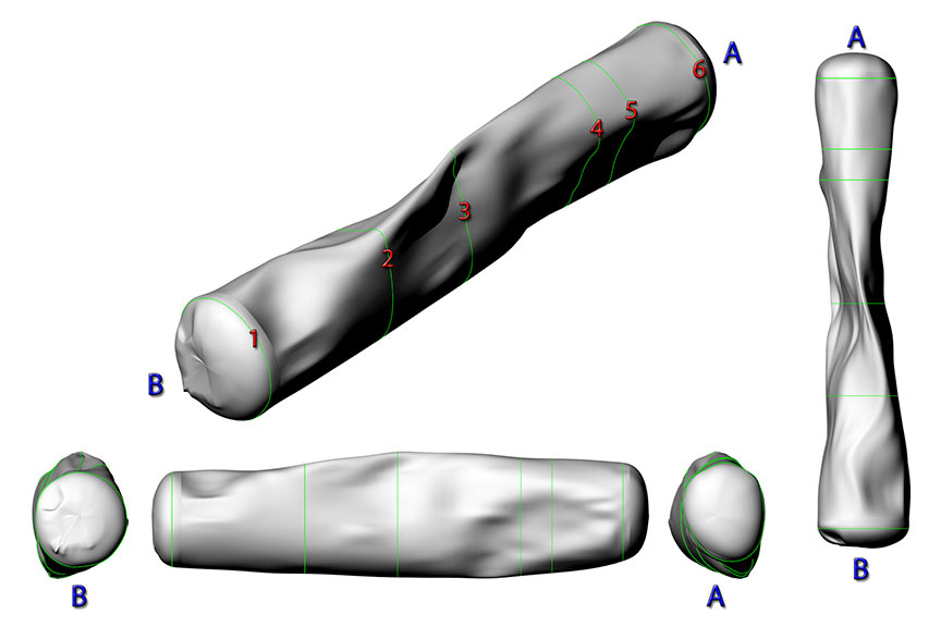
The basis for the tank car selection was the type of damage observed such as volume changes due to impact damage, dimensions of ruptures and punctures in the tank car heads and shells, and size and volume of large dents in the tank car heads. The data was also used for greyscale visualization of the tank car deformations as shown in Figures 2 through 9.
2.4
The tank cars were scanned with a FARO Laser Scanner Focus3DFootnote 2. Prior to the occurrence, the scanner was last calibrated on 12 February 2013.
2.5
Laser scanning produced point cloud data with millions of 3D points in color providing a digital reproduction of the tank car as it appeared during the examination. The FARO scanner collected the point cloud data and stored the data files in the raw format used by the data acquisition software. An entire scan of a tank car ranged from six to 29 scanner positions around each tank car depending on the damage and areas of interest on each car. Each scan position would generate a file with a file size in the order of 100 megabytes for each file. The total point cloud for each tank car ranged from 10 to 30 million points.
2.6
The registered scan files from the FARO scanner were imported into Autodesk’s ReCap software for processing, cleaning, and visualizing the large data sets. The point cloud data was exported from ReCap into a format compatible with the 3D Computer-Aided Design (CAD) software Rhinoceros. Within Rhinoceros a polygon mesh was generated from the point cloud data in order to make cross-sections for the surfaces used to measure the volume of each tank car and quantify the deformation of the tank cars.
2.7
The volumes of the undamaged tank cars used for comparison were calculated using dimensions taken from the Association of American Railroads (AAR) Certificate of Construction (COC) and manufacturer’s drawings. Dimensions used were the thickness of the shell and head material, tank length, tank bottom slope, tank inside diameter, and head radius.
3.0 Analysis
3.1 Exemplar tank car NATX 310595
3.1.1
A laser scan was conducted on an exemplar tank car (NATX 310595).Footnote 3 The purpose of this scan was to provide an estimate of the accuracy of the laser scanned data by comparing the data obtained on an undamaged car to the dimensions indicated on its COC. Detailed information about the analysis of the exemplar tank car is presented in Appendix A.
3.1.2
The volume of the tank car calculated using the scanned data was 0.6% higher than the volume of the COC L114001 tank car.
3.1.3
The tank car length calculated using the scanned data was 0.03% higher than the length of the COC L114001 tank car.
3.2
Based on the above, it is considered that the error associated with the scanned data is small in comparison to the large dimensional changes measured on the derailed tank cars.
3.3
Detailed information about the analysis of each tank car is presented in Appendix B. The following paragraphs summarize the salient results for each tank car.
3.4 Tank car WFIX 130608
3.4.1
This tank car exhibited minor dents on the tank shell with little change in the length of the shell. There was a rupture due to a thermal tear on the right sideFootnote 4 near the A end that resulted in the expansion of the shell in this area.
3.4.2
From the B end to where the rupture started there was slight deformation in the shell with minor increases in the cross-sectional area.
3.4.3
Analysis of the tank car volume could only be performed from the B end to the start of the shell rupture. The rupture resulted in a deformed expansion of the shell so the cross-sections in this area are not representative of the actual volume of the tank car prior to the rupture. The volume in this portion of the tank car increased by 1.50% as compared to the volume of an undamaged COC L116012A tank car.
3.4.4
There was a reduction of 0.29% in the length of the tank car as compared to the length of the comparison tank car.
3.4.5
The length of the rupture was approximately 4.4 m and the surface area across the rupture was measured to be approximately 2.5 m2.
3.5 Tank car TILX 316570
3.5.1
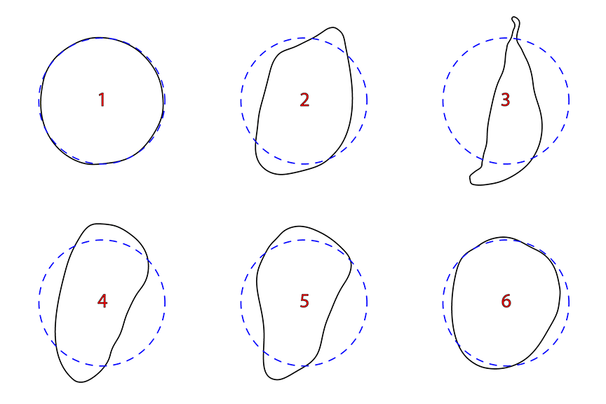
This tank car contained a large rupture on the left side near the A end resulting in the expansion of the shell in this area. Moving from the B end towards the A end, the tank car was compressed on the left side towards the center. The compression increased the vertical dimension of the tank reaching a maximum at the point where the rupture began at approximately 3.5 m from the center of the tank.
3.5.2
Analysis of the tank car volume could only be performed up until the start of the rupture. The rupture resulted in a deformed expansion of the shell so the cross-sections in this area are not representative of the actual volume of the tank car prior to the rupture. The volume in this portion of the tank car decreased by 5.52% as compared to the volume of an undamaged COC L116012A tank car.
3.5.3
There was a reduction of 0.77% in the length of the tank car as compared to the length of the comparison tank car.
3.5.4
The length of the rupture was approximately 3.9 m and the surface area across the rupture was measured to be approximately 1.1 m2.
3.6 Tank car ACFX 76605
3.6.1
This tank car exhibited extensive deformation and compression of the shell and heads. There was a large puncture in both heads, a transverse rupture in the shell, and several other shell breaches.
3.6.2
The volume of the tank car decreased by 39.7% as compared to the volume of an undamaged COC A841016 tank car.
3.6.3
There was a reduction of 2.76% in the length of the tank car as compared to the length of the comparison tank car.
3.6.4
The cross-sections of ACFX 76605 exhibited nearly a three-quarter reduction in area at about 1 metre from the A end of the tank car. The compression of the shell reduced the volume by more than one-third of the volume of the comparison tank car.
3.7 Tank car WFIX 130545
3.7.1
This tank car was compressed on the left and right sides of the tank car. This compression pinched the shell together near the top of the tank car. There were no punctures in the heads or shell.
3.7.2
The volume of the tank car decreased by 26.8% as compared to the volume of an undamaged COC L116012A tank car.
3.7.3
There was a reduction of 1.58% in the length of the tank car as compared to the length of the comparison tank car.
3.7.4
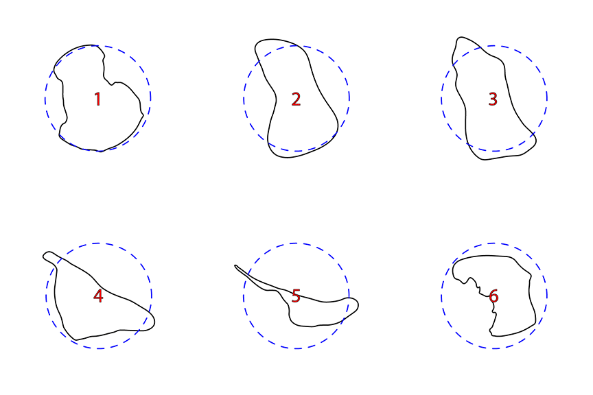
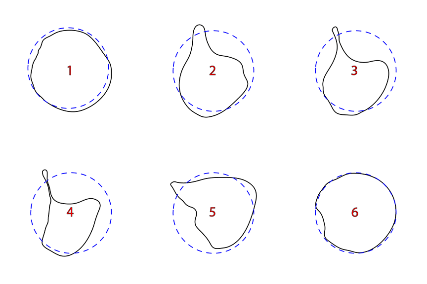
The more deformed portions of the shell (for example see cross-sections 3 and 4 in Figure B-12) exhibited a significant decrease of the radius of curvature. The radius of curvature at the top of the buckle in the centre of the tank car and 2 m towards the A end are 0.10 m and 0.09 m respectively. The radius of curvature for the cross-section of the comparison tank car is 1.524 m.
3.7.5
There was a significant change in volume of WFIX 130545 due to the localized deformation. The cross-sections exhibited nearly a one-half reduction in area at about 2 m from the centre of the tank car towards the A end. The compression of the shell reduced the volume by almost one-third of the volume of the comparison tank car.
3.8 Tank car ACFX 71505
3.8.1
The A end of ACFX 71505 was not laser scanned in detail due to time limitations. More information is provided in Appendix B-5.0 on this tank car reconstruction.
3.8.2
This tank car was compressed on the left and right sides near the center of the tank. The shell had a rupture near the B end. Both heads were dented with a small puncture in the B end.
3.8.3
The volume of the tank car decreased by 22.8% as compared to the volume of an undamaged COC A811019A tank car.
3.8.4
There was a reduction of 2.42% in the length of the tank car as compared to the length of the comparison tank car.
3.9 Tank car CTCX 735572
3.9.1
The shell of this tank car was compressed on three sides (left, right, and top) resulting in a wedge shape near the center. There were dents on both the A and B ends of the tank car.
3.9.2
The volume of the tank car decreased by 11.2% as compared to the volume of an undamaged COC L121031C tank car.
3.9.3
There was a reduction of 0.60% in the length of the tank car as compared to the length of the comparison tank car.
3.10 Tank car WFIX 130664
3.10.1
Only the A end of this tank car was laser scanned with emphasis on a dent on the head of the tank and a separation at the fillet weld between the front sill pad and head
3.10.2
The measured volume of the dent was approximately 0.64 m3 (169 US gallons) as compared to the surface of the undamaged COC tank car. The surface area of the dent was approximately 2.8 m2 (30 ft2).
3.10.3
The stub sill had separated at the fillet weld between the front sill pad and the head. This crack had propagated to the body bolster pad fillet weld and into the head-to-shell weld. The lower crack was 0.50 m in length with a maximum width of 0.11 m. The upper crack was 0.25 m in length with a maximum width of 0.03 m.
3.10.4
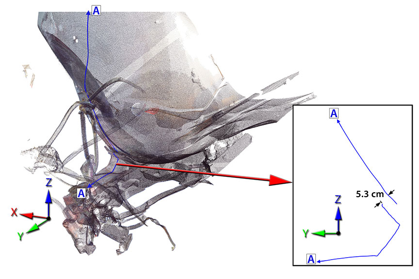
Along the centerline of the tank car the gap between the front sill pad and the head was measured to be approximately 5.3 cm. The separation of the front sill pad was greater along the top edge and became smaller as it approached the lower portion of the front sill pad closer to the stub sill.
3.11 Tank car TILX 316533
3.11.1
This tank car had minor deformations in the shell moving from the A end towards the B end until the centre of the tank car. There were no breaches in the tank.
3.11.2
About 4.3 m from the center of the tank car towards the B end of the tank car the shell was compressed on the right side with dents and deformations on the other sides of the shell. There was an 11.5% reduction of the cross-sectional area of the shell and two large dents on the B end of the tank car.
3.11.3
The volume of the tank car decreased by 2.7% as compared to the volume of an undamaged COC L116012A tank car.
3.11.4
There was a reduction of 0.51% in the length of the tank car as compared to the length of the comparison tank car.
4.0 Conclusion
4.1
The errors associated with length and volume measurements derived from the 3D laser scan data were small in comparison with the significant length and volume changes measured on the subject cars.
4.2
Analysis of the 3D laser scan data for car WFIX 130608 indicated that the thermal tear was 4.4 m in length, with a surface area of about 2.5 m2. The length of this car was reduced by about 0.29% as compared to an undamaged car. The portion of the tank located away from the thermal tear exhibited a small volume increase of about 1.5% relative to an undamaged car.
4.3
Analysis of the 3D laser scan data for car TILX 316570 indicated that the rupture in the shell was 3.9 m in length, with a surface area of about 1.1 m2. The length of this car was reduced by about 0.77% as compared to an undamaged car. The portion of the tank located away from the rupture exhibited a reduction in volume of approximately 5.52% relative to an undamaged car. The cross sectional area adjacent to the rupture had decreased by about 17% relative to an undamaged car.
4.4
Analysis of the 3D laser scan data for the 4 cars with extensive impact deformation (ACFX 76605, WFIX 130545, ACFX 71505 and CTCX 735572) revealed volume reductions ranging from 11% (CTCX 735572) to close to 40% (ACFX 76605) relative to an undamaged car.
4.5
Measurement of cross-sectional changes in the most deformed portions of the shells showed cross-sectional area reductions of up to 75%. The radius of curvature measured at a sharp buckle in the shell of car WFIX 130545 was about 0.1 m; the radius of curvature of the undamaged COC L116012A shell is 1.52 m.
4.6
The length reduction relative to an undamaged car ranged from 0.6% for the least deformed car (CTCX 735572) to 2.76% for the most deformed car (ACFX 76605).
4.7
Analysis of the 3D laser scan data for car WFIX 130664 indicated that the lower tank breach was 0.50 m long and 0.11 m wide. The upper tank breach was 0.25 m long and 0.03 m wide. The gap between the separated front sill pad and the head surface was about 5.3 cm. A dent located in the head adjacent to the front sill pad separation had a volume of about 0.64 m3 and a surface area of about 2.8 m2.
4.8
Analysis of the 3D laser scan data indicated that the transverse buckle on the right side of car TILX 316533 was associated with an 11.5% reduction of the tank cross-sectional area, a 2.7% volume reduction and a 0.51% decrease in length.
Appendices
Appendix A: Exemplar laser scan for error analysis model
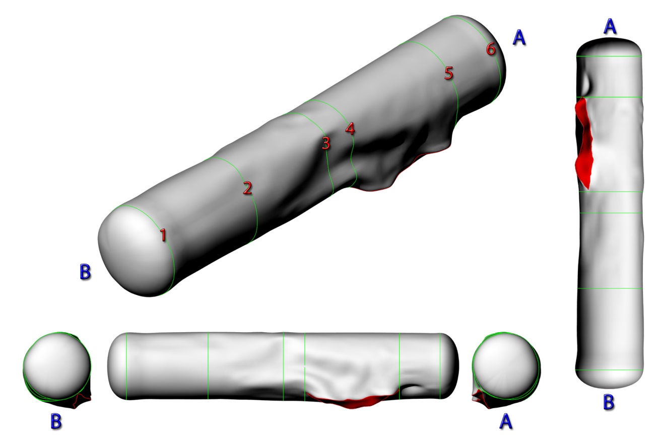
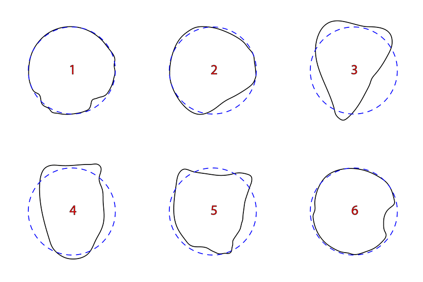
A laser scan was conducted on an exemplar tank car (NATX 310595). The purpose of this scan was to provide a comparison of the scanned data for the damaged tank cars to the scanned data of an undamaged tank car. This provided an error analysis model when comparing the scanned data of each car to their respective comparison cars.
A 3D CAD model was built for comparison to the NATX 310595 tank car using dimensions from the Greenbrier Manufacturing Operations Tank Arrangement drawing A13313 as per COC L114001. The dimensions necessary to construct the 3D CAD model were the tank length: 16.448 m (53'-11 9/16"), tank slope: 1.194 degrees, 2:1 ellipsoidal head, and outside diameter: 3.048 m (10'-0").
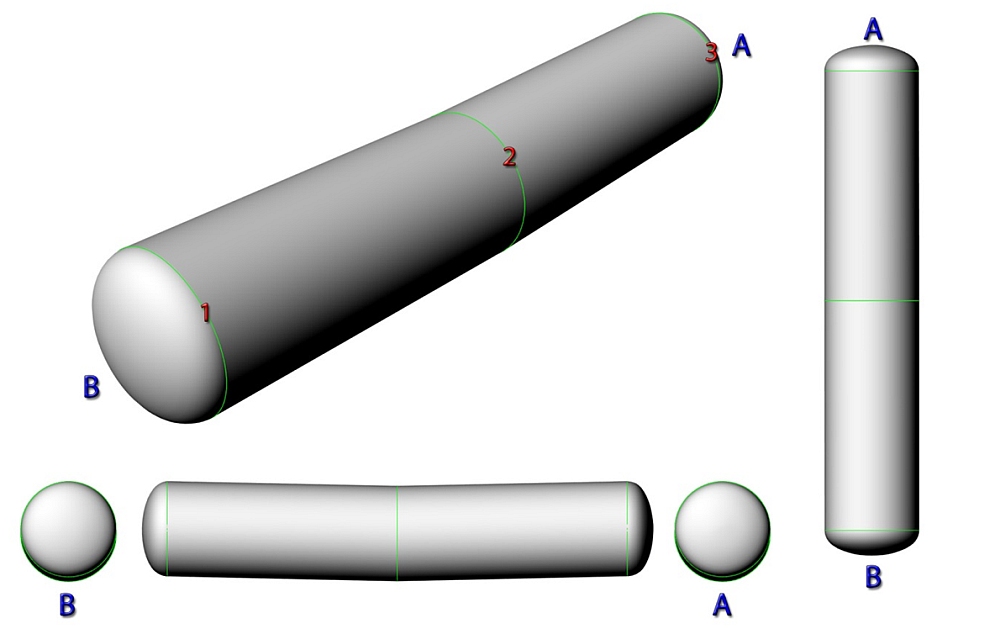
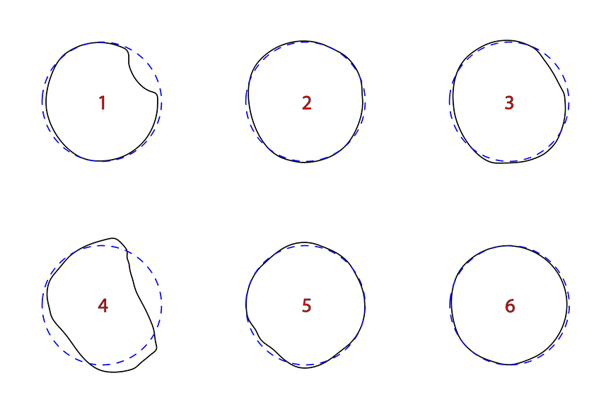
A 3D model of NATX 310595 was constructed from the laser scan data to measure cross-sections and volume. Since there was no impact deformation, cross-sections on each end and at the centre of the tank car were used for comparison against the cross-section of the comparison tank car COC L114001. Figures A-1 and A-2 show the 3D model views of NATX 310595 and the cross-sections.
Only the exterior of all the tank cars were scanned for the volume comparison analysis. The volume estimates were based only on the exterior dimensions. The difference in volume as due to the thickness of the tank shell and heads was small as compared to the entire volume of the tank cars,
| Cross-Section | Location (m) | Area (m2) | COC L114001 Area (m2) | Δ Area (m2) | % Difference |
|---|---|---|---|---|---|
| 1 | +7.4 | 7.33 | 7.30 | +0.03 | +0.4 |
| 2 | 0 | 7.38 | 7.30 | +0.08 | +1.1 |
| 3 | -7.4 | 7.31 | 7.30 | +0.01 | +0.1 |
Table A-1 shows the measurements for NATX 310595 tank car as compared to the comparison undamaged COC L114001 tank car.
As there was no shell rupture to deform the shell of this tank car the change in volume can be represented by comparing the volume from the comparison car to the volume of the tank car for the entire tank car shell.
- Volume of NATX 310595 section: 117.03 m3
- Volume of COC L114001 section: 116.32 m3
- Δ Volume in section: +0.71 m3
- % Difference: +0.6%
There was a negligible increase in length of NATX 310595 as compared to the length of the comparison tank car.
- Length of NATX 310595: 16.45 m (53'-11 3/4")
- Length of COC L114001: 16.45 m (53'-11 9/16")
- Δ Length: +0.01 m (3/16")
- % Difference: +0.03%
The error on the volume measurements of the exemplar tank car was small relative to the volume changes observed and measured on the damaged tank cars.
Appendix B: Tank car dimensional analysis results
B-1.0 WFIX 130608
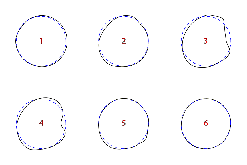
| Cross-Section | Location (m)Footnote 5 | Area (m2) | COC L116012A Area (m2) | Δ Area (m2) | % Difference |
|---|---|---|---|---|---|
| 1 | +7.3 | 7.70 | 7.33 | +0.37 | +5.0 |
| 2 | +3.5 | 7.41 | 7.33 | +0.08 | +1.1 |
| 3 | 0 | 7.23 | 7.33 | -0.10 | -1.4 |
| 4 | -1 | 7.45 | 7.33 | +0.12 | +1.6 |
| 5 | -5.4 | 7.63 | 7.33 | +0.30 | +4.1 |
| 6 | -7.3 | 7.36 | 7.33 | +0.03 | +0.4 |
Multiple cross-sections were taken along each tank car scan where deformation occurred to produce the surface for volume analysis. The cross-sections used in Appendix B were used to display only the significant deformations.
The Δ Area is the calculated change in cross-sectional area from that of the comparison undamaged COC L116012A tank car to the cross-sectional area of the surface defined by the laser scanned point cloud data for WFIX 130608. The % Difference is the percentage difference between the two cross-sections calculated by dividing the Δ Area by the cross-sectional area of the comparison car.
The volume of WFIX 130608 could not be calculated over the entire surface constructed from the laser scanned point cloud due to the shell rupture at the A end of the tank car. The shell rupture resulted in a deformed expansion of the shell along the length of the rupture so the cross-sections in this area are not representative of the actual volume of the tank car prior to the rupture.
The change in volume can be represented by comparing the volume of the surface measured from the B end of the tank car to the cross-section at the -1 m location along the length of the tank car for both the comparison car and the laser scanned car. The percentage difference in the volume of this subsection of the tank car is representative of the percentage difference in volume across the entire tank car.
- Volume of WFIX 130608 section: 66.49 m3
- Volume of COC L116012A section: 65.51 m3
- Δ Volume in section: +0.98 m3
- % Difference: +1.50%
There was only a minor reduction in length of WFIX 130608 as compared to the length of the undamaged tank car.
- Length of WFIX 130608: 16.36m (53'-7 31/32")
- Length of COC L116012A: 16.40 m (53'-9 13/16")
- Δ Length: -0.05 m (1 27/32")
- % Difference: -0.29%
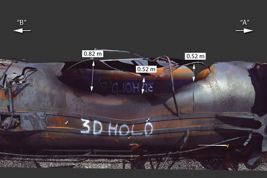
The portion of the tank car near the A end had to be discounted when measuring the volume (refer to Figure B-3). After the tank ruptured the deformation would have created a gap across the cross-section in this region, thus affecting the volume.
The separation in the rupture increased when moving from it’s A end extremity towards the middle. Up until half way along the rupture the separation distance was measured to be 0.52 m with some fluctuations and extended to as much as 0.82 m approaching the B end extremity. The length of the rupture was approximately 4.4 m and the surface area across the rupture was measured to be approximately 2.5 m2.
B-2.0 TILX 316570
| Cross-Section | Location (m) | Area (m2) | COC L116012A Area (m2) | Δ Area (m2) | % Difference |
|---|---|---|---|---|---|
| 1 | +7.4 | 7.16 | 7.33 | -0.17 | -2.3 |
| 2 | 0 | 6.77 | 7.33 | -0.56 | -7.6 |
| 3 | -3.5 | 6.07 | 7.33 | -1.26 | -17.2 |
| 4 | -7.4 | 6.82 | 7.33 | -0.51 | -7.0 |
Table B-2 shows the measurements for TILX 316570 tank car as compared to the comparison undamaged COC L116012A tank car.
The volume of TILX 316570 could not be calculated over the entire surface constructed from the laser scanned point cloud due to the shell rupture at the A end of the tank car. The rupture resulted in a deformed expansion of the shell so the cross-sections in this area are representative of the present state of the tank car and not the actual volume of the tank car prior to the rupture.
The change in volume can be represented by comparing the volume of the surface measured from the B end of the tank car to the cross-section at the -3.5 m location along the length of the tank car for both the comparison car and the laser scanned car. The percentage difference in the volume of this subsection of the tank car is representative of the percentage difference in volume for the entire tank car since the deformation along the entire tank car would behave in a similar fashion.
- Volume of TILX 316570 section: 79.24 m3
- Volume of COC L116012A section: 83.88 m3
- Δ Volume in section: -4.63 m3
- % Difference: -5.52%
There was only a minor reduction in length of TILX 316570 as compared to the length of the undamaged tank car.
- Length of TILX 316570: 16.28 m (53'-4 13/16")
- Length of COC L116012A: 16.40 m (53'-9 13/16")
- Δ Length: -0.13 m (5")
- % Difference: -0.77%
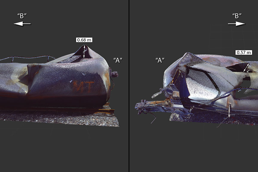
The rupture on the left side of the tank car near the “A” end had to be discounted when measuring the volume in this region of the tank car (refer to Figure B-6). After the tank ruptured, the deformation would have created a gap across the cross-section in this region thus affecting the volume in this region.
There was a decrease in the tank car volume moving from the B end towards the A end. A rupture started at approximately 3.5 m from the center of the tank car moving towards the A end of the shell. The upper portion of the rupture extends beyond the deformation by 0.68 m and then switches to the lower portion that extends by 0.57 m approaching the B end. There is a buckle in the top portion of the tank that extended upward due to the compression in the left side of the tank. Following the rupture the cross-section of the tank returns to the original shape near the B end of the tank. The length of the rupture was approximately 3.9 m and the surface area across the rupture was measured to be approximately 1.1 m2.
B-3.0 ACFX 76605
| Cross-Section | Location (m) | Area (m2) | COC A841016 Area (m2) | Δ Area (m2) | % Difference |
|---|---|---|---|---|---|
| 1 | +7.0 | 5.02 | 7.30 | -2.28 | -31.2 |
| 2 | +3.0 | 5.09 | 7.30 | -2.21 | -30.3 |
| 3 | 0 | 4.93 | 7.30 | -2.37 | -32.5 |
| 4 | -4.0 | 4.06 | 7.30 | -3.24 | -44.4 |
| 5 | -6.0 | 1.93 | 7.30 | -5.37 | -73.6 |
| 6 | -7.25 | 3.52 | 7.30 | -3.78 | -51.8 |
Table B-3 shows the measurements for ACFX 76605 tank car as compared to the comparison undamaged COC A841016 tank car.
As there was a minor shell rupture, which did not deform the surrounding tank car shell, the change in volume can be represented by comparing the volume from the comparison car to the volume of the tank car for the entire tank car shell.
- Volume of ACFX 76605: 69.76 m3
- Volume of COC A841016: 115.71 m3
- Δ Volume in section: -45.95 m3
- % Difference: -39.7%
There was a reduction in length of ACFX 76605 as compared to the length of the undamaged tank car.
- Length of ACFX 76605: 15.97 m (52'-4 21/32")
- Length of COC A841016: 16.42 m (53'-10 1/2")
- Δ Length: -0.45 m (1'-5 27/32")
- % Difference: -2.76%
The cross-sections of ACFX 76605 exhibited nearly a three-quarter reduction in area at about 1 metre from the A end of the tank car. The compression of the shell reduced the volume by more than one-third of the volume of the undamaged tank car.
B-4.0 WFIX 130545
| Cross-Section | Location (m) | Area (m2) | COC L116012A Area (m2) | Δ Area (m2) | % Difference |
|---|---|---|---|---|---|
| 1 | +7.3 | 7.16 | 7.33 | -0.17 | -2.3 |
| 2 | +3.0 | 5.38 | 7.33 | -1.95 | -26.6 |
| 3 | 0 | 4.41 | 7.33 | -2.92 | -39.8 |
| 4 | -2.0 | 3.46 | 7.33 | -3.87 | -52.8 |
| 5 | -5.0 | 5.62 | 7.33 | -1.71 | -23.3 |
| 6 | -7.3 | 6.93 | 7.33 | -0.40 | -5.5 |
Table B-4 shows the measurements for WFIX 130545 tank car as compared to the comparison undamaged COC L116012A tank car.
As there was no shell rupture to deform the shell of this tank car the change in volume can be represented by comparing the volume from the comparison car to the volume of the tank car for the entire tank car shell.
- Volume of WFIX 130545: 85.21 m3
- Volume of COC L116012A: 116.43 m3
- Δ Volume in section: -31.22 m3
- % Difference: -26.8%
There was only a minor reduction in length of WFIX 130545 as compared to the length of the comparison tank car.
- Length of WFIX 130545: 16.14 m (52'-11 9/16")
- Length of COC L116012A: 16.40 m (53'-9 13/16")
- Δ Length: -0.26 m (10 1/4")
- % Difference: -1.58%
The radius of curvature measured at the tip of the sharp buckle in cross-sections 3 and 4 (at the centre of the tank car and 2 m towards the A end) was 0.10 m and 0.09 m respectively; the radius of curvature for the cross-section of the comparison tank car was 1.524 m.
There was a significant change in volume of WFIX 130545 due to the deformation. The cross-sections exhibited nearly a one-half reduction in area at about 2 m from the centre of the tank car towards the A end. The compression of the shell in turn reduced the volume by almost one-third of the volume of the comparison tank car.
B-5.0 ACFX 71505
The A end of ACFX 71505 was not laser scanned in detail due to time limitations. To complete the volume analysis for this tank car the A end was constructed using the curvature from the points at this end of the laser scan combined with the 2:1 ellipsoid for the COC A841016 tank head.
| Cross-Section | Location (m) | Area (m2) | COC A841016 Area (m2) | Δ Area (m2) | % Difference |
|---|---|---|---|---|---|
| 1 | +7.3 | 7.20 | 7.30 | -0.10 | -1.4 |
| 2 | +3.0 | 6.26 | 7.30 | -1.04 | -14.2 |
| 3 | 0 | 3.41 | 7.30 | -3.89 | -53.3 |
| 4 | -4.0 | 5.79 | 7.30 | -1.51 | -20.7 |
| 5 | -5.0 | 5.77 | 7.30 | -1.53 | -21.0 |
| 6 | -7.3 | 6.54 | 7.30 | -0.76 | -10.4 |
Table B-5 shows the measurements for ACFX 71505 tank car as compared to the comparison undamaged COC A841016 tank car.
As there was a minor shell rupture, which did not deform the surrounding tank car shell, the change in volume can be represented by comparing the volume from the comparison car to the volume of the tank car for the entire tank car shell.
- Volume of ACFX 71505: 89.34 m3
- Volume of COC A841016: 115.71 m3
- Δ Volume in section: -26.37 m3
- % Difference: -22.8%
There was a reduction in length of ACFX 71505 as compared to the length of the comparison tank car.
- Length of ACFX 71505: 16.02 m (52'-6 13/16")
- Length of COC A841016: 16.42 m (53'-10 1/2")
- Δ Length: -0.40 m (1'-3 11/16")
- % Difference: -2.42%
B-6.0 CTCX 735572
| Cross-Section | Location (m) | Area (m2) | COC L121031C Area (m2) | Δ Area (m2) | % Difference |
|---|---|---|---|---|---|
| 1 | +7.4 | 7.15 | 7.30 | -0.15 | -2.1 |
| 2 | +5.0 | 6.86 | 7.30 | -0.44 | -6.0 |
| 3 | 0 | 6.01 | 7.30 | -1.29 | -17.7 |
| 4 | -3.0 | 6.23 | 7.30 | -1.07 | -14.7 |
| 5 | -5.0 | 6.12 | 7.30 | -1.18 | -16.2 |
| 6 | -7.4 | 6.58 | 7.30 | -0.72 | -9.9 |
Table B-6 shows the measurements for CTCX 735572 tank car as compared to the comparison undamaged COC A841016 tank car.
As there was no shell rupture to deform the shell of this tank car the change in volume can be represented by comparing the volume from the comparison car to the volume of the tank car for the entire tank car shell.
- Volume of CTCX 735572: 102.73 m3
- Volume of COC L121031C: 115.71 m3
- Δ Volume in section: -12.98 m3
- % Difference: -11.2%
There was only a minor reduction in length of CTCX 735572 as compared to the length of the comparison tank car.
- Length of CTCX 735572: 16.32 m (53'-6 19/32")
- Length of COC L121031C: 16.42 m (53'-10 1/2")
- Δ Length: -0.10 m (3 29/32")
- % Difference: -0.60%
B-7.0 WFIX 130664
Only the A end of this tank car was laser scanned since this scan was a higher detailed scan intent on capturing the damage on this end of the tank car. The areas of interest for this end of the tank car were the dent on the head of the tank and the front sill pad failure.
On the A end of WFIX 130664 there was a large impact dent (refer to Figure B-15). To measure the volume of the dent a 3D model was built of the tank head for the undamaged COC L116012A tank car. The curvature of the point cloud data was applied to the 3D model to cut out a section representative of the impact dent. The measured volume of the dent was approximately 0.64 m3 (169 US gallons). The surface area of the dent was approximately 2.8 m2 (30 ft2).
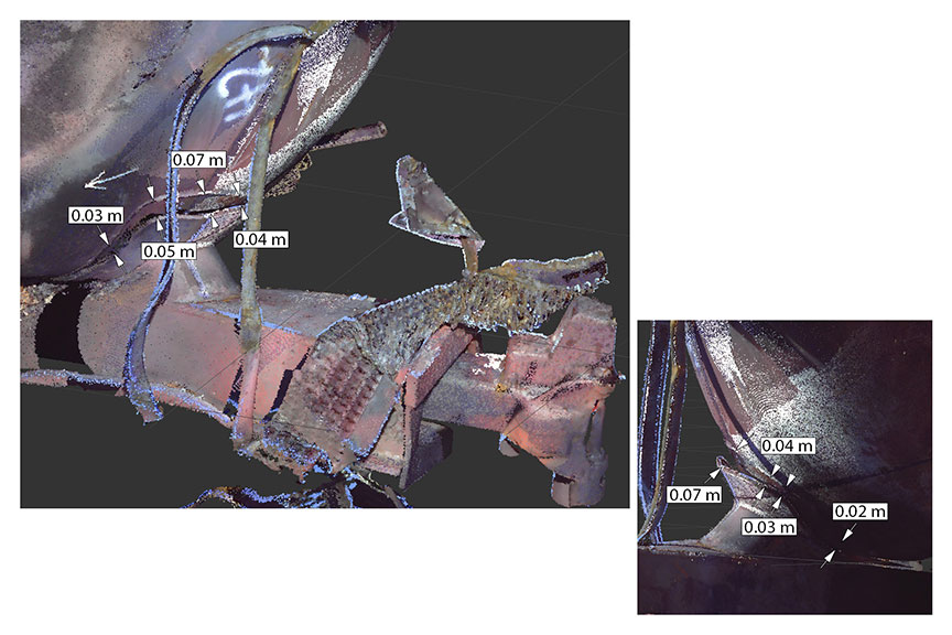
The stub sill of WFIX 130664 had separated at the fillet weld between the front sill pad and the head. This crack had propagated to the body bolster pad fillet weld and into the head-to-shell weld. The lower crack was 0.50 m in length with a maximum width of 0.11 m. The upper crack was 0.25 m in length with a maximum width of 0.03 m.
Along the centerline of the tank car the gap between the front sill pad and the head was measured to be approximately 5.3 cm (refer to Figure B-16). The separation of the front sill pad was greater along the top edge and became smaller as it approached the lower portion of the front sill pad closer to the stub sill (refer to Figure B-17).
B-8.0 TILX 316533
| Cross-Section | Location (m) | Are (m2) | COC L116012A Area (m2) | Δ Area (m2) | % Difference |
|---|---|---|---|---|---|
| 1 | +7.5 | 6.47 | 7.33 | -0.86 | -11.7 |
| 2 | +7.2 | 7.27 | 7.33 | -0.06 | -0.8 |
| 3 | +6.7 | 7.15 | 7.33 | -0.18 | -2.5 |
| 4 | +4.3 | 6.49 | 7.33 | -0.84 | -11.5 |
| 5 | 0 | 7.28 | 7.33 | -0.05 | -0.7 |
| 6 | -7.5 | 7.08 | 7.33 | -0.25 | -3.4 |
Table B-7 shows the measurements for TILX 316533 tank car as compared to the comparison undamaged COC L116012A tank car.
As there was no shell rupture to deform the shell of this tank car the change in volume can be represented by comparing the volume from the comparison car to the volume of the tank car for the entire tank car shell.
- Volume of TILX 316533: 113.23 m3
- Volume of COC L116012A: 116.43 m3
- Δ Volume in section: -3.20 m3
- % Difference: -2.7%
There was only a minor reduction in length of TILX 316533 as compared to the length of the comparison tank car.
- Length of TILX 316533: 16.32 m (53'-6 9/16")
- Length of COC L116012A: 16.40 m (53'-9 13/16")
- Δ Length: -0.08 m (3 1/4")
- % Difference: -0.51%
This lab report is part of the Transportation Safety Board of Canada's investigation report R13D0054.
