Table of contents
1.0 Introduction
1.1 Description of occurrence
1.1.1
On 06 July 2013, at approximately 0115 Eastern Daylight Time (EDT), Montreal, Maine & Atlantic (MMA) freight train MMA-02 carrying petroleum crude oil derailed in the town of Lac-Mégantic, Quebec. Numerous tank cars ruptured, lost their content and a fire ensued.
1.2 Engineering services requested
1.2.1
A request was received from the Transportation Safety Board of Canada (TSB) Eastern Regional Operations - Rail/Pipeline office to examine various components of the locomotive air brake system in order to determine the causes for identified air leaking or malfunctioning of those components.
1.3 Background
1.3.1
The occurrence train had 5 locomotives. Examination of their air brake systems revealed some deficits and associated components were retrieved for further examination and analysis.
1.4 Parts received
1.4.1
Table 1 summarizes the pertinent information for the parts received.
| Item | Description | Qty | Remarks |
|---|---|---|---|
| Main reservoir check valve | Retrieved from air brake system of locomotive unit MMA-5017 | 1 | Test indicates excessive air leakingFootnote 1 |
| Compressor relief valve | Retrieved from air brake system of locomotive unit MMA-5017 | 1 | Excessive air blowingFootnote 1a |
| Main reservoir check valve | Retrieved from air brake system of locomotive unit CEFX-3166. | 1 | Test indicates excessive air leakingFootnote 2 |
| Dead engine pressure regulating valve | Retrieved from air brake system of unit CEFX-3166 | 1 | Excessive leaking through the ventFootnote 2a |
| QRBFootnote 3 valve | Retrieved from air brake system of locomotive unit MMA-5026 | 1 | Malfunctioning - could not release the air in brake cylinderFootnote 4 |
2.0 Examination
2.1 Main reservoir check valve from locomotive unit MMA-5017
2.1.1
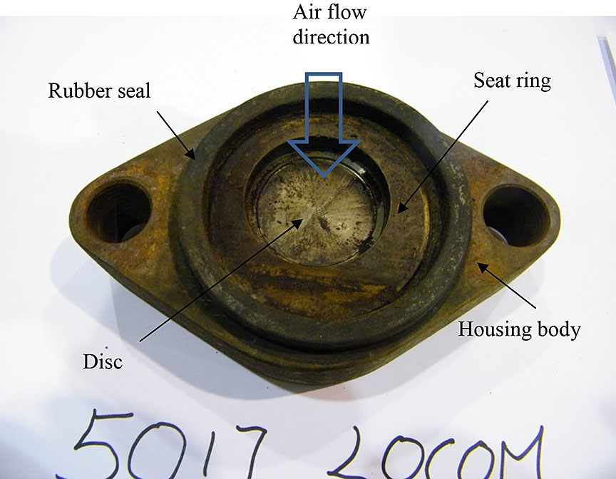
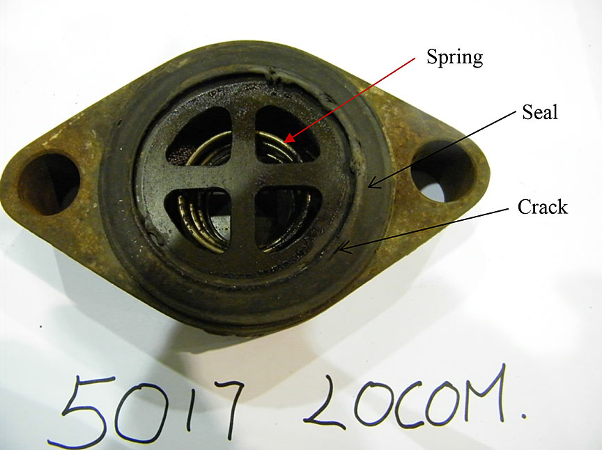
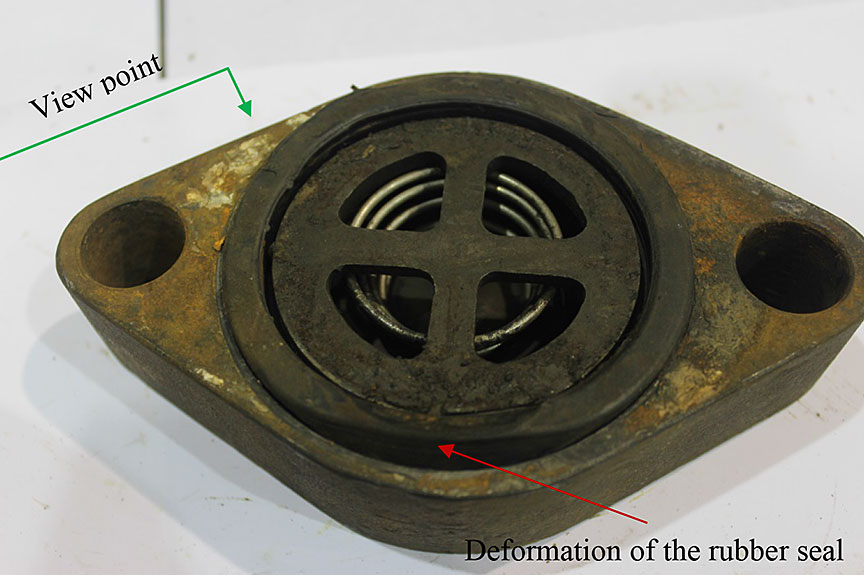
Figure 1 shows the inlet and outlet sides of the valve. The valve is a typical disc type check valve, which consists of a valve housing body, a disc, a spring, a spring retainer and a seat ring, against which the disc is pushed upon by the spring to form the valve. Viewing from the inlet side of the valve (Figure 1a), dirt accumulation is observed on the surface, which appears to be a mixture of oil and fine particles. The rubber seal has lost its elasticity and surface smoothness and is completely coated with fine particle contaminants. Viewing from the outlet side (the side connected to the main reservoir), there is visible dirt on the spring retainer and the rubber seal is badly deformed with several cracks on its edge, indicating a loss of elasticity of the seal and proper sealing function.
Figure 1. Photographs showing the main reservoir check valve from locomotive unit MMA-5017
2.1.2
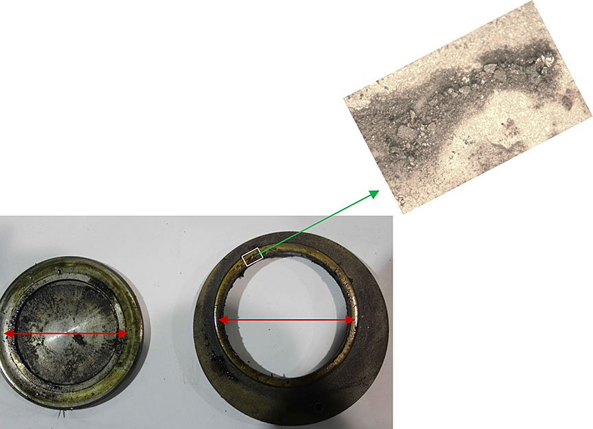
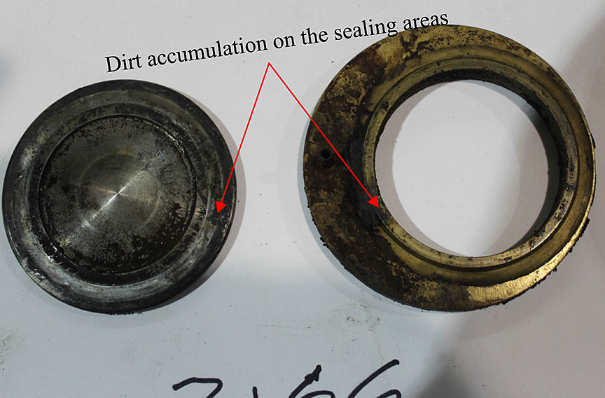
Figure 2 shows the dirt accumulation on the sealing area (which is indicated by the red arrows) of both disc and seat ring after they were taken out from the housing body. The zoomed in area in Figure 2 is an optical microscope image taken after the oil was evaporated by placing the seat ring on a laboratory hot plate for 5 minutes. The image confirms that the dirt on the sealing surface was an accumulation of fine particles, which probably contributed to air leaking of the valve.
2.1.3
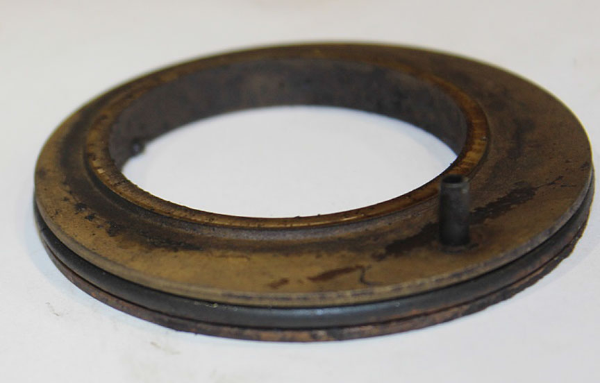
Figure 3 shows an angled view of the seat ring after it was removed from the housing body. There is an O-ring fitting into the groove on the side of the seat ring, which was designed to seal the passage between the seat ring and housing body of the check valve. The condition of this O-ring was unremarkable.
Figure 3. Angled view of seat ring with O-ring from the main reservoir check valve from locomotive unit MMA-5017
2.2 Compressor relief valve from locomotive unit MMA-5017
2.2.1
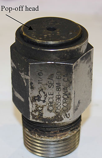
Figure 4 shows the compressor relief valveFootnote 5 (part number D559B-8M-60) that had a default setting for pop-off (or relief) pressure of 60 psi.
Figure 4. Photographs showing the compressor pressure relief valve from locomotive unit MMA-5017
2.2.2
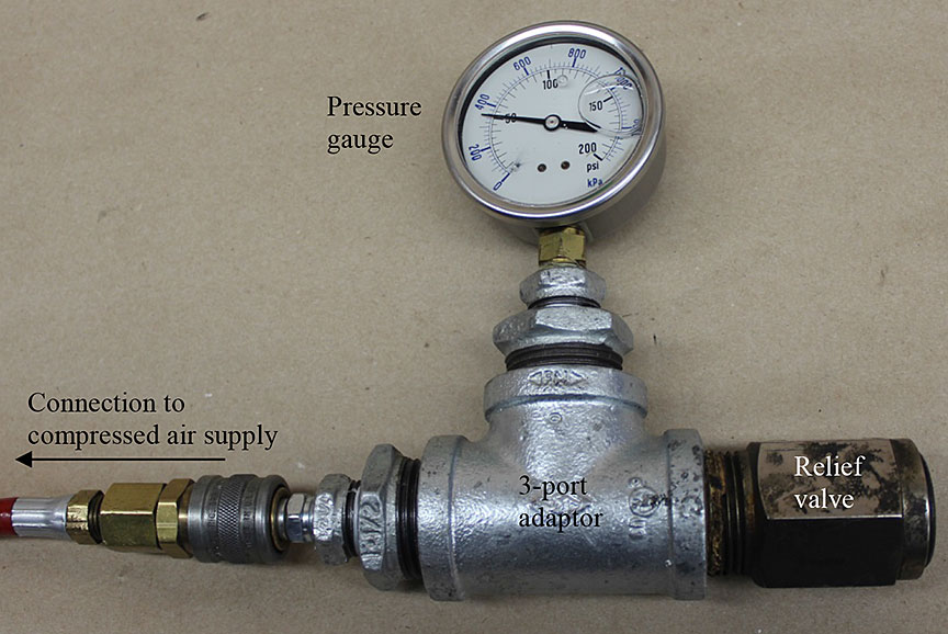
A testing setup was built to determine the pop-off pressure by connecting the valve to a 3-port adaptor with a pressure gauge mounted on one port. The remaining port of the adaptor was then connected to a compressed air supply as shown in Figure 5. The compressed air supply was equipped with a manual pressure regulator so it could be used to adjust the pressure of the air supply to the testing setup.
2.2.3
The test started at an air supply pressure of 0 psi and the pressure was slowly increased. From the very beginning, just above 0 psi, the sound of air leaking could be heard. By placing a finger in front of the head of the relief valve, a small air leak was also felt. Such leakage was detected until the test pressure reached about 50 psi when the valve was heard to pop off and the air was aggressively blown out from the valve. There was no change in the pressure gauge reading with further increase in air supply pressure. Thus the pop-off pressure of the relief valve was determined to be 50 psi whereas its default setting is 60 psi, which suggests that the relief valve’s spring may have sagged a bit over time.
2.2.4
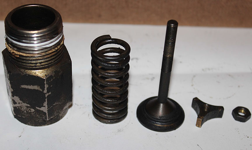
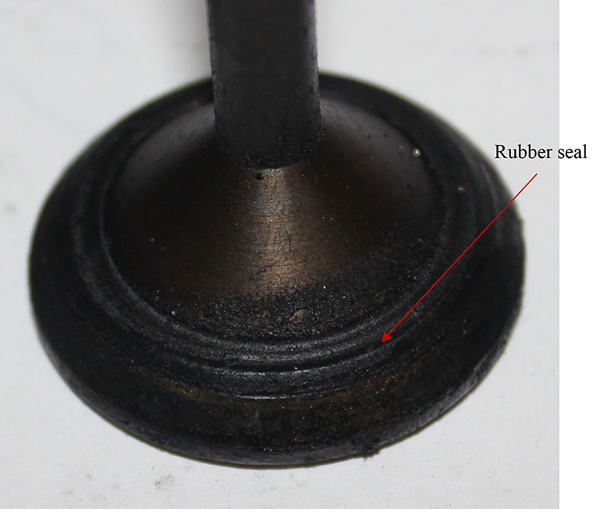
Figure 6a shows the components of the disassembled relief valve. No component was broken or visibly deteriorated except for the rubber seal on the head of the pop-off stem. This rubber seal exhibited deep grooves on its surface (Figure 6b), a sign of loss of elasticity and proper sealing function due to aging. This may explain why there was a small amount of air leaking before the relief valve activated during the test.
Figure 6. Disassembled compressor pressure relief valve from locomotive unit MMA-5017
2.3 Main reservoir check valve from locomotive unit CEFX-3166
2.3.1
Figure 7 shows the inlet and outlet (side connected to the main reservoir) sides of the check valve. This valve was of the same type as the valve from locomotive unit MMA-5017 (see section 2.1). Viewing from the inlet side of the valve (Figure 7a), dirt accumulation was observed on the valve’s internal surface. Viewing from the outlet side (Figure 7b), there was visible dirt accumulation on the spring and spring retainer. The rubber seal was badly deformed (see the red arrow on Figure 7b), indicating a loss of elasticity of the seal and its proper sealing function. When the rubber seal was taken out for further examination as shown in Figure 7c, the seal was found to be essentially broken with a large through crack along its circumferential direction.
Figure 7. Photographs showing the main reservoir check valve from locomotive unit CEFX-3166
2.3.2
Examination of the sealing surfaces on the disc and seat ring of the check valve was conducted as described in section 2.1.2. Dirt accumulation was clearly visible as indicated by the arrows in Figure 8.
2.3.3
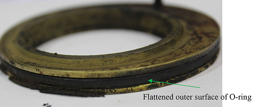
Figure 9 shows the O-ring installed on the seat ring, which is designed to seal the gap between the seat ring and housing body. The outer surface of the O-ring was flattened and it was flush with the side surface of the seat ring. This indicates that the O-ring had lost its elasticity, was permanently deformed and thus had lost its proper sealing function. The significant presence of dirt accumulation on the side wall of the seat ring is also an indication that excessive air (with dust contamination in it) had passed through the gap between the seat ring and the housing body of this check valve.
2.4 Dead engine pressure regulating valve from Locomotive Unit CEFX-3166
2.4.1
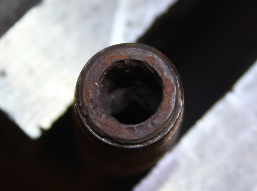
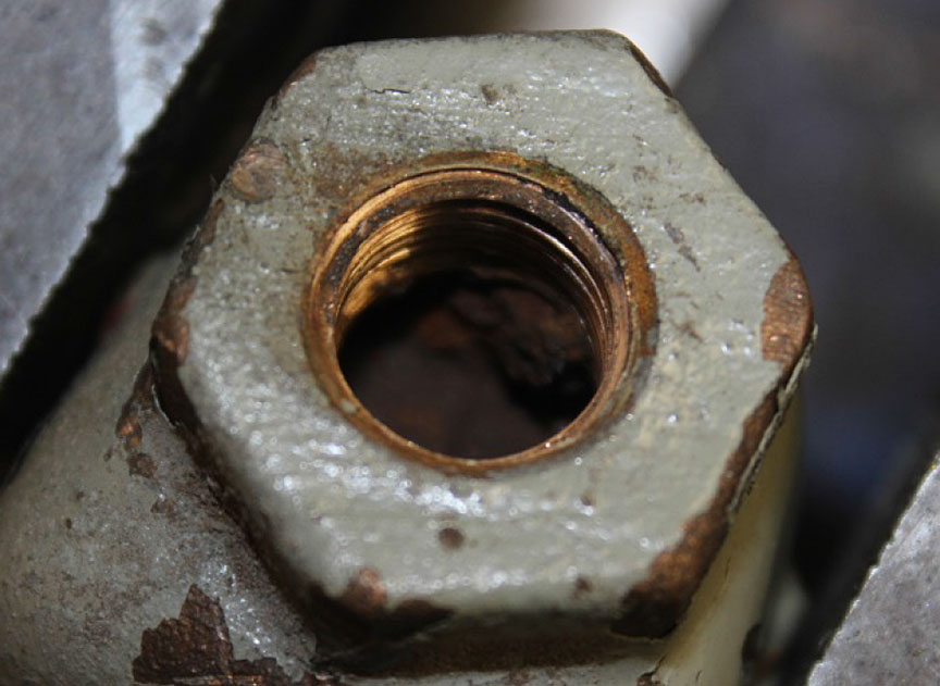
Figure 10 shows a photo of the dead engine pressure regulating valve. When examining the exit end of the outlet pipe connected to the body of the valve (marked as view point A in Figure 10), it was noted that the end of the pipe was rusted (Figure 11). Significant rust accumulation was present inside the pipe, partially blocking the outlet pipe.
2.4.2
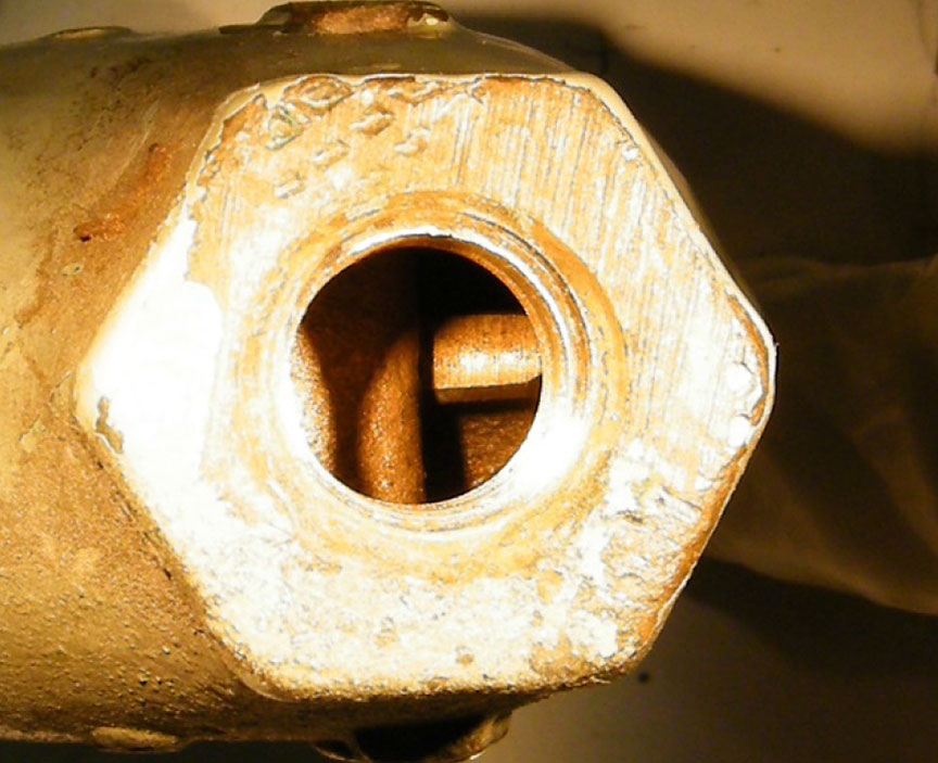
Figure 12a is a photo taken from the exit hole on the valve body (marked as view point B in Figure 10) after the outlet pipe was removed. Rust accumulation inside the valve was clearly visible. When the valve was viewed from the entrance hole after removing the inlet pipe, no rust was visible inside the valve. It was noted that the valve is made of copper. Consequently, the accumulation of rust particles on the exit side of this one-way airflow valve indicates that a reverse airflow (air leak) had occurred over a long period of time.
Figure 12. Photos showing rust accumulation inside the dead engine pressure regulating valve from locomotive unit CEFX-3166
2.4.3
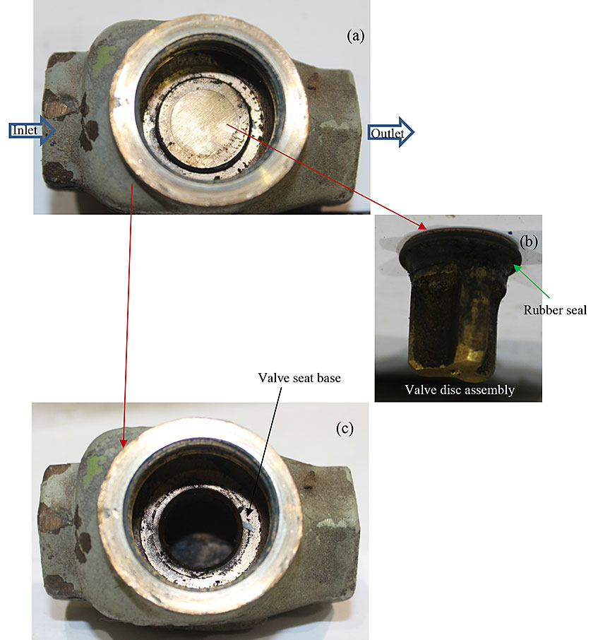
The valve cap was removed exposing the internal configuration of the valve, as shown in Figure 13. It can be seen that a disc assembly sits on the base seat to form the valve. The valve regulates the air supply to the air brake system’s reservoir such that when the outlet pressure (right side on Figure 13) is lower than the inlet pressure (left side on Figure 13), the valve opens up to increase the outlet pressure. When the inlet and outlet pressures are equal, the disc assembly returns to the base seat by gravity and the valve closes.
2.4.4
A simple test of the up and down movement of the disc assembly found that it did not move freely. When the disc assembly was raised up by blowing air from the inlet side, it did not come down freely to close the valve when the supply of air was stopped.
2.4.5
The disc assembly was removed, exposing the circular area on the base seat that is covered by the disc assembly (Figure 13c). This circular area had no visible defect except for a mixture of oil and dust particles on the surface. The disc assembly also exhibited a mixture of oil and dust particles on the rubber seal and moving guide (Figure 13b). The rubber seal contained a visible groove, an indication of aging, loss of elasticity and loss of proper sealing function. It was concluded that the sticky oil-dust mixture was likely the reason why the disc assembly did not move freely to close the valve.
2.5 QRB valve from locomotive unit MMA-5026
2.5.1
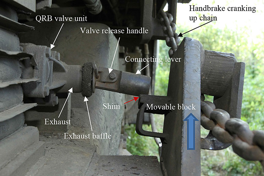
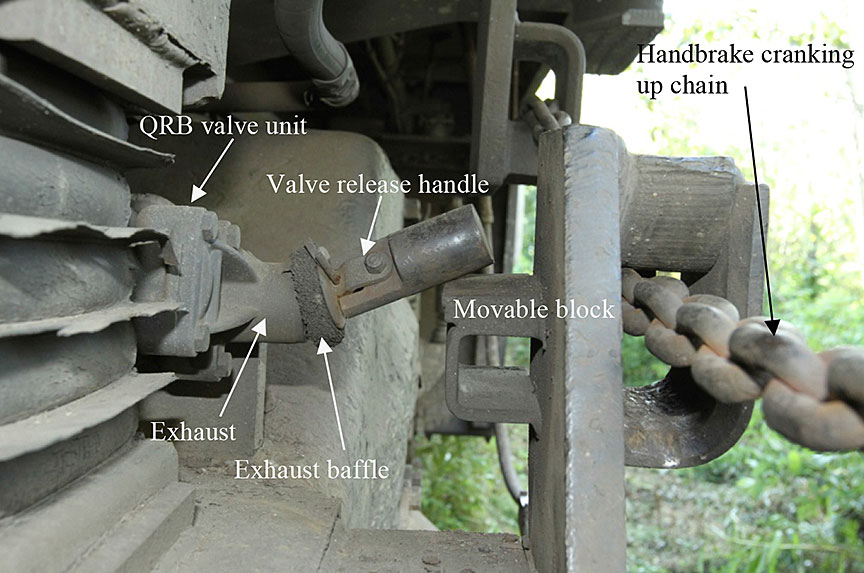
Figure 14 shows the QRB valve and its release handle’s position before and after winding up the handbrake chain. When applying the handbrake, the tensioning of the handbrake chain brings up the movable block, which in turn moves the lever connected to the handle of the QRB valve upwards, to trigger a quick release of the air in the brake cylinder.
Figure 14. Photos showing in-situ condition of QRB valve from locomotive unit MMA-5026
2.5.2
The direction of movement of the lever is not straight up (vertical to the ground) but at an angle of approximately 30° relative to the left of the vertical line (as indicated by the black arrow in Figure 15) because the movable block actually rotates around a pivot point when the handbrake chain is tensioned by winding.
2.5.3
During the on-site examination, it was noted that a piece of shim had been placed on the horizontal plate of the movable block (indicated by the red arrow in Figure 14a). Repeated testing of the valve’s functionality revealed that the valve did not work, i.e., winding up the handbrake chain to its limit did not result in the release of air from the brake cylinder. However, it was possible to activate the valve by pushing the connecting lever further up by hand.
2.5.4
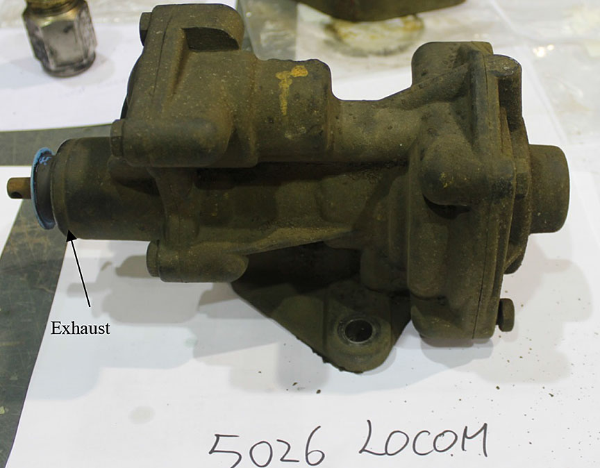
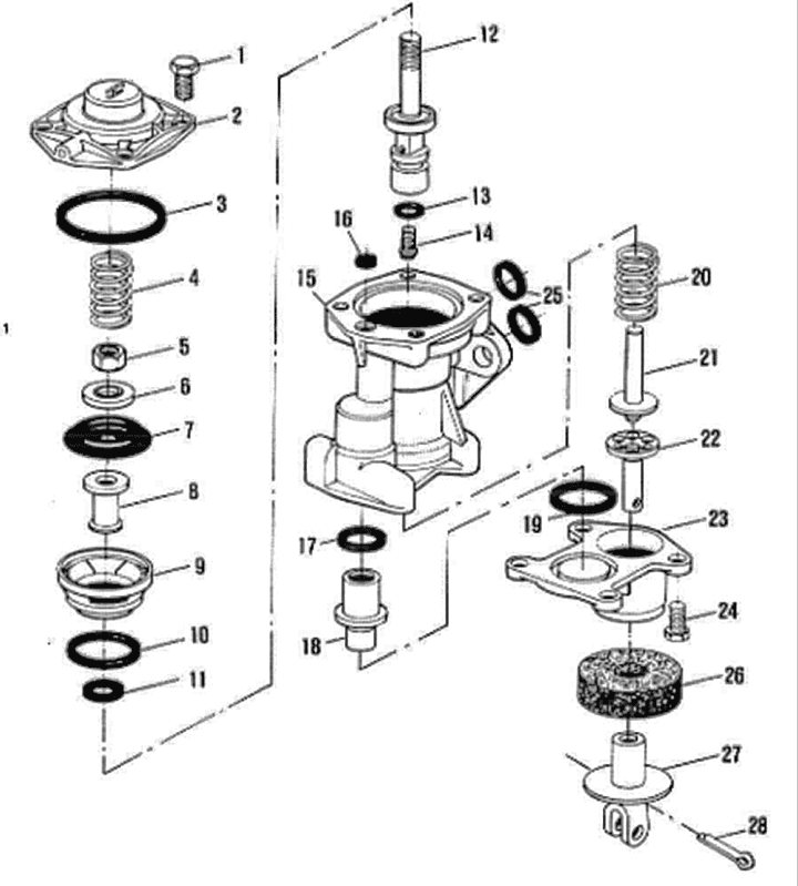
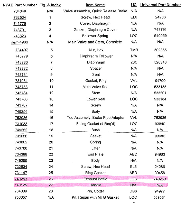
Figure 16 shows the QRB valve after it was removed from the locomotive. A blue plastic cap had been placed in front of the exhaust, pierced through by a rod sticking out from the body of the valve. A review of the parts diagram for the QRB valve (Appendix A) indicated that this rod is a component of the end plate (part #22), which sticks out of the body of the valve (part #23), goes through a hole on the baffle (part #26) and is then connected to the handle (part #27). The blue plastic cap was not indicated on the parts diagram, confirming it was not an original component of the subject valve. The function of this blue plastic cap was not clear.
2.5.5
The valve was disassembled and its components were examined for indications of wear or damage that might have caused it to malfunction. Figure 17 shows the disassembled components of the valve. Visible damage was found on two components, the retaining hole inside the body (part #23) and the lifter (part#21).
2.5.6
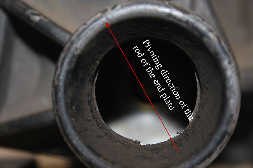
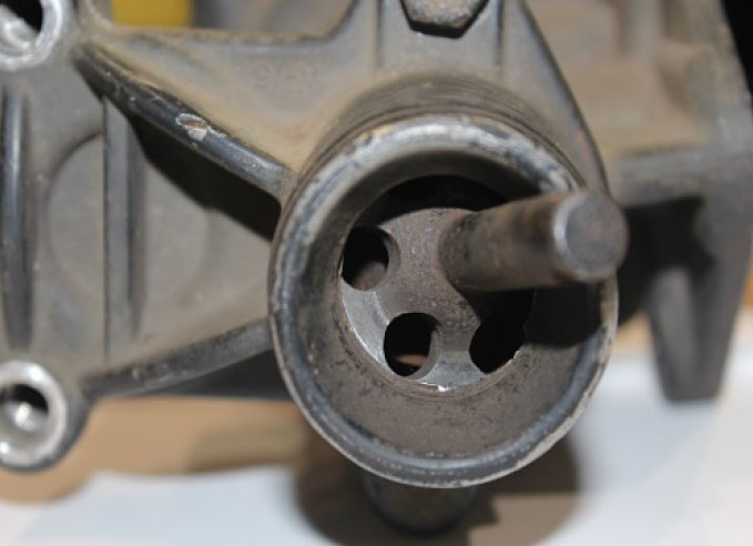
Figure 18 is a photo showing the damaged edge of the retaining hole of the valve’s body as viewed from the outside. This hole has two functions: firstly it is the exhaust hole for the brake cylinder (air) release; secondly, it is designed to retain the end plate (part #22) and to provide a circular surface for the end plate to pivot to push the lifter (part #21) in order to release the air in the brake cylinder. The damaged spot was at the exact location where the end plate pivots to push the lifter when the rod is moved in the direction indicated by the red arrow on Figure 18.
2.5.7
Figure 19 shows the damage on the retaining hole when viewed from the inside. The area highlighted by the white dotted line shows considerable wear and a damaged edge. The circular groove around the hole has disappeared in this area. It is considered that this wear damage would cause a small change (recession) in the position against which the end plate pivots, which would affect the pivoting stroke and potentially the quick release mechanism of the valve.
2.5.8
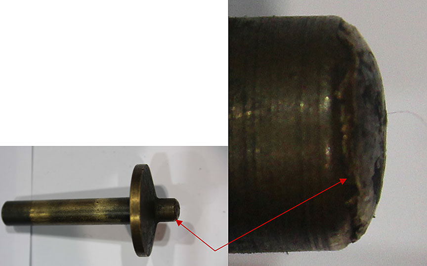
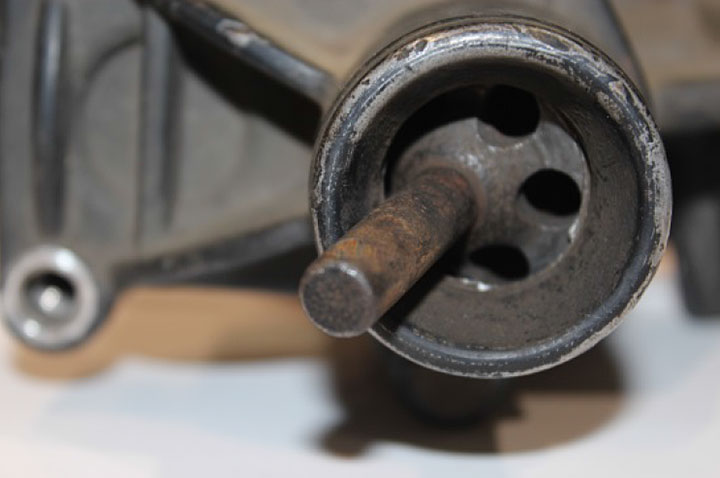
Figure 20 shows the lifter in the valve. The end of the lifter that is in contact with the end plate was slightly crushed. This would have resulted in a reduction of the length of the lifter. If this length reduction exceeded the tolerance for the device, it would have affected the functionality of the quick release mechanism.Footnote 6
3.0 Analysis
3.1 Main reservoir check valve from locomotive unit MMA-5017
3.1.1
The examination revealed the presence of dirt on the sealing areas on the disc and seat ring as well as the deformation and loss of elasticity of the rubber seal between the check valve and main reservoir, consistent with aging damage. While the dirt contamination on the disc and seat ring may result in air leakage to some extent, the deformation, loss of elasticity and cracking of the rubber seal due to aging was probably the main reason for the leaking of this check valve.
3.2 Compressor relief valve from locomotive unit MMA-5017
3.2.1
The rubber seal on the head of the pop-off stem was found to be aged, as indicated by the presence of deep grooves on its surface. However, it was unlikely that this was the reason for excessive air blowing from the valve during in-situ testing. Laboratory testing indicated that the relief pressure of the valve was reduced to 50 psi whereas the default setting was 60 psi. This was likely the main reason for excessive air blowing. It is likely that the retaining spring had sagged a bit over the years, which led to the reduction in relief pressure.
3.3 Main reservoir check valve for locomotive unit CEFX-3166
3.3.1
The examination of the valve’s components revealed that the rubber seal between the check valve and main reservoir was broken and that the O-ring between the seat ring and valve housing body was badly deformed because of the loss of elasticity due to the aging of the rubber. While contamination by an oil-dust mixture found on the disc and seat ring may have contributed to the air leaking to some extent, the broken rubber seal between the valve and main reservoir and the deformation of the O-ring were likely the two main reasons for excessive air leaking from the main reservoir of the air brake system.
3.4 Dead engine pressure regulating valve from locomotive unit CEFX-3166
3.4.1
The examination revealed a deformation of the rubber seal between the disc assembly and the base seat as well as the accumulation of particles on it, which probably affected the seal. The dust particles had a dark-red color suggesting that they originated from the outlet pipe, which was made of steel and was rusted. The badly aged rubber seal and rusted outlet pipe suggest that this valve had been in service for a long time, probably well beyond its designed lifespan.
3.5 QRB valve from locomotive unit MMA-5026
3.5.1
The QRB valve had a complex structure in comparison with the above examined check valves. Examination of the QRB valve found wear damage to the end plate retaining disc on the valve body as well as to one end of the lifter. To determine if this damage could be responsible for the malfunction of the valve, it is first necessary to understand the working principle of the QRB valve.Footnote 7
3.5.2
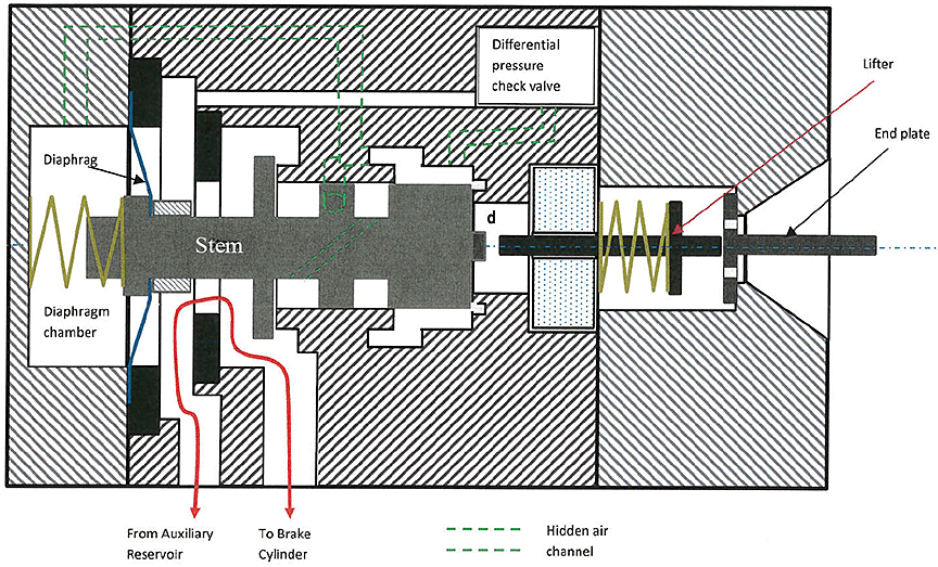
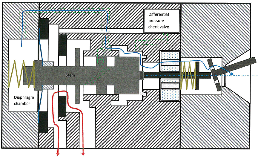
Figure 21 is a reconstructed diagram of the QRB valve illustrating its working principle. Figure 21a shows that when the rod of the end plate is not moved up, the spring pushes the lifter to the right against the end plate, leaving a gap (indicated by the letter d on Figure 21a) between the lifter and valve’s stem. When the handbrake chain is tensioned, the rod, which is connected to the handle and lever as shown in Figure 14b, moves up and the end plate pivots against the inside surface of the retaining disc on the exhaust hole. This pushes the lifter to the left, which in turn pushes the head of the valve’s stem to the left. Once a small gap appears between the head of the valve’s stem and the valve’s main air release channel, the compressed air in the diaphragm chamber is released, following the path indicated by the blue line on Figure 21b. The pressure drop in the diaphragm chamber creates a pressure differential across the diaphragm, producing sufficient force to shift the stem to the left instantly, resulting in a quick brake cylinder air release following the channel shown in Figure 21c. At the same time, the shift of the stem to the left also closes the air passage between the auxiliary reservoir and the brake cylinder in order to preserve the air pressure in the auxiliary reservoir.
Figure 21. Schematics illustrating the working principle of the QRB valve.
3.5.3
The working principle presented in the previous paragraph suggests that a reduction in the lifter’s length due to damage (Figure 20) would be expected to affect the operation of the valve. It would increase the gap between the lifter and the head of the stem, thus requiring an increase of the leverage angle of the end plate in order for the release mechanism to work.
3.5.4
The local wear and damage to the end plate retaining disc (Figure 19), against which the end plate pivots to push the lifter, is also expected to affect the operation of the valve because this wear amounts to a recession of the pivoting position along the primary axis of the valve, which would also require an increase of the leverage angle of the rod (thus, the lever) in order for the valve to work.
3.5.5
A test of the maximum pivoting stroke of the end plate indicated that the wear and damage to the retaining disc had resulted in a recession of the pivoting position by about 0.7 mm, amounting to an equivalent loss of pivoting stroke of 0.7 mm (see Appendix B)
3.5.6
The development of wear and damage to the lifter and inside surface of the retaining disc is considered to be a long term process. The use of a shim on the horizontal plate of the movable block (Figure 14a) possibly reflects the fact that at some stage of the subject QRB valve’s service history, the wear and damage to these two components had caused the malfunction of the valve. By using a shim to increase the leverage angle, the valve was made to work again. However, this was an improvised remedy rather than a repair made according to a maintenance and service standard. It is considered that at the time of this occurrence, the wear and damage to the lifter and retaining disc had further progressed, resulting in the malfunction of the valve.
4.0 Conclusion
4.1
The cause of the excessive air leakage of the main reservoir check valve from locomotive unit MMA-5017 was determined to be loss of elasticity and cracking of the rubber seal due to aging. Contamination of the disc and seat ring by an oil-dust mixture on the disc and seat ring may also have contributed to the air leakage. The advanced stage of aging of the rubber seal suggest this valve had not been inspected or serviced for some time.
4.2
The relief pressure of the compressor pressure relief valve from locomotive unit MMA-5017 was reduced to 50 psi whereas the default setting was 60 psi. It was likely that the retaining spring had sagged a bit over the years, resulting in an undesired opening of the relief valve under nominal pressure and giving rise to excessive air blowing from the head of the valve.
4.3
Examination of the main reservoir check valve from locomotive unit CEFX-3166 found that the rubber seal was broken and the O-ring between the seat ring and valve’s housing body was badly deformed, causing the excessive air leakage from the main reservoir. The advanced state of aging of the rubber seal and O-ring suggest this valve had not been inspected or serviced for some time.
4.4
The air leak from the dead engine pressure regulating valve from locomotive unit CEFX-3166 was primarily due to the aging rubber seal between the valve’s disc and base seat. Rust particles on the rubber seal probably further aggravated the air leak.
4.5
Testing and examination of the QRB valve from locomotive unit MMA-5026 identified wear damage to the valve’s lifter and to the inside surface of the retaining disc as the cause for the malfunction of the valve. Non-standard repairs had been applied to the valve’s release mechanism, suggesting that the valve malfunction was known to the operator before the occurrence.
Appendix A - Parts diagram for the QRB valve
Figure A-1: Parts diagram of QRB valveFootnote 8
Appendix B - Determination of the Maximum Pivoting Stroke of the QRB Valve's End Plate
B-1.0 Description of the testing method
B-1.1
Figure B-1 is an inside view of the QRB valve after removing the diaphragm-related components and stem in order to visualize the internal configuration of the end plate pivoting mechanism and to test the pivoting stroke along its primary axis.
B-1.2
Figure B-2 shows the test setup using a caliper and reference plate to measure the distance between the reference plate and the end of the lifter. The distance between the reference plate and the end of the lifter was measured when the end plate was not pivoted, and set as the base value.
B-1.3
The rod of the end plate was then moved to four different positions, as shown in Figure B-3. The nominal direction was the direction in which the rod would move when the handbrake is being applied. The test was repeated with a direction opposite to this nominal direction and at 90 degrees to either side. The distance between the reference plate and the end of the lifter was recorded before and after moving the rod to its maximum position (firmly against the angled wall of the exhaust) for each of the 4 different directions. The results were recorded as the stroke of the pivoting mechanism and are summarized in Table B-1.
Figure B-3. Photos showing the rod pivoted to different positions
B-1.4
It can be seen that the stroke in the nominal direction was consistently 0.7 mm shorter than in the 3 other directions. The smaller stroke was caused by the recession in the pivoting position that was experienced in the nominal direction but not in the 3 other directions.
| Direction | Nominal | 90° to the left | 90° to the right | Opposite of nominal |
|---|---|---|---|---|
| Maximum stroke (mm) | 6.0 | 6.7 | 6.7 | 6.7 |
This lab report is part of the Transportation Safety Board of Canada's investigation report R13D0054.
