Power Loss - Mechanical Malfunction
HeliQwest Aviation Inc.
Bell 205A1 N205HQ
Tumbler Ridge, British Columbia, 21 nm SE
The Transportation Safety Board of Canada (TSB) investigated this occurrence for the purpose of advancing transportation safety. It is not the function of the Board to assign fault or determine civil or criminal liability. This report is not created for use in the context of legal, disciplinary or other proceedings. See Ownership and use of content. Masculine pronouns and position titles may be used to signify all genders to comply with the Canadian Transportation Accident Investigation and Safety Board Act (S.C. 1989, c. 3).
Summary
The HeliQwest Aviation Inc. Bell 205A1 helicopter (United States registration N205HQ, serial number 30100) was performing heli-slinging operations 21 nm southeast of Tumbler Ridge, British Columbia. As the pilot was entering a hover at an altitude of about 180 feet above ground, there was a loud noise and the engine (Lycoming/Honeywell T53-17A) lost power. The helicopter descended and struck trees. The pilot, alone in the helicopter, sustained minor injuries, and the helicopter was substantially damaged. The accident occurred at about 0910 Pacific daylight time.
Factual information
The helicopter departed from camp at 0710 Pacific daylight timeFootnote 1 with the pilot and 14 seismic workers on board. After dropping off the seismic workers at a well site, the pilot flew to a staging area about three miles away, where the helicopter was refuelled. About 30 minutes later, the seismic workers called to advise that they were ready for the helicopter to begin slinging operations to move various pieces of drilling equipment. Using a 150-foot longline, 24 loads were successfully moved. The 25th load weighed approximately 2900 pounds, and it had to be moved about 100 yards and manoeuvred into place. During this operation, at about 20 feet above the ground, there was a loud "pop," followed by the sound of the main rotor blades slowing down and, reportedly, a flash of fire coming from the tailpipe of the helicopter. The pilot lowered the collective, released the load, and then raised the collective as the helicopter descended into a stand of short trees.
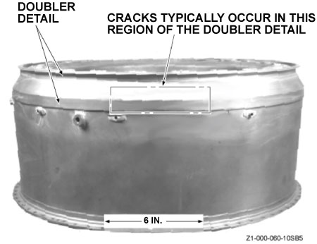
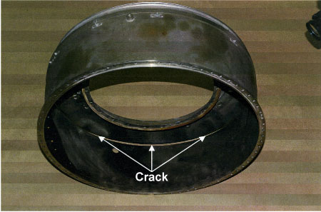
Examination of the engine revealed a large circumferential crack in the combustion chamber housing (CCH). The crack allowed high-pressure air from the engine compressor section to escape, resulting in a loss of engine power. The crack was 46 inches long and encompassed about 210° of the circumference of the chamber. It was centred on the approximate 6 o'clock position. The crack had propagated from multiple fatigue cracks initiated by corrosion pits on the inside diameter surface of a doubler joining the two main sections of the CCH (see photos 1 and 2).
Due to the manner of construction of the CCH, an internal circumferential gap exists where the two sections are joined by the doubler. The internal circumferential gap allows the accumulation of moisture and combustion products.
On the CCH involved in this occurrence, there was a previous weld repair on the doubler, and the weld had been polished and refinished as to be almost undetectable. One end of the crack terminated at this weld. It was determined that the weld was not involved in the initiation of the crack; in fact, the weld had arrested the crack.
There have been eight reported failures of these CCHs (including this occurrence), with the two latest failures occurring within a 14-day period. Two of the occurrences involved in-flight shutdowns with significant airframe damage.
A similar occurrence, on 20 January 1995, resulted in the issue, on 23 June 1995, of TSB Aviation Safety Information Letter 950024 to Transport Canada. The letter suggested that "Early detection of interior cracking may be possible during pre-flight inspections if pilots and AMEs [Aircraft Maintenance Engineers] are alert for signs of heat exposure on the cowls and liner."
The manufacturer had previously issued Service Bulletin (SB) T53-0139 on 23 July 2004 addressing CCH failures with the following two recommendations:
- An external visual inspection of the CCH for "crack-like indications," with the initial inspection to be within the next 25 gas producer (GP) cycles and every 100 GP cycles after the initial inspection. If any indication of a crack is found, replace the CCH with a serviceable unit prior to flight.
- An external visual inspection of the critical area of the CCH for weld repairs. If a weld repair is found, the frequency of inspection increases to daily until the CCH is replaced with a housing having no welds.
The CCH in N205HQ had been overhauled in June 2001, and had been in service for 2287 hours following overhaul. SB T53-0139 had been completed on 25 September 2005 at 2280 hours.
As a result of the two latest occurrences, on 28 October 2005, the manufacturer issued Revision 1 to SB T53-0139, which modified the inspection schedule in T53-0139R1 as follows:
Inspect the CCH upon receipt of the SB for existing weld repair or visible cracks, and inspect prior to the first flight of each day.
- If cracks are found, remove and replace the CCH before the next flight;
- If a weld repair is found, with no visible cracks, the engine may be operated for ferry purposes up to 5 hours, not to exceed 4 GP cycles.
SB T53-0139R1 was revised and issued as SB T53-142, which superseded SB T53-0139 and T53-0139R1.
The following TSB Engineering Laboratory report was completed:
- LP 107-05 – Combustion Chamber Housing
This report is available from the Transportation Safety Board of Canada upon request.
Analysis
The internal circumferential gap that existed in the CCH where the two sections were joined by the doubler allowed the accumulation of moisture and combustion products, which initiated and accelerated the corrosion and pitting process. Elimination of this gap by welding or other means would have prevented the corrosion.
TSB's Aviation Safety Information Letter 950024 suggested that pilots and AMEs might be able to detect cracks during pre-flight inspections. However, in several instances, no indications were visible before complete failure, and on other occasions, the cracking was only discovered by a detailed internal examination of the CCH at overhaul. Therefore, it would appear that checking external components for visible signs of heat exposure is not effective because a major failure would have to precede any heat exposure to the cowls and liner.
None of the service bulletins issued to date address a means to inspect the CCH to detect internal cracking. A periodic non-destructive inspection (such as ultrasonic) would detect the onset of internal cracking before penetration to the external surface occurs.
Weld repairs found on CCHs are assumed to have been completed to repair cracks that had penetrated to the exterior of the doubler. Due to the nature of the cracks propagating unseen inside the CCH for some time before becoming visible externally, repairs could mask the first indications of severe and widespread internal cracking until a sudden major failure occurs.
Findings
Findings as to causes and contributing factors
- The engine failed when the combustion chamber housing (CCH) fractured and high-pressure combustion air was lost.
- Internal corrosion pitting and cracking of the CCH was not detected by external inspection.
Finding as to Risk
- Service Bulletin T53-142 does not provide an adequate means of inspection to identify all corrosion cracking in the CCHs.
Safety action
Safety action taken
On 29 June 2006, the TSB issued an Aviation Safety Advisory (A060024-1) to Transport Canada regarding the inspection of the engine combustion chamber.
The manufacturer, Honeywell International Inc., has addressed the problem of cracking combustion chamber housings (plenums) in the following manner:
- Issued external report 21-12907A, Ultrasonic Inspection T53 Combustor Housing P/N 1-130-610-05/12 rev A, dated 17 November 2006. This report describes the personnel qualifications, equipment requirements and set-up, inspection sequence (calibration, inspection and post-calibration), and evaluation guidelines for the inspection of plenums.
- Pre-ordered a quantity of ultrasonic reference standards, ultrasonic transducers, and ultrasonic transducer mounting adapters to facilitate the field inspection of plenums.
- On 26 January 2007, issued Service Bulletin (SB) T53-0144, with a revision on 09 April 2007, to require inspection of the plenums with the use of the inspection kits as assembled above.
- Developed a weld repair procedure via Overhaul Repair Instruction (ORI) T41040 and Honeywell Drawing 1-130-610R16 rev A for repair and inspection of cracked plenums.
- Redesigned the plenums to address the failure modes of the existing plenums, with the new plenums designated as 1-130-610-19.
This report concludes the Transportation Safety Board's investigation into this occurrence. Consequently, the Board authorized the release of this report on .

