Loss of propulsion
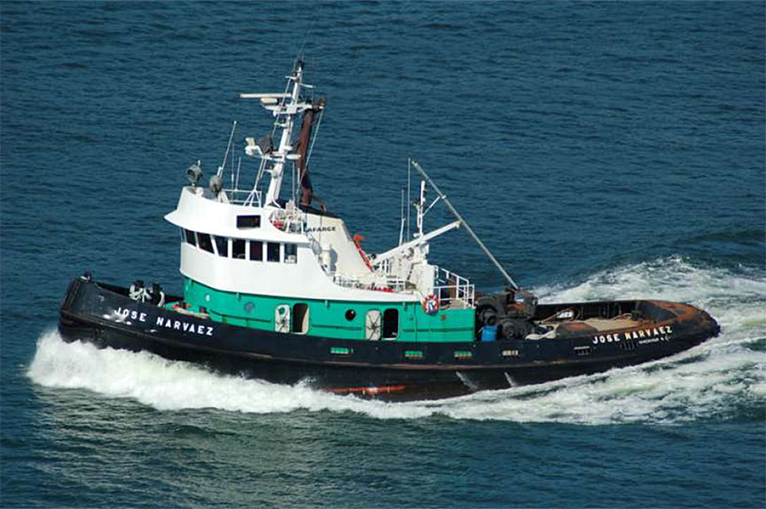
Tug Jose Narvaez with barge TCT 8000
South Arm Fraser River, British Columbia
The Transportation Safety Board of Canada (TSB) investigated this occurrence for the purpose of advancing transportation safety. It is not the function of the Board to assign fault or determine civil or criminal liability. This report is not created for use in the context of legal, disciplinary or other proceedings. See Ownership and use of content. Masculine pronouns and position titles may be used to signify all genders to comply with the Canadian Transportation Accident Investigation and Safety Board Act (S.C. 1989, c. 3).
Summary
On 11 February 2014, at approximately 0305 Pacific Standard Time, the tug Jose Narvaez, while towing the empty barge TCT 8000 down the South Arm Fraser River, British Columbia, sustained a loss of propulsion due to a main engine seizure. The tug and barge were towed back to the Lafarge marine dock and secured. The main engine was deemed a constructive loss; there were no injuries or pollution.
Factual information
Particulars of the vessels
| Name of vessel | Jose Narvaez | TCT 8000 |
|---|---|---|
| Registry/Licence number | 331836 | 836236 |
| Port of registry | Vancouver, BC | Vancouver, BC |
| Flag | Canada | Canada |
| Type | Tug | Barge |
| Gross tonnage | 149.63 | 3008 |
| Length Footnote 1 | 24.63 m (registered) | 82.83 m (registered) |
| Draught at occurrence | Forward: 3.6 m Aft: 3.6 m |
Forward: 0.84 m Aft: 0.84 m |
| Built | 1969 | 2011 |
| Propulsion | Diesel engine, type EMD645E5 driving 1 controllable-pitch propeller at 200 rpm | Non-propelled |
| Cargo | Tow | Empty |
| Crew | 5 | None |
| Registered owner | Lafarge Canada Inc. | Malaspina Marine Ltd. |
| Manager | Lafarge Canada Inc. | Lafarge Canada Inc. |
Description of the vessels
Jose Narvaez
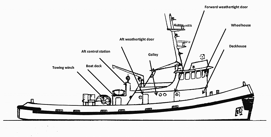
The Jose Narvaez is a single-screw, steel-hulled tug of closed construction. The weather deck comprises the main working deck (aft) fitted with a single-drum towing winch. The winch has 1 local and 2 remote emergency release stations. An enclosed deckhouse is forward of the winch and it comprises the galley and master's cabin (accessed from the forward weathertight doors on the port and starboard sides) (Appendix A). Below the main deck level, forward of the weathertight doors, are the cabins for the chief engineer, mate, and 2 deckhands.
The wheelhouse can be accessed from within the deckhouse and from the aft boat deck. It is equipped with 2 propulsion control consoles, 2 radars, an automatic identification system (AIS),Footnote 2 an echo sounder, 2 global positioning systems (GPS), and 2 rudder indicators. It is also fitted with handheld radios and a public address (PA) system that is connected to the master's and the chief engineer's cabins and the galley.
The boat deck and bridge (with a centreline helm) are located on top of the deckhouse. The boat deck is equipped with a propulsion control console, an emergency towing release switch, and the controls for the bow thruster.
Further aft of the deckhouse, at the main deck level, the engine room can be accessed through 2 weathertight doors on the port and starboard sides, and through the galley via a fire door. A stairway from this level leads down to the main machinery space where the main engine, 2 generators, the bow thruster diesel engine, and various controls are located. A controllable-pitch propeller (CPP)Footnote 3 fitted inside a steering nozzle with a single flap-type rudder is located aft.
Propulsion is provided by a single main engineFootnote 4 that drives the CPP through a reduction gear with a clutch and oil distributor box. The propeller shaft turns in a clockwise direction, when viewed from the stern, and operates at 200 rpm. The towing speed for optimum pitch is 7 knots, while the vessel's service speed is approximately 12 knots. The vessel also has a diesel-driven bow thruster that can be started and controlled from either the wheelhouse or the aft control station.
The main engine provides power for the towing winch, but there is also an emergency power take-off (PTO)Footnote 5 for the towing winch from the auxiliary generator in the engine room.
TCT 8000
The TCT 8000 is a flush-decked steel barge that operates on the west coast of Canada and the United States, and is used to haul aggregate and coal products. At the time of the occurrence, the barge was empty.
The barge was connected to the main towline by a towing bridle consisting of two 20-m lengths of steel wire rope of 32 mm in diameter. The bridle was led forward from the port and starboard bollards of the barge and shackled to the towline.
History of the voyage
At the time of the occurrence, the Jose Narvaez was based at the Lafarge marine dock in Richmond, British Columbia, and had not been operating for approximately 3 days, as it was between assignments. As the average ambient temperature was approximately 0°C, the engine was placed on pre-heat.Footnote 6 On 10 February 2014, in preparation for a scheduled trip to Beale Cove on Texada Island, British Columbia, the chief engineer boarded the Jose Narvaez at 2045Footnote 7 to take the main engine off pre-heat and prepare the machinery for departure. The master boarded at 2200 in preparation for departure, and the master and chief engineer discussed the initial status of the engine room.
At 2230, the chief engineer started up the No. 1 generator, disconnected the shore power, and powered up the main switchboard. The water level in the main engine fresh water expansion tank was observed to be low and was topped up by 200 mm on the gauge glass, adding approximately 50 litres (L).
The chief engineer then checked the oil level in the sump, added approximately 50 L of lubricating oil, opened the pre-lube valves to the main engine, and started the electric pre-lube oil pump, which was on a 30-minute timer. The pre-lube oil pump shut down after 30 minutes. The chief engineer then restarted it, and lubricating oil dripping from the exhaust and inlet valves, and substantial moisture on the valve covers were observed.
The chief engineer then carried out a pre-departure check of the propulsion controls, and verified that the controls from the 2 consoles in the wheelhouse and the one on the aft station worked satisfactorily. At 2330, the chief engineer started the main engine and, soon after, transferred controls to the master in the wheelhouse.
At midnight on 11 February, the mate and 2 deckhands boarded the vessel. The crew then conducted pre-departure checks,Footnote 8 and, along with the chief engineer, convened for a safety meetingFootnote 9 in the wheelhouse. At 0040, the vessel departed the Lafarge marine dock and made its way up the South Arm of the Fraser River to Annacis Island, British Columbia, in search of the barge TCT 8000.
At approximately 0100, the Jose Narvaez located the barge TCT 8000, and hooked up about 100 m of towline. With the barge TCT 8000 in tow, the Jose Narvaez then departed at 0125, heading downriver. As there was no rush to be at Beale Cove, the master instructed the mate to run the main engine at 650 rpm, corresponding to a steady speed of 6 knots.
At approximately 0110, the chief engineer retired to his cabin to rest until 0600. The chief engineer had not documented any main engine parameters (e.g., pressures or temperatures) in the engine log before leaving.
At 0130, the master handed over the watch to the mate and, at 0140, retired to his cabin to rest until 0600. The mate continued to keep watch with the assistance of a deckhand.
At approximately 0303, as the vessel passed through Steveston Bend, the engine room alarm panel, situated on the wheelhouse bulkhead behind the steering wheel, sounded. The mate saw that the main engine lube oil low pressure alarm was flashing, and instructed the deckhand to call the chief engineer. As the main engine was still running, the mate pulled back on the throttle to slow down the main engine. He did not silence the engine room alarm indicator, but left it flashing, as he was not sure whether cancelling it would shut off the alarm condition.
After being alerted by the deckhand, the chief engineer rushed to the engine room to check the cause of the alarm. He went through the galley and, upon opening the engine room door, saw the engine room filled with a light grey smoke. He determined that the overall visibility in the engine room was good, the main engine was still running, and there was no sign of oil spray or fire. The mate in the wheelhouse smelled steam when the engine room access through the galley was opened.
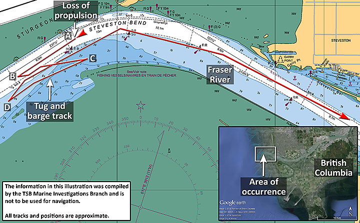
At approximately 0305, when the vessel was close to buoy S8 (Appendix B - Position A), the main engine shut down automatically, and the tug lost its only means of propulsion.
The mate sounded the general alarm, and contacted Marine Communications and Traffic Services (MCTS) for assistance. The mate also started the bow thruster from the wheelhouse, and maintained the position of the tug ahead of the barge. The master and the other deckhand came up to the bridge with lifejackets. The chief engineer returned to the wheelhouse and was instructed by the master not to enter the engine room. When all were present in the wheelhouse, the general alarm was switched off.
The mate apprised the master of the unfolding situation and of the actions taken. The master then moved to the aft station and used the bow thruster to operate the tug to follow a steady heading, keeping it ahead of the barge. At this point, the tug was still heading downriver due to its momentum, and was between buoys S6 and S8 on the river. The mate maintained contact with MCTS as well as with other vessels in the vicinity, and apprised them of the tug's position.
At 0309, under the effect of the flood tide, the Jose Narvaez changed direction (Appendix B - Position B), and started moving upriver at a speed of 0.4 knot. The master noticed that the gap between the tug and the barge was closing, and that the barge was bearing down on the tug. He advised the chief engineer to open up the engine room doors to ventilate the engine room, and to start the emergency towing winch. The engine room vent dampers were still open to clear the smoke. The engine room fans were switched off, but the fuel shut-offs were not activated.
At approximately 0313, the stern of the Jose Narvaez made contact with the barge TCT 8000; the tide was still flooding at that time, and the barge was dragging the tug upriver and drifting into shallower waters.
At approximately 0319, when the smoke cleared and conditions were safe to go into the engine room, the master requested the chief engineer to start the second auxiliary generator and engage the emergency power take-off (PTO) for the towing winch. The 2 deckhands continued with their standby duties outside the engine room entrance. The chief engineer started the No. 2 generator, and set the valve system in order to engage the PTO, but the PTO did not function as intended. The chief engineer went into the engine room a second time and corrected the air valve position. Meanwhile, the crew kept the anchor and life rafts ready for deployment, if required.
The flood tide was still moving the tug and barge up the river at a speed of 0.4 knot. The chief engineer attempted to restart the main engine. The fresh water expansion tank water level had dropped below the gauge glass; there was no indication of the level in the tank. Furthermore, steam was coming out of the fresh water expansion tank overflow.
Additionally, the crankcase high-pressure detectorFootnote 10 had activated, sounding an alarm on the engine room panel, and the built-in indicator on the detector had popped out. There was no oil outside the main engine crankcase doors. There were no other alarms on the panel, and the chief engineer returned to the main deck and stood by the towing winch.
At approximately 0322, the master winched the barge closer to the tug. The tug and barge had drifted toward shallower waters; the water depth at this point varied from 3.6 m to 4.6 m. The master continued to operate the bow thruster to steer the tug so that the barge was kept behind the tug as they drifted upriver.
At 0345, the tug Pacific Force advised the Jose Narvaez that it was on its way to assist. At 0400, the assist tug Pacific Force arrived and put its bridles on the tug's forward bow bitts; the tug had by now drifted to the south side of buoy S8 (Appendix B - Position C). The Pacific Force, with the Jose Narvaez under tow, waited for the traffic to clear. When the way was clear, the Pacific Force towed the Jose Narvaez and barge TCT 8000 down the river, avoiding shallow waters and river traffic. The barge was still askew behind the tug.
At 0420, at the request of the Jose Narvaez, the tug Seaspan Tempest, which was heading downriver, turned and aligned the barge TCT 8000 behind the Jose Narvaez, now facing upriver behind the Pacific Force (Appendix B - Position D).
After the tug and barge were aligned upriver, the Pacific Force towed the combination to the Lafarge marine dock and, at 0725, secured the Jose Narvaez and the barge TCT 8000.
Damage to the vessels
Jose Narvaez
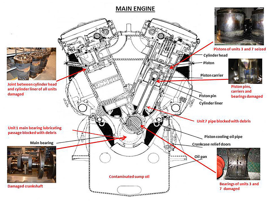
The damage to the main engine was not immediately evident. When the engine was dismantled (Appendix C) post-occurrence by a workshop assigned by Lafarge, the following observations were made:
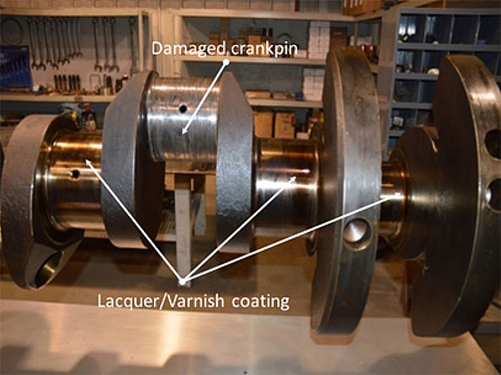
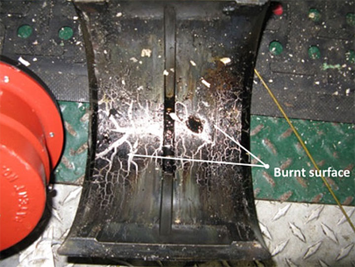
- Units 3 and 7 crankpin and bearings were damaged, and power packs had seized (Photo 2 and Photo 4).
- Piston skirts and pins, and cylinder liners showed evidence of scuffing and overheating, indicative of a lack of lubrication; piston skirt showed signs of blow-by of combustion gases.
- Connecting rods and carriers showed high heat discolouration.
- Insert bearings had exposed bronze, and showed evidence of high heat and extreme overloading.
- No. 1 main bearing tube was partially blocked with a piece of hard carbon material.
- Left bank manifold pipe in way of the No. 7 piston cooling tube was found partially blocked with debris.
- Lacquer formation on the crankpins and inside the piston cooling spaces (Photo 2).
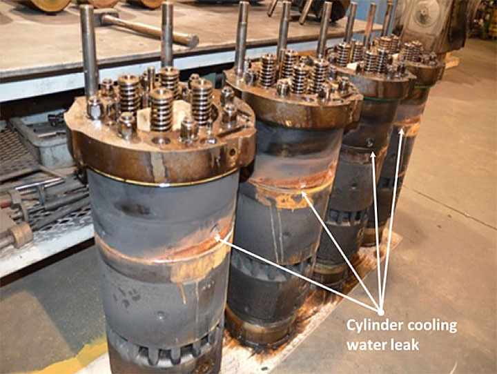
- Loss of cylinder cooling water from all units above the joint between the cylinder heads and the liners, due to gasket damage (Photo 3).
- Both cylinder cooling fresh water pumps and main cooling water pipes were contaminated with lubricating oil.
- Sump lubricating oil had emulsified and also showed signs of oxidation, as indicated by the burnt surface of the bearing shell (Photo 4).
TCT 8000
There was no damage to the barge.
Lafarge Canada, Marine Division
Lafarge North America is a large, diversified supplier of construction materials; its products include cement, ready-mix concrete, gypsum wallboard, aggregates, and asphalts. Lafarge opened the Richmond Cement Plant in British Columbia in 1956. To ensure a constant supply of aggregates, limestone and raw materials for the cement plant, Lafarge set up a Marine Division to transport raw materials from Beale Cove on Texada Island. The marine dock is located at the cement plant in Richmond; tugs and barges usually tie up at the dock between sailings, and for storage and maintenance purposes.
The main office of the Marine Division is located at Port Kells, British Columbia, and addresses dispatch,Footnote 11 operations, managerial functions, and plans scheduling details including downtimes for maintenance purposes. The Marine Division is managed by 6 employees and supported by clerical staff common to all departments and not specifically assigned to the Marine Division. Personnel from other departments usually join the Marine Division as dispatchers. The Marine Division Manager reported to the vice-president of Greater Vancouver Area (GVA) Aggregates, who in turn reported to the vice-president/general manager GVA Market and Aggregates Western Canada.
Lafarge Marine Division owns 3 tugs, and has leased or rented barges ranging from 3600 to 8000 in gross tonnage. Although they normally serve Lafarge, the tugs and barges are also sometimes leased to other companies.
The tugs are crewed by 2 sets of crew members per vessel who work on a 6 on-6 off watch. The masters maintain a 0600-1200 watch, and the mates maintain a watch of 1200-1800, and work a shift of 5 to 6 days. Additionally, other personnel are available as required as relief. The chief engineers usually maintain the same watch as the masters, but are available whenever required.
The Jose Narvaez was routinely manned by two 5-person crews on rotation, consisting of a master, mate, 2 deckhands and an engineer, who live on board for the duration of their shift. The 2 sets of crew members normally rotated their shifts every Sunday. During the change of shift, there was no formal handover, nor was any required by the company.
Personnel certification and experience
Master
The master of the Jose Narvaez held a Master 500 Gross Tonnage Near Coastal certificate and had been employed on tugs since 1998. The master had held various positions on board the Jose Narvaez since 2002, and had served as the master since 2008.
Mate
The mate of the Jose Narvaez held a Master 500 Gross Tonnage Near Coastal certificate, had been employed as a mate or relief master since 2003, and had been sailing for 28 years in various positions.
Chief engineer
The chief engineer held a third-class engineer certificate and was limited to serving as a chief engineer on motor vessels of less than 1500 horsepower. The chief engineer had been employed as an engineer with Lafarge Canada Inc. since 1990. He had been a chief engineer on the Jose Narvaez since 1990, and had been sailing for 40 years in various positions.
Maintenance manager
The maintenance manager had a millwright and welding ticket, and had worked with various companies prior to joining Lafarge, on various projects, including the maintenance of shore-based heavy duty equipment. At Lafarge, the maintenance manager worked on maintenance projects, and then joined the Marine Division as a dispatcher, eventually being promoted to the marine maintenance manager's position in 2013.
Shore engineer/lead hand
The shore engineer held a millwright and welding ticket. He had been working with Lafarge on various projects since 1972, including the maintenance of shore-based heavy duty equipment. The shore engineer was transferred to the Marine Division in 1984 as the lead hand, and since then had been maintaining the various tugs and barges, including the conducting of shipyard repairs.
Vessel certification
The vessel was crewed, equipped, and certified in accordance with existing regulations, and was last inspected by Transport Canada Marine Safety and Security (TCMSS) in 2011. In addition to inspections fulfilling certification requirements, the vessel also underwent periodic general and special inspections for the reciprocating enginesFootnote 12 and unfired pressure vessels.Footnote 13 The vessel did not have a safety management system (SMS) in place, and none was required.
Environmental conditions
The weather around the time of the occurrence was clear. The visibility was good, and the wind was a light breeze at 5 to 10 knots. At the time of the occurrence, the tide was flooding and was recorded as 1.13 m.
Main engine
The main engine is of the “V” type with 45° angle between cylinder banks. It consists of 8 cylinders, and operates on the 2-cycle, single-acting principle (Appendix C). It develops 1450 brake horsepower at 900 rpm, while its idle speed is 325 rpm. At the time of the occurrence, the main engine had 200 111 running hours.
Cylinder cooling system
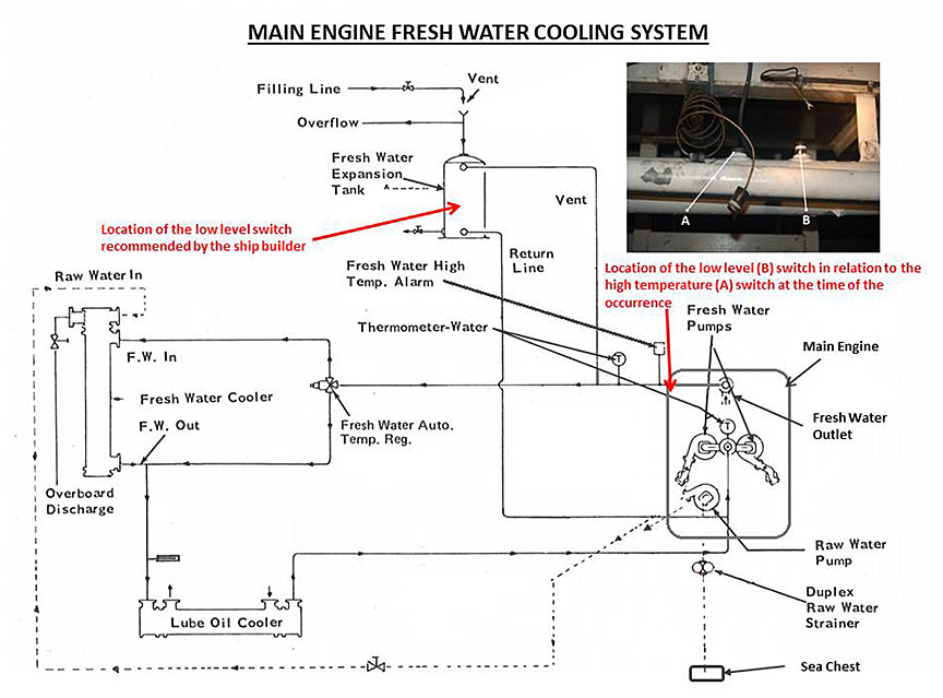
The cylinder cooling system consists of engine-driven fresh water pumps, a raw water pump, and a fresh water cooler.Footnote 14 Each cylinder liner is individually supplied with fresh water, and the water enters the cylinder head through 12 discharge holes, each consisting of a Teflon heat dam and a silicone water seal, at the top of the liner. A fresh water expansion tank of a capacity of approximately 135 L is connected to the main engine cylinder cooling water system for the purpose of expansion and maintaining a positive head at all times. The tank has a gauge glass for visual indication of the water level. A low level alarm switch was fitted on the main engine fresh water outlet manifold (Appendix D).
Lubrication system
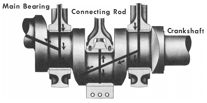
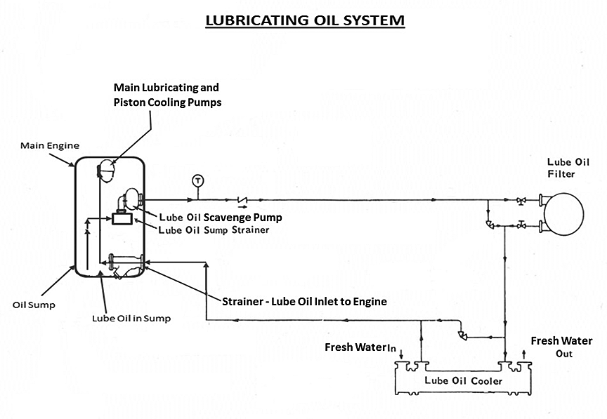
The lubrication system consists of engine-driven main lubricating and piston cooling pumps, an engine-driven scavenge pump, lube oil coolerFootnote 15 where the lubricating oil is cooled by the cylinder fresh water, and an oil sump where excess oil in the system is collected (Appendix E). A pipe is located at each cylinder to direct a stream of oil through the piston carrier to the top of the piston. Drilled oil passages in the crankshaft conduct oil to the main bearings, connecting rod bearings, and other parts of the engine. The main engine system requires approximately 990 L of Society of Automotive Engineers (SAE) 40-grade oil.
Previous occurrences
Several occurrences involving propulsion failures on the Jose Narvaez had been reported to the TSB in the past. In November 2010, the tug lost a seal in a CPP while towing a barge off Halibut Bank Buoy, Strait of Georgia, British Columbia.Footnote 16 The company reported that, at that time, the vessel was also experiencing issues with propeller pitch control. In July 2011, the tug sustained a major engine failure (failure of the power pack) while inbound the Fraser River.Footnote 17 In May 2012, the tug ran aground in Steveston, British Columbia, after another power pack failure.Footnote 18 In June 2013, the tug reported an engine failure (failure of the power pack) with a crankcase explosion in Georgia Strait, British Columbia.Footnote 19
There was no information to indicate that the company had informed TCMSS of the previous breakdowns and replacements of the power packs, or that TCMSS had followed up on these occurrences.
Lubricating oil contamination
Diesel engine lubricating oils may become contaminated by
- adventitious solid matter and metal particles resulting from wear;
- carbonaceous products from the incomplete combustion of fuel;
- acidic water, resulting from the condensation of blow-by gases;
- cooling water;
- carbonaceous material formed by the breakdown of the lubricating oil;
- ash from the lubricating oil additives; and/or
- oxidation.Footnote 20
When lubricating oil is contaminated, the additive concentrate is depleted beyond acceptable limits, and the oil loses essential properties including alkalinity, detergency, and dispersancy. Without vital reserves of these properties, the oil no longer provides satisfactory protection of the engine in being able to limit harmful deposit formations from oxidized oil and other contaminants, or maintain adequate control over the corrosive products of combustion.
Four months before this occurrence, internal leaks of the lube oil cooler were detected. Lafarge was informed, and it was decided to stop treating the fresh water cooling system with the corrosion inhibitor and anti-freeze solution that was being used to keep the cylinder cooling water in optimum condition. At the time of the occurrence, Lafarge was investigating the possibility of obtaining a different cooler to rectify the problem, but no actions had yet been taken.
Engine alarm system
In addition to other machinery alarms, the alarm panels in the wheelhouse and in the engine room include warning lights for the following: high crankcase pressure, jacket water high temperature, low oil level and low lube oil pressure, main engine fresh water expansion tank low level, and main engine overload.
The wheelhouse alarm panel consists of only 2 push buttons: 1 alarm silence button and 1 alarm test button. The engine alarm panel, in addition to those 2 buttons, also contains an “on/off” switch and an alarm reset push button. Additionally, 1 external alarm siren installed in the machinery space is powered from the engine alarm panel that is installed in the circuit. Industry practice is to test the alarm panel prior to operation, as part of the pre-departure checks. In this case, the alarm panel was switched on but, as there were no directions from the company, it was not tested prior to departure.
Main engine maintenance
Maintenance documentation
The engine manufacturer published various maintenance instructions and updates pertaining to main engine operations, such as the following:
- Maintenance Instructions – Lube Oil Coolers – M.I. 927
- Maintenance Instructions - Scheduled Maintenance Program Marine Units -567, and 645 Turbocharged Engines – M.I. 1722
- Maintenance Instructions – Engine Coolant – M.I. 1748
- Maintenance Instructions – Flushing Diesel Engine Lubricating Oil System – M.I. 1757
- Maintenance Instructions – Lubricating Oil for Marine Engines – M.I. 1760
- Maintenance Instructions – Crankcase Pressure Detectors – M.I. 259.
There was no indication that the company had requested any of these instruction documents for the guidance of the vessel crew, and none were found on board the vessel.
Recommended maintenance schedule
The engine manufacturer recommended that, on a monthly basis, an oil sample should be sent for analysis to monitor the suitability of the oil for continued use. In this occurrence, the vessel's crew reported submitting oil samples to Lafarge every 1200 main engine operating hours and not as recommended by the manufacturer. In one of these instances, the chief engineer had noticed a substance on the fresh water side of the engine. When a sample was sent for analysis, it was declared by the laboratory to be sludge. On a couple of other occasions, the samples were identified to have water contamination. At the time of the occurrence, copies of the analysis reports were not available through Lafarge or on board the vessel.
Every 1400 hours, the manufacturer recommended that all protective devices be tested, namely, the crankcase high-pressure detectors, the lube oil low level alarm, the lube oil low pressure alarm, and the over-speed trip.
Every 2000 hours, the crankcase, crankshaft, and connecting rods, pistons and liners were to be inspected, and the engine water system checked for leaks.
Every 4000 hours, the manufacturer specified that the sump was to be cleaned and the oil changed. On the Jose Narvaez, a partial replacement of the engine oil was being performed approximately every 2400 hours. This oil change was based on the engine operating hours and was carried out by the vessel's chief engineer; the hours were recorded in the engine log. However, only 1 major oil change (800 L) due to water contamination, and 2 partial changes (one of 100 L due to water contamination and the other of 250 L) in the past 2 years were noted in the oil analysis report that was obtained from the oil analysis laboratory. The oil sump was not cleaned.
Every 8000 hours, the floating header seal of the lube oil cooler was to be renewed.
Every 16 000 hours, the manufacturer advised that a sample of the engine cooling water should be analyzed for effectiveness against corrosion.
Every 24 000 hours, the lube oil cooler and fresh water coolers were recommended to be inspected, cleaned, and tested.
There was no information to indicate that the recommended maintenance for 1400, 2000, 8000, 16 000 and 24 000 hours, was being carried out in accordance with the recommended schedule.
Flushing of the lubricating oil system
According to the engine manufacturer, performance of the appropriate scheduled maintenance of filter and oil changes, under normal operating conditions, is sufficient to keep the engine lubricating oil system functioning properly. It is not necessary or recommended to completely flush and clean out the main engine lubricating oil system as a routine maintenance practice. However, the manufacturer specifies that the system should be flushed in circumstances where
- a part failure has occurred;
- oil has been contaminated with an excessive amount of water or permanent type of anti-freeze;
- the engine is very dirty or badly lacquered; or
- the engine is being removed from storage.
The investigation determined that the system had not been flushed out and cleaned completely, despite the failures experienced in previous occurrences, for instance, where the power pack failed.
Maintenance management system
A maintenance management system is a paper- or software-based system that can assist vessel owners and operators in carrying out methodical and timely inspections and maintenance. Such a system can be used to establish maintenance and inspection intervals, and to define the methods for maintenance tasks. In addition, it can be used to assign responsibility for maintenance tasks.
The Marine Division at Lafarge had recently transitioned the planned maintenance system from a paper-based system to a computerized spreadsheet-based program for all tugs and barges. The program could be accessed on the phones of key personnel, and was available for viewing by all crew members on all tugs. Although the program was being used to order spare parts and consumable stores items as well as to requisition repairs, the functions of the program associated with planning maintenance intervals, defining the methods and frequency for maintenance, and assigning responsibility for maintenance were not fully utilized.
Equipment deficiencies were not recorded in the vessel log, nor were written records kept of the equipment that had been repaired ashore and returned to the vessel. No records of major overhaul services or repairs assigned to an outside workshop (such as replacement of power packs) were available either through Lafarge or on board the vessel.
Safety management
The principal objective of an SMS on board vessels is to ensure safety at sea, prevent human injury or loss of life, and avoid damage to property and the environment. Safety management involves individuals at all levels of an organization, and requires that a systematic approach be taken in the identification and mitigation of operational risks.
One aspect of safety management on board vessels is ensuring crew familiarization, whereby all crew members receive orientation on vessel arrangements, installations, and equipment, with an emphasis on the crew members' specific duties, particularly those related to their tasks in case of emergency.
The engine room did not have documented procedures for managing emergencies, such as the need to engage the emergency towing winch in cases of main engine failure, and the vessel did not carry out associated drills. Additionally, there were no vessel-specific documented procedures, instructions or checklists.
Analysis
Events leading to the loss of propulsion
As the Jose Narvaez rounded Steveston Bend at a speed of approximately 6 knots and at 650 rpm, low pressure was detected in the main engine lubricating oil system, causing an alarm to sound in the wheelhouse engine room alarm panel. Soon after, the main engine seized, the pressure within the crankcase increased (activating the pressure detector switch alarm), and the main engine automatically shut down. Propulsion was then lost.
The investigation determined that the lubricating oil in the engine was contaminated. As the lubricating oil system (including the oil sump) had never been completely flushed out and cleaned after a major overhaul, and with the lube oil cooler leaking internally, the lubricating oil had been progressively contaminated with the products of combustion, fresh water, and/or anti-freeze. Furthermore, as the lube oil pressure was higher than the cylinder cooling water pressure, oil from the engine was observed, during operation, to be leaking into the fresh water system through holed tubes in the lube oil cooler. When the vessel was docked (between assignments), the cooling water system had a positive head by virtue of the higher location of the fresh water expansion tank above the lube oil cooler and, as the pre-heat pump was on, the fresh water leaked into the lubricating oil system, thus contaminating the lubricating oil.
This contaminated oil resulted in 2 choked oil cooling pipes and a loss in pressure due to water contamination. Additionally, the deteriorating oil condition due to oxidation led to lacquer and varnish formation on the bearing surfaces inside the engine, subsequently affecting bearing lubrication.
The contamination of the oil also resulted in loss of lubrication and piston cooling, and cylinder units 3 and 7 overheated. This overheating damaged the rubber seal between the cylinder head and cylinder liner, causing the cylinder cooling water to leak into the main engine crankcase. This leakage, in turn, depleted the water level from the other cylinders, which exacerbated the overheating of the rest of the engine, eventually leading to its seizure and the loss of propulsion.
Maintenance management system
The engine manufacturer normally provides detailed information on what maintenance should be carried out and when, to ensure the optimum operation of critical vessel machinery. As part of the maintenance program, it is important that vessels have clearly documented maintenance procedures to ensure that inspections and repairs are carried out as is advised by the manufacturer for safe operation.
While Lafarge had recently installed a computerized program for requisition of repairs and spare parts, the program was not used, in this occurrence, to manage the maintenance of the Jose Narvaez based on the manufacturer's recommended schedule. For example, the crews were not checking the oil condition on a monthly basis for continued use, nor were they inspecting, cleaning, or testing the lube oil cooler, or completely flushing out and cleaning the lubricating oil system after a major engine failure. As this maintenance was not done according to the recommended schedule, the engine lubricating oil became contaminated over time, thereby increasing the risk of damage to the engine.
If companies do not ensure that engine maintenance is conducted according to the manufacturer's recommendations, the engine may not function as intended, thereby increasing the risk of an accident.
Low level alarm position
To ensure early warning of unsafe conditions, it is essential that alarms be fitted correctly and functioning properly.
In this occurrence, the low level alarm switch was fitted to the cylinder cooling water outlet piping. It was not fitted to the fresh water expansion tank (Appendix D), as was recommended by the vessel builder. As its position on the outlet piping was lower than the fresh water expansion tank, an alarm would not sound if the tank level dropped completely. In this case, the tank emptied out and the alarm did not sound. If it had sounded, the vessel crew could have been alerted to the significant loss of water, and would have had an earlier opportunity to take action.
Furthermore, because of the alarm's position in the engine, it had become plugged by sludge from the contamination of the fresh water, and thus was not functional at the time of the occurrence.
If an alarm system is not fitted in the recommended position, the crew may not be alerted to an unsafe condition and may be precluded from taking timely action.
Safety management
Effective safety management requires individuals at all levels of an organization to be actively involved in the identification and management of risks associated with their operation. It involves a formal, documented, and systemic approach that helps ensure that individuals at all levels have the knowledge and tools to effectively manage risk, as well as the necessary information to make sound decisions in any operating condition.
While safety management systems (SMS) are widely recognized as effective methods for assessing risk in the marine sector, not all organizations are required to have a formal SMS in place. It is nonetheless important that such organizations work toward the development of a strong safety culture,Footnote 21 whereby integral components of safety are managed to mitigate risk.
The Jose Narvaez was not required to have an SMS in place. However, it may have benefitted from a formalized approach that would ensure that crew members were provided with tools, procedures, and resources to effectively manage risk and maintain an effective operation. In this occurrence, deficiencies in operations included the following:
- On-board documentation to support crew members on aspects such as training, familiarization, drills, and maintenance, was extremely limited. For example, the engine manufacturer maintenance documentation was not on board the vessel.
- The vessel crew did not maintain adequate record-keeping, including records of maintenance being done and vessel log entries.
- The company did not provide the crew with checklists to assist with the operation of the vessel or procedures related to maintenance.
- In each change of shift, there was no formal handover required.
- The company also did not provide guidance on the type of drills to be performed, nor on safety procedures to be followed in case of an emergency.
If companies do not provide an adequate framework for the management of safety, which includes the implementation of procedures, documentation, and adequate record-keeping, there is an increased risk that operational hazards will not be identified.
Findings
Findings as to causes and contributing factors
- The lubricating oil was contaminated with the products of combustion, fresh water, and/or anti-freeze, as the system had never been completely flushed out and cleaned after past major engine failures, although this was recommended by the manufacturer.
- The lube oil cooler was not maintained as per the manufacturer's recommendations, and developed internal leaks that further contaminated the lubricating oil system with fresh water and anti-freeze.
- The contaminated lubricating oil resulted in 2 choked oil cooling pipes, lacquer and varnish formation on the bearing surfaces (affecting bearing lubrication), and a loss in pressure.
- The loss of lubrication and piston cooling that resulted from the contaminated oil caused cylinder units 3 and 7 to overheat. This overheating damaged the rubber seal between the cylinder head and liner, causing cylinder cooling water to leak into the main engine crankcase. This exacerbated the overheating of the rest of the engine, and eventually led to its seizure and the loss of propulsion.
Findings as to risk
- If companies do not ensure that engine maintenance is conducted according to the manufacturer's recommendations, the engine may not function as intended, thereby increasing the risk of an accident.
- If an alarm system is not fitted in the recommended position, the crew may not be alerted to an unsafe condition and may be precluded from taking timely action.
- If companies do not provide an adequate framework for the management of safety, which includes the implementation of procedures, documentation, and adequate record-keeping, there is an increased risk that operational hazards will not be identified.
Safety action
Safety action taken
Lafarge Canada Inc.
Following the occurrence, Lafarge initiated the following actions:
- Establishment of a weekly meeting, within the Lafarge Marine Division, to ensure review of safety procedures, drills, and preventive maintenance at the beginning of a shift.
- Replacement of the main engine and the cooling system, including upgrade to the monitoring system and alarm panel.
This report concludes the Transportation Safety Board's investigation into this occurrence. The Board authorized the release of this report on . It was officially released on .
Appendices
