Main-track train derailment
Canadian Pacific Railway
Freight train 356-196
Mile 45.62, Taber Subdivision
Near Burdett, Alberta
The Transportation Safety Board of Canada (TSB) investigated this occurrence for the purpose of advancing transportation safety. It is not the function of the Board to assign fault or determine civil or criminal liability. This report is not created for use in the context of legal, disciplinary or other proceedings. See Ownership and use of content. Masculine pronouns and position titles may be used to signify all genders to comply with the Canadian Transportation Accident Investigation and Safety Board Act (S.C. 1989, c. 3).
Summary
On 30 November 2008, at 1604 mountain standard time, Canadian Pacific freight train 356-196, proceeding eastward from Lethbridge to Bellcott, Alberta, derailed 18 empty covered hopper cars at Mile 45.62 of the Taber Subdivision near Burdett, Alberta. No dangerous goods were involved and there were no injuries.
Ce rapport est également disponible en français.
Factual information
The train
The train consisted of two locomotives, 112 empties, weighed 3481 tons and was 6729 feet long. The train crew, a locomotive engineer and a conductor, took control of the train in Lethbridge, Alberta. They met fitness and rest standards and were qualified to operate trains on the Taber Subdivision.Footnote 1 Neither the locomotive engineer nor the conductor noted any irregularities or problems with the train between Lethbridge and the point of derailment.
Recorded information indicates that the train was travelling at 35.2 mph when a train-initiated emergency brake application occurred at 1604.Footnote 2
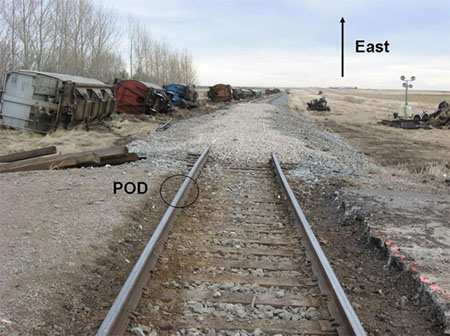
After making the necessary emergency broadcast and notifying the rail traffic controller (RTC), the conductor performed an inspection and discovered a total of 18 cars derailed; the 93rd through the 110th inclusive. Five cars were upright and 13 were on their sides, all on the north side of the track (see Photo 1).
Weather
The weather was cloudy with unlimited visibility and a temperature of 1°C.
Rolling stock
There was no evidence that the condition of the 93rd car, the first car to derail, contributed to the derailment. After the derailment, the head-end portion of the train continued on and passed over the wheel impact load detector (WILD) at Mortlach, Saskatchewan, Mile 26.1, Swift Current Subdivision, west of Moose Jaw, Saskatchewan. The train preceding the derailment train, 674-103, had passed over the same detector approximately 12 hours earlier. No impacts exceeding Canadian Pacific (CP) Railway's threshold for removal were recorded for either train.
Particulars of the track
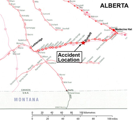
The method of train control on the Taber Subdivision (see Figure 1) is the Occupancy Control System (OCS), authorized by the Canadian Rail Operating Rules (CROR) and supervised by a rail traffic controller (RTC) in Calgary. The maximum speed is 40 mph for freight trains. This is Class 3 trackFootnote 3 as defined by the Railway Track Safety Rules.Footnote 4 The line carries an average of 28 million gross tons (MGT) of traffic per year.
The derailment occurred in the vicinity of the crossing at Mile 45.62 in a 2-degree, 30-minute right-hand curve in the direction of travel on a 0.2 per cent descending grade. The north (high) rail in the crossing was broken in five places. The point of derailment (POD) was determined to be at the break between the 2nd and 3rd tie, approximately two feet from the east edge of the crossing planks (A-A, Photo 2). Inspection of the west fracture face at this location revealed the presence of a transverse detail fracture in the upper gauge corner. The gauge corner and running surface on each side of the POD break displayed head checking, shelling,Footnote 5 and some flaking. Heavy batter was observed on the head of the east end matching rail piece.
The breaks were in a 43-foot long, 115-pound 1972 Algoma maintenance rail. This rail had 3/8 inch vertical wear and 1/8 inch flange wear, within the 115 pound condemnable rail wear limit specified in CP's Redbook of Track Requirements. The south (low) rail was 1997 115-pound Sydney carbon continuous welded rail (CWR). The rails were installed on 14-inch, double-shoulder tie plates fastened on hardwood ties with four spikes per tie plate. The ties and crushed rock ballast were in good condition and the rails were box-anchored at every tie on both sides of the crossing. The road was gravel-surfaced and the crossing was equipped with standard reflectorized crossing signs (SRCS).
Track inspections and maintenance
The track was inspected by certified track inspectors with a hi-rail vehicle on 24 November 2008 and again on November 28 with no serious defects noted. No surfacing or tie replacement work was done in the area of the derailment in 2008. The crossing was reconstructed in 1995 and the planks were replaced at that time. Ballast was replaced and surfacing through the crossing was done in 2005. Drainage and surface through the crossing were good.
No urgent or priority geometry defects were detected in the derailment area by CP's track evaluation car tests conducted on May 12 and September 9.
Laboratory analysis
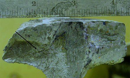
Arrangements were made with CP to examine five mating pieces of a 17-foot, 8-inch long section of the north rail, including the POD at its Test Department Laboratory in Winnipeg (see Photo 2). The west end was cut and the east end had a break. From west to east, in the direction of travel, the breaks occurred at 23 inches, 50 inches, 84 inches, 150 inches, and 212 inches (the east end). The fourth piece from the west end, between the third and fourth breaks, contained a four-hole temporary joint. The analysis revealed three of the five breaks displayed pre-existing detail fractures (DFs) extending from the gauge corner on the fracture faces with the largest at the first break from the west end. Photo 3 (break A-A) shows a DF of approximately 20 per cent of the rail head's cross-section area. This pre-existing defect initiated in an area of head checking and flaking that acted as a stress raiser. This led to a brittle transverse fracture and failure of the rail under the train. The east side of the break exhibited impact marks. Based on the size of the DFs and the severity of the impact facets, break A-A was identified as the primary fracture and the POD.
The four other breaks also displayed impact damage, but to a much lesser degree.
Arrangements were also made to perform a visual inspection, macroscopic inspection, and metallographic inspections. In addition, chemical analysis and hardness testing were conducted. The analysis determined that the rail's chemical composition and hardness were considered typical for carbon steel rail rolled in 1972. There was no visible evidence of any material and/or manufacturing defect in the rail that could have caused or contributed to the failure.
Rail testing
Detail fractures grow beneath a rail's surface and can only be detected by ultrasonic inspection. The Railway Track Safety Rules require Class 3 track to be inspected for internal defects at least once per year. However, according to CP's Standard Practice Circular (SPC) 27, Rail Testing Frequency and Remedial Action for Defective Rails, the Taber Subdivision, as Class 3 track with 15 to 30 MGT, would have required two tests per year. For this track, the frequency of inspections exceeded all requirements,Footnote 6 with records indicating that there were four ultrasonic rail tests conducted on the Taber Subdivision prior to the derailment, with a total of five tests done in 2008 (see Appendix B).
A transverse detail defect was reported at Mile 43.64 on May 6 and a defective plant weld or a butt weld (DWP) at Mile 44.98 on 13 August. Only one defect was detected in the area during the most recent test conducted prior to the derailment on 17 October—a DWP at Mile 48.6. The October 17 test was conducted by Sperry Rail Services (SRS) Car 965, which is equipped with the latest ultrasonic and induction testing technology (See Appendix A) and operator analysis tools. Although there were test equipment responses in the derailment area, they were attributed to rail surface condition and not defects.
Sperry filed a Rail Detection Exception Report, which indicated the rail between miles 45.55 and 45.8 was untested due to head checking.
Ultrasonic inspection is the primary method used to detect internal rail defects and to control the risk of rail failures. Over the years, improvements have been made in the field of rail testing, including operator training, additional probes positioned at different angles, and improvements to defect-recognition software. This has proven to be a reliable and economical testing method, but with limitations. The detectability of a detail fracture within a fatigue condition is dependent on the size and orientation of the transverse component and can be influenced by rail surface conditions such as the presence of grease or dirt on the rail's head, head checking, and internal shelling.
Rail
The POD was in a 43-foot long piece of Algoma 115-pound RE rail rolled in 1972 and bolted-in as a maintenance rail on 26 April 2005. The rail on each side of this rail was 115-pound RE CWR rolled in 1974 cascaded from CP's mainline Brooks Subdivision in September 2006. Total accumulated tonnage on the relay rails is unknown, but the rail was determined to be suitable for relay purposes with wear within the Zone of Possible Relay in CP SPC 09, Section 9.0. Only ten defects (one transverse defect) were detected in 41.6 miles of track cascaded in the 13 months prior to it being taken from the Brooks Subdivision. The rail that failed in the crossing had been installed as a maintenance rail in advance of the 26 April 2005 relay program and had the same section, metallurgy, and age as the anticipated relay rail.
From a visual perspective, the rail appeared in good condition, but the head of the rail throughout the derailment curve had fine head checking, with no visible evidence of shelling. CP performs rail grinding to remove surface fatigue cracking and head checking and to keep the wheel contact band within the centre of the rail head, reducing the initiation and growth of rail defects. CP records indicate that the last production grind on the Taber Subdivision occurred on 28 February 2008. Production grinders do not grind rail through crossings due to the planks. A switch and crossing grinder is required for such work. While it was known to CP that the maintenance rail needed to be ground, this was not communicated to the local foreman. As a result, the induction/ultrasonic test car was unable to detect the detail fracture.
Detail fractures
Detail fractures are part of a group of fatigue defects known as transverse defects—where the plane of the crack is perpendicular to the rail's running direction. The detail fracture is a progressive fracture starting from a longitudinal separation near the running surface, or from shelling starting at the gauge corner and spreading transversely through the head.
Detail fractures are a common type of fracture caused by rolling contact fatigue due to high traffic density and loading. They can occur in any rail, but are more likely to develop in older rails. Field experience and industry research indicate that the number of detail fractures increases in relation to tonnage carried, given a constant level of ultrasonic testing.
Defect growth rates are unpredictable, but are relatively slow from initiation to 10 per cent, whereas the growth rate increases after 10 per cent. The only method to find them prior to failure is by ultrasonic or induction/ultrasonic inspection. However, positive identification cannot be made until the rail is broken, as the longitudinal separation or seam in a detail fracture is not often exposed. The defect is more likely to be detected once the growth of the transverse component progresses beyond the affected area of fatigue, but failure frequently occurs before the defect becomes visible and generally results in a complete break of the rail.
The size of a detail fracture is commonly recorded as the percentage of head area of a new or unworn rail. Of the rail recovered from the derailment, the largest detail fracture was 20 per cent of new head area.
Analysis
The derailment occurred when the rail broke under the train.
Neither the condition of the rolling stock nor the manner in which the train was operated is considered contributory to this accident. The analysis will focus on rail condition, defect development, and testing practices.
The accident
Pre-existing fatigue defects identified as DFs were found on three fracture surfaces of the recovered pieces of rail. The largest one, at 20 per cent of the rail head's cross section head area, was observed in the gauge corner of the rail in the west fracture face of break A-A. With batter displayed on the east fracture face, break A-A was identified as the POD. Once initiated, the detail fracture continued to grow with the passage of trains, in turn decreasing the rail's ability to withstand wheel loads. The expanding defect reduced the load-carrying capacity of the rail until it could no longer support the weight of the train, causing the rail to break, resulting in the train derailment and additional fracturing of the rail.
Rail fatigue defects and ultrasonic testing
The accumulated tonnage of the 1972 maintenance rail is unknown, but its age, wear profile, and metallurgy matched the adjacent 1974 relay rail. Rail fatigue defect development depends on a number of factors, including accumulated tonnage, location (curve or tangent), cleanliness of steel, support conditions, grade of steel, and maintenance of the rail.
CP's SPC 09, Section 8.0 provides out-of-face rail replacement guidelines based on class and type of track and the tonnage carried. The 25.9 miles of relay CWR placed on the Taber Subdivision in 2006 did not exceed CP's wear life specifications, despite being in service for over thirty years. The 1972 rail has been tested numerous times since its installation.
Because the rail surface head had not been ground, the October 17 induction/ultrasonic test was ineffective. Consequently, had the DF defects existed at that time, they would not likely have been detected.
The poor rail surface condition likely led to the ultrasonic signal being reflected away from the transducer, thus preventing detection of the DF defects. Ultrasonic rail testing through crossings can be unreliable if the rail surface condition is poor or if the rail is contaminated with road debris such as oil, salt, mud, ice, or grit, thereby increasing the risk of defects going undetected.
Findings
Findings as to causes and contributing factors
- The train derailed when a pre-existing detail fracture (DF) defect grew to critical size, leading to the rail breaking under the train.
- Despite increased induction/ultrasonic testing on the Taber Subdivision, no DF defects were detected in the 1972 maintenance rail on the 17 October 2008 test.
- The failure to spot-grind the poor rail surface condition likely prevented the detection of the DF defects.
Finding as to risk
- Ultrasonic rail testing through crossings can be unreliable if the rail surface condition is poor or if the rail surface is contaminated with road debris such as oil, salt, mud, ice, or grit, thereby increasing the risk of defects going undetected.
Safety action taken
Canadian Pacific Railway has directed more vigilant track and rail inspections through crossings. Grinding of rail at crossings is to be scheduled at locations where rails exhibit surface conditions that interfere with rail flaw detector response.
This report concludes the Transportation Safety Board's investigation into this occurrence. Consequently, the Board authorized the release of this report on .
Appendices
Appendix A – Rail testing
The induction method of testing rail for internal defects involves creating a strong magnetic field in the rail by passing a large amount of low-voltage current through it. The presence of an internal defect changes the magnetic field, providing an abnormal response that is recorded on a strip chart. The induction method inspects mainly the rail head and although transverse fissures can be found, many other manufacturing and service-related defects and fatigue cracks below the rail head are undetectable.
Ultrasonic testing complements induction testing by using transducer-generated, high-frequency sound energy propagated through the rail in the form of waves. When there is a discontinuity, such as a crack in the wave path, part of the energy is reflected back from the flaw surface. The reflected wave signal is transformed into an electrical signal by the transducer, which processes the information that is displayed on a screen. The reflected signal strength is displayed versus the time from signal generation to when an echo is received. Signal travel time can be directly related to the distance the signal travelled and accurate information about the reflector location, size, and orientation can immediately be gained. North American railways have been inspecting rails using the ultrasonic method since the first all-ultrasonic inspection car was introduced in 1959, and it is the most common method in use today.
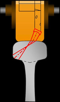
The transducers are housed in fluid-filled wheels mounted in a roller search unit carriage that couple the transducers to the rail (see Figure 2 below). A liquid couplant consisting of a thin film of water mixed with glycol or calcium facilitates the transmission of ultrasonic energy from the transducers into the rail. The transducers are set at different angles to achieve the best inspection coverage possible.
Appendix B – Rail Fatigue Defects Taber Subdivision
| Test date | Number of TDD/TDT | Rail weight | Year of manufacture |
|---|---|---|---|
| May 2006 | 1 | 115 | |
| August 2006 | 17 | 100/115 | 1954 – 1985 |
| December 2006 | 5 | 115 | 1955 – 1977 |
| February 2007 | 1 | 100 | 1950 |
| March 2007 | 3 | 100/115 | 1957 – 1975 |
| July 2007 | 11 | 100/115 | 1951 – 1979 |
| October 2007 | 8 | 115 | 1974 – 1983 |
| December 2007 | 15 | 100/115 | 1949 – 1979 |
| February 2008 | 10 | 100/115 | 1950 – 1979 |
| May 2008 | 15 | 115 | 1972 – 1979 |
| August 2008 | 10 | 115 | 1966 – 1979 |
| October 2008 | 8 | 115 | 1975 – 2004 |
| Derailment November 30 | |||
| December 2008 | 7 | 115 | 1971 – 1975 |
| January 2009 | 3 | 115 | 1974 – 1975 |
| April 2009 | 1 | 115 | 1991 |
| June 2009 | 0 | ||
| September 2009 | 4 | 115 | 1974 - 1979 |
Note: In addition, eight service TDD/TDT defects and 50 VSH/HSH defects were detected during this period.
- TDD: Transverse Detail Defect
- TDT: Transverse Defect Transverse Fissure
- VSH: Vertical Split Head
- HSH: Horizontal Split Head


