Non-main-track train runaway and collision
Kettle Falls International Railway
Waneta Turn Assignment
Mile 141.20, Kettle Falls Subdivision
Waneta, British Columbia
The Transportation Safety Board of Canada (TSB) investigated this occurrence for the purpose of advancing transportation safety. It is not the function of the Board to assign fault or determine civil or criminal liability. This report is not created for use in the context of legal, disciplinary or other proceedings. See Ownership and use of content. Masculine pronouns and position titles may be used to signify all genders to comply with the Canadian Transportation Accident Investigation and Safety Board Act (S.C. 1989, c. 3).
Summary
On 29 December 2008 at 1448 Pacific Standard Time, the Waneta Turn Assignment of the Kettle Falls International Railway ran uncontrolled down a steep grade near Waneta, British Columbia and collided with a cut of 25 stationary cars. Two locomotives and 12 cars derailed. The locomotive engineer received minor injuries. About 3000 gallons of fuel were spilled. Highway 22A was obstructed by the derailment for two days.
Ce rapport est également disponible en français.
Factual information
The accident
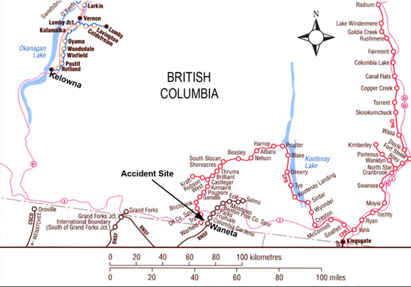
On 29 December 2008, at about 0700,Footnote 1 the crew of the Waneta turn assignment (the assignment), a locomotive engineer, a conductor, and a trainman, reported for duty at Kettle Falls, Washington, United States (U.S.), Mile 95.6 on the Kettle Falls Subdivision. The assignment proceeded northward from Kettle Falls to Mile 141.2, Waneta, British Columbia (see Figure 1), where twenty five cars comprising 10 loads and 15 empties were left on level track at the bottom of the steep grade up to Columbia Gardens, British Columbia, Mile 144.01.
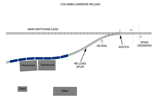
On the way to Columbia Gardens, switching was performed at Quirk Spur (Mile 142.7), where one loaded car of ammonium sulphate fertilizer was added to the train. The assignment arrived at Columbia Gardens with two locomotives, one covered hopper car loaded with fertilizer, and four empty boxcars. The assignment then coupled onto seven loaded boxcars of wood pulp that were in the reload spur (see Figure 2). The conductor had driven ahead of the assignment by truck, removed the derail, and lined the switch to the spur. The trainman, who was riding on the point of the movement, detrained and positioned himself at the switch to facilitate the assignment placing the loaded wood pulp cars on the adjacent track, the main switching lead.
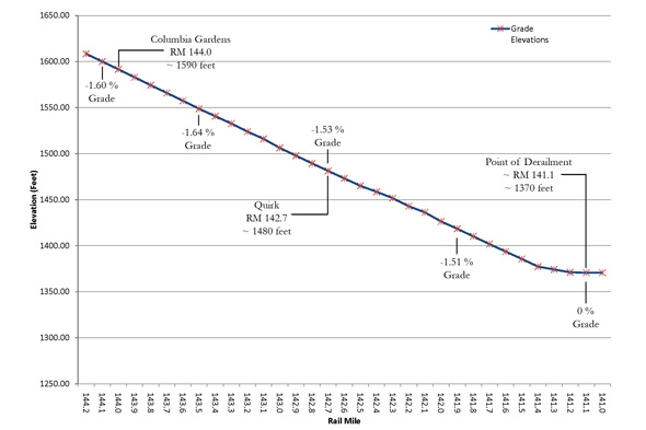
The assignment pulled forward. Once clear of the switch, it was unable to reduce speed and continued uncontrolled down the steep grade for a distance of 2.8 miles (see Figure 3), gradually accelerating to about 48 mph when it contacted the stationary cars.
Prior to the collision, the locomotive engineer initiated the process of changing the controlling locomotive from the lead to the trailing locomotive. This process was not completed before the locomotive engineer decided to detrain while traveling at about 20 mph. Due to the presence of a recent heavy snowfall, he received only minor injuries.
Just prior to the collision, a motorist was proceeding northbound on Highway 22A in a late model sport utility vehicle. Highway 22A is adjacent to the track on the west side. Anticipating the collision, the motorist accelerated and the side of his vehicle was struck by a small piece of debris from the collision. The motorist was uninjured.
At the time of the occurrence, there were snow flurries and the ambient temperature was −3°C.
Site examination
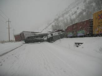
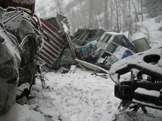
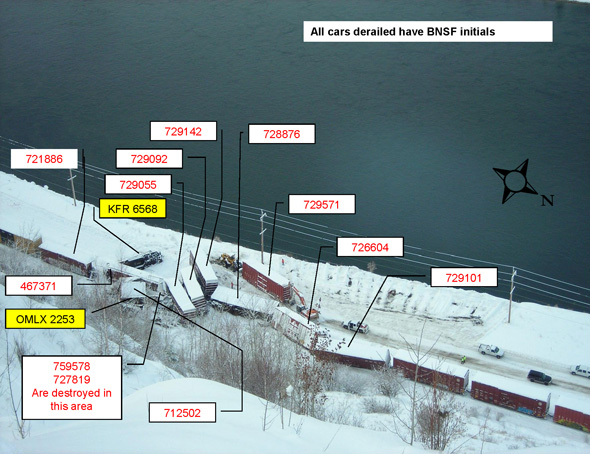
Two locomotives and 12 cars were derailed at Mile 141.20. The trailing locomotive and four of the cars came to rest on Highway 22A (see Photos 1, 2, and 3).
Lead locomotive OMLX 2253 came to rest east of the track, leaning at about 45 degrees to the left. Its fuel tank punctured and approximately 1450 gallons of fuel spilled. Trailing locomotive KFR 6568 was on its side. Its fuel tank detached, punctured, and about 1500 gallons of fuel spilled. From the assignment, one loaded hopper car containing ammonium sulphate fertilizer, four empty box cars, and three loaded boxcars containing wood pulp derailed. The last derailed box car remained upright and coupled to the remaining four loaded boxcars. All but one of the derailed cars were destroyed. From the cars left standing at the bottom of grade, the first four, all empty box cars, derailed and were also destroyed.
The spilled diesel fuel was contained by Teck Cominco's emergency response team, who responded soon after the accident. Their efforts prevented the fuel from entering the adjacent Columbia River. Some of the ammonium sulphate fertilizer spilled and was recovered. The remainder of the load was transferred to trucks. It posed no environmental hazard.
An examination of the last five cars of the train did not reveal any signs of excessive braking force on the wheels (for example, blueing, slid flats or built-up tread). The brake cylinder pistons were extended, indicating that the brakes were applied. All hand brakes were released. The angle cocks were in the open position, except for at the rear of the tail end car, which was closed. All retainers were in the direct exhaust position.
Three of the cars on the highway had been partially dismantled to facilitate reopening of the highway. Post-accident brake cylinder piston positions on these cars are unknown. The remaining cars were damaged to the extent that brake cylinder piston positions were unreliable. None of the wheel sets from these cars showed signs of heavy braking.
Examination of the locomotives revealed that:
- a traction motor was cut-out on the lead locomotive;
- the automatic brake valve handle was in the “handle off” position;
- the independent brake was cut out; and
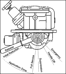
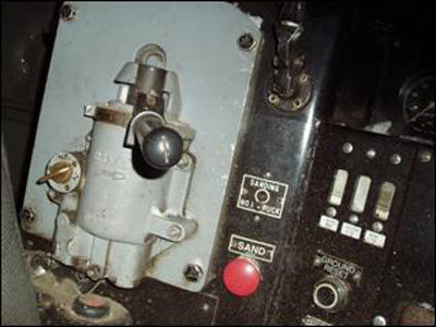
- the automatic brake valve cut-off valve was between the “in” and “out” positions (see Figure 4 and Photo 4).
Further examination of the other derailed rolling stock did not reveal any pre-derailment mechanical defects that would have affected their safe operation.
Locomotive event recorder
The locomotive event recorder (LER) information indicates that:
- In the 60 minutes prior to the occurrence, brake pipe pressure was reduced below equalization on at least six occasions.
- After coupling onto the seven loaded boxcars at 1401:46, the air brakes were charged from 1403:03 to 1405:34, about 2 ½ minutes.
- The air brakes were fully applied and the assignment began to move forward at 1406:09.
- At 1406:13, the independent (locomotive) brake was applied.
- At 1407:16, independent brake cylinder pressurization reached 75 pounds per square inch (psi), speed increased to 5 mph, and brake pipe pressure decreased below 60 psi.
- At 1407:25, brake pipe pressure dropped below 45 psi (to 44 psi).
- At 1407:26, the dynamic brakeFootnote 2 was set up and speed was 6 mph.
- Between 1407:26 and 1408:41, the dynamic brake was set up and released twice.
- At 1408:27, while travelling at 9 mph and with brake pipe pressure at 4 psi, an operator-initiated emergency brake application occurred.
- At 1408:41, the dynamic brake was released, locomotive brake cylinder pressure reached 85 psi, the reverser was placed into neutral, and train speed was 9 mph.
- At 1410:51, the train speed was 23 mph.
- At 1413:42, train speed was 48 mph and the train began to rapidly decelerate.
Crew information
The crewmembers met fitness and rest standards, were qualified for their respective positions, and were familiar with the territory. The conductor and the trainman each had four years of experience with the Kettle Falls International Railway (KFIR). All crewmembers had experience working this assignment.
The locomotive engineer had 30 years of experience, 4 years working with the KFIR. Between February 2005 and April 2005, he made three familiarization trips to Waneta. KFIR policy requires that locomotive engineers who received their initial training and certification while at other railways must make familiarization trips with a qualified KFIR locomotive engineer. As a previously certified locomotive engineer, he also received training in the following subjects:
- General Code of Operating Rules (GCOR);
- Safety;
- Hazardous Materials;
- FRA Part 232-Qualified person;
- Physical Characteristics of the Territory, and
- Canadian Rail Operating Rules (CROR 105 Territory).
The locomotive engineer was also subject to U.S. Federal Railroad Administration re-certification every three years that included:
- Federal Safety Rules;
- Mechanical;
- Air Brake and Train Handling; and
- General Code of Operating Rules
He was most recently re-certified on 02 September 2008.
Locomotive engineers participate in yearly knowledge and skills check rides with a Designated Supervisor of Locomotive Engineers. Additionally, locomotive engineers receive periodic rules compliance tests and observations in the work environment.
KFIR efficiency testing recordsFootnote 3 for the period between February 2007 and December 2008 showed that 65 tests were performed on the locomotive engineer, 71 tests on the conductor, and 64 tests on the trainman. “A majority of the efficiency testing produced positive results”. Those tests where a crewmember did not receive a passing result involved personal protective equipment or handling switches and derails. Out of the 65 locomotive engineer tests, however, only 15 per cent were related to train handling and brake system operation.
Track information
The Kettle Falls International Railway is a subsidiary of OmniTRAX, which owns and operates over 160 miles of former Burlington Northern Santa Fe track in northeastern Washington State and southeastern British Columbia. The Kettle Falls Subdivision is a single track subdivision that begins in Washington State, U.S., at Mile 60.5, station KFR/BNSF, and continues northward to Columbia Gardens at Mile 144.0. The international border is at Mile 139.9. North of the border, train movements are governed by Rule 105Footnote 4 of the Canadian Rail Operating Rules (CROR). The track is designated as non-main track.
The section of track between Mile 144.0 and Mile 141.0 descends to the south at a maximum grade of 1.66 per cent. In the area of the derailment, the track was comprised of 112-pound continuous welded rail laid on 12 and 13 inch double-shouldered tie plates and secured to softwood ties with four six-inch spikes per tie plate. The rail was box-anchored every third tie. The ballast consisted of crushed rock with 12 inch shoulders and was well-drained. The track was generally in good condition and was maintained in accordance with the Railway Track Safety Rules.
The switch for the reload spur is located at Mile 144.0. The spur extends approximately 700 feet from the switch to the reload facility. The first 200 feet is on a 1.4 per cent grade descending to the south. The remaining 500 feet is relatively level.
Operations and train handling
CROR Rule 105 requires that all movements operate at “reduced speed”. Reduced speed is defined as “a speed that will permit stopping within one half the range of vision of equipment”. In this occurrence, railway instructions had established a maximum operating speed of 20 mph and a permanent speed restriction of 10 mph between Mile 138.8 and Mile 140.41.
KFIR crews were trained on OmniTRAX Air Brake and Train Handling Rules and provided with a copy of these rules. These govern train operations on main track, non-main track, and yard track. They specify the following requirements (in part):
Grade Operation
Since train speed largely determines the amount of braking distance needed, control train speed in a grade operation as follows:
- Do not exceed the speed limit.
When conditions warrant, use all available braking power. If you are not sure that a service brake application will control the speed of the train, make an emergency brake application without hesitation.- Early in the braking process, achieve a balance between the level of dynamic brake and the level of air brake needed to control train speed on a descending grade.
- At speeds below 10 MPH, use extended range dynamic brakes if available. Extended range dynamic brakes provide more retarding force than locomotive brakes.
Balance Braking on a Grade
When a constant level of braking is required for long distances, do the following:
- Make a minimum brake pipe reduction and make further reductions of 2 psi until the train maintains the desired speed.
- Limit the effective brake pipe reduction to 15 psi or less. If a greater than 15 psi brake reduction is required to control train speed, stop train and inspect to determine reason before proceeding.
TSB laboratory report LP 003/2009
A simulation of the assignment's descent down the steep grade at Columbia Gardens was conducted using the occurrence train data, track data, and the data from the locomotive event recorder. It showed that the simulated descent that most closely matched the events recorded by the LER occurred when the cars experienced very little braking. The analysis concluded that not all air brake systems of the cars were sufficiently charged before the movement commenced, and that the air brake systems on some of the cars were below expected effectiveness at the time of the occurrence.
Switching operations at Columbia Gardens
The assignment departing Columbia Gardens consisted of two GP 38-3 2000 horsepower (hp) locomotives, one loaded covered hopper car, four empty box cars, and seven box cars loaded with wood pulp. It weighed approximately 1745 tons and was approximately 810 feet in length. In the recent past, three or four locomotives were used on this assignment and it would lift up to five loaded cars from the spur. Only occasionally would the assignment operate with two locomotives. On the day of the occurrence, seven loaded cars had been left in the spur as two cars remained from a preceding trip. All cars had been standing on the track for at least five days.
Air brakes
Air brakes on an individual car are activated or released through changes in the brake pipe air pressure, which was set at 88 psi for the occurrence train. The brake pipe is a continuous pipe through the train that acts as a conduit for air from the locomotive to supply and charge each car and as a signal line to deliver pneumatic commands for brakes to apply and release. The brakes can be applied in a “service” application or in an “emergency” application.
Service applications allow for the gradual increase in application culminating with a full service application. Service brake applications are achieved through the gradual reduction in brake pipe air pressure when the automatic brake valve is moved through the “application zone” (see Figure 4). The full service or fully applied position corresponds to an air brake concept called “equalization”. During full service application, air pressure in the auxiliary reservoirs and brake cylinders on the cars have equalized. Any further reduction in brake pipe pressure, at a controlled rate, will not result in a further increase in brake cylinder pressure on the cars.
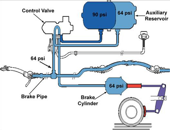
To reduce brake pipe pressure below equalization, the automatic brake handle must be moved beyond the application zone into “handle-off”. It was the locomotive engineer's belief that by reducing brake pipe pressure below equalization, additional locomotive brake cylinder pressure would be generated. Equalization for this train occurred when the brake pipe pressure was reduced to about 64 pounds per square inch (psi). Appendix A provides additional details on “equalization” on a standard freight car air brake system.
A rapid reduction in brake pipe air pressure will trigger an emergency brake application rather than a service brake application. Railway air brake control valve manufacturers do not recommend attempting to initiate an emergency brake application when the brake pipe air pressure is below 45 psi. In this situation, a reduced brake pipe air pressure may not successfully trigger the emergency brake application. A successful emergency brake application will increase brake cylinder pressures by about 12 per cent.
To ensure that brakes are operational, the individual air brake systems on each car must be fully charged (that is to say, the auxiliary and emergency reservoirs). Insufficiently charged air brake systems will not apply or will only partially apply. When cars are left standing in a yard or on a spur, the brake pipe is normally left open and brake pipe air pressure is vented to atmosphere. The auxiliary and emergency reservoirs remain pressurized, as do the brake cylinders if the cars were left with the brakes applied. However, over a period of a few days, the air will often leak out, leaving cars with unpressurized auxiliary and emergency reservoirs and with the brake cylinder pressure released. When the air brake system is fully depleted, fully charging a car can take six minutesFootnote 5 or more, depending on the brake pipe pressure setting and weather conditions.
Dynamic brake
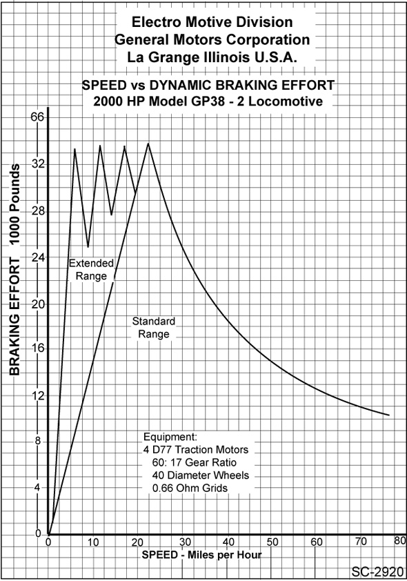
Both locomotives were equipped with dynamic brakes (DB). However, the dynamic brake on the lead locomotive was inoperative as a traction motor had been cut out. The second locomotive was equipped with extended range dynamic brake, which allows the dynamic brake to be effective at speeds below 10 mph. Dynamic brake reaches maximum effectiveness at about 20 mph (see Figure 5).
Neither locomotive was equipped with the dynamic brake holding feature, which prevents the dynamic brake from being inactivated during emergency brake applications.
Dynamic brake has been traditionally viewed as an additional (or back-up) braking system that is secondary to the train air brake system. Recent TSB investigations into runaway train events (for example, White Pass and Yukon (R06V0183), Lillooet (R06V0136), and Trail (R07V0109)) have highlighted the importance of effective, state-of-the-art dynamic brake systems in descending heavy grade territory.
In May and July of 2009, Transport Canada issued Ministerial Orders to all federally regulated railway companies with respect to the Railway Locomotive Inspection and Safety Rules and the Railway Freight and Passenger Train Brake Inspection and Safety Rules, respectively. These orders directed the railways to formulate specific rules requiring dynamic braking on locomotives in certain geographical areas and to ensure locomotives presently equipped with dynamic braking are modified to have the dynamic brake holding feature added. The deadline month for submitting the proposed revisions to the Minister was February 2010. On 04 February 2010, Transport Canada approved revisions to the Railway Locomotive Inspection and Safety Rules. On 05 May 2010, Transport Canada approved revisions to the Railway Freight and Passenger Train Brake Inspection and Safety Rules.
Analysis
The investigation determined that the assignment ran uncontrolled down the steep grade at Columbia Gardens and collided with cars left standing on the track at Waneta. The analysis will focus on the reasons why the assignment became uncontrolled and the actions taken by the locomotive engineer to regain control.
The accident
The locomotives and cars were in serviceable condition. A full service brake was applied on the cars before the assignment commenced its southward movement out of the reload spur. However, the braking force generated was insufficient, allowing the assignment to travel past the switch and down the steep grade.
The seven loaded cars on the reload spur had been stationary for a number of days without being connected to a locomotive air supply. Given the time that had elapsed since they were last charged and the cold weather conditions, it is unlikely that these cars would have retained much air pressure in their brake systems when they were coupled on the day of the accident. The total time necessary to fully charge these cars would have been at least six minutes and most likely longer due to the cold temperature conditions and the brake pipe pressure setting. The two and a half minutes that the seven loaded boxcars were charged before the movement commenced was not long enough to ensure that the brake systems on those cars were fully operational. Therefore, the assignment began its southward movement onto the steep descending grade with insufficiently charged brakes.
In addition to an underperforming train brake, the two locomotives supplied less braking force from the independent brakes than was usual (normally there are three or four locomotives for this assignment). Because more cars (and hence additional weight) had been placed on the assignment than usual, the braking force required was also higher than usual. Although the locomotive engineer had experience working in this territory, it is likely that he underestimated the effect of the additional tonnage and the reduced braking capacity when he pulled onto the steep grade with the assignment less than fully charged.
When the assignment failed to respond to efforts to stop, the locomotive engineer reduced the brake pipe pressure below equalization. This action compromised the ability to achieve an emergency brake application throughout the assignment.
In preparation for a change in control from the lead locomotive to the trailing locomotive, the locomotive engineer cut out the dynamic brake along with the automatic and independent brake valves.Footnote 6 Up until that point, the assignment had accelerated gradually, increasing speed by 8 mph over 2 minutes and 35 seconds. However, after the DB was cut out, the assignment accelerated much more rapidly (that is to say, increasing speed by 14 mph over the next 2 minutes and 9 seconds and by 25 mph over the remaining 2 minutes and 51 seconds) until the collision. Because brake force for extended-range DB increases as speed increases above 5 to 7 mph, the DB on the trailing locomotive would have produced more braking effort as the assignment accelerated, at least until a speed of about 20 mph. The aborted attempt to change controlling locomotives eliminated most of the braking effort that was being generated and increased the severity of the collision.
Handling train movements on long, steep grades
The locomotive engineer was aware that the assignment was not fully charged as he elected to apply a full service brake application before pulling southward to clear the switch. However, it was not the intention of the crew to descend the grade at this time because switching activities had not yet been completed. Railway instructions for descending grades with a train require a much more judicious use of air brake capacity (that is to say, maximum brake pipe reduction of 15 psi followed immediately by emergency if the movement cannot be controlled). However, these instructions do not address the risks involved when switching on track with significant grades. For example, there were no instructions requiring crews to fully charge the cars air brake systems or to perform an air brake test prior to travelling onto a steep grade. Consequently, when addressing the braking requirements of a switching assignment, locomotive engineers are required to use their training, experience, and best judgement. However, when presented with situations such as handling additional cars with fewer locomotives than they are used to, locomotive engineers may not always take steps that fully mitigate the risks. When railway operating instructions do not provide guidance on safe switching practices during the handling of train movements on long steep grades, there is an increased risk of runaways, leading to derailments or collisions.
Locomotives with inoperative dynamic brakes
The lead locomotive had a traction motor cut out, rendering its dynamic brake inoperable. Recent TSB investigations have highlighted the importance of effective, state-of-the-art dynamic brake systems in heavy grade territory. When locomotives with inoperative dynamic brakes continue in active service in heavy grade territory, an important tool for train control is not available, increasing the risk of a runaway event.
Reducing brake pipe pressure below equalization
The practice of reducing brake pipe pressure below equalization to achieve additional brake force has been a misconception known to air brake specialists for many years. Extensive railway industry training has minimized the extent of this practice. By reducing the brake pipe pressure below equalization, an unapproved adaptation to safe railway air brake practices was used, compromising the ability to control the assignment. Despite being qualified, experienced, and supervised regularly, the locomotive engineer did not fully understand the effects of reducing brake pipe pressure below equalization.
The following TSB Laboratory report was completed:
LP 003/2009 – LER Data Analysis
This report is available from the Transportation Safety Board of Canada upon request.
Findings
Findings as to causes and contributing factors
- The accident occurred when the assignment ran uncontrolled down the steep grade at Columbia Gardens, British Columbia, and collided with cars left standing on the track at Waneta, British Columbia.
- Although brakes had been applied prior to beginning to travel southward toward the reload spur switch, the braking force generated was insufficient.
- The assignment began its southbound movement onto the steep descending grade with insufficiently charged brakes.
- Although the locomotive engineer was experienced working this territory, it is likely that he underestimated the effect of the additional tonnage and the reduced braking capacity when he pulled onto the steep grade with the assignment less than fully charged.
- There was a misconception about generating additional braking force and, during the uncontrolled descent, brake pipe pressure was reduced below equalization, compromising the ability of the assignment to achieve an emergency brake application.
- The aborted attempt to change controlling locomotives eliminated most of the braking effort that was being generated and increased the severity of the collision.
Findings as to risks
- When railway operating instructions do not provide guidance on safe switching practices during the handling of train movements on long steep grades, there is an increased risk of runaways, leading to derailments or collisions.
- When locomotives with inoperative dynamic brakes continue in active service in heavy grade territory, an important tool for train control is not available, increasing the risk of a runaway event.
Other finding
- Despite being qualified, experienced, and supervised regularly, the locomotive engineer did not fully understand the effects of reducing brake pipe pressure below equalization.
Safety action taken
Transport Canada
Subsequent to the accident, Transport Canada performed a regulatory inspection. This inspection led to the issuance of a Notice and a Notice and Order under Section 31 of the Railway Safety Act on 12 January 2009.
The Notice stated:
Hazard or Condition
Operation of movements on grade without a complete understanding of the operation of the air brake system and the functionality of locomotive control features may result in experiencing an uncontrolled movement with serious consequences resulting in derailment and injury to persons, damage to property and the environment.
The Notice and Order stated:
Hazard or Condition
The lack of clear train handling instructions related to switching and descending the grade between Mile 145.0 and Mile 142.0 Kettle Falls subdivision can lead to operating crews descending this grade with less than adequate air and operative brakes to properly control their movement, resulting in the risk of an uncontrolled movement, creating a threat to the public, employees and the environment.
I therefore order that;
OmniTRAX must not allow movements to descend the grade between Mile 145.0 and Mile 142.0 on the Kettle Falls subdivision unless the following conditions are met;
- That all movements receive the equivalent of a number 1A air test prior to any descent,
- That prior to any descent, a sufficient amount of time is permitted for charging the equipment to be handled to ensure a safe descent,
- That a calibrated air gauge or sense and braking unit (SBU) is utilized to assist the operating crews,
- Any other means that are available are utilized as required to ensure a safe descent.
Kettle Falls International Railway
In January 2009, Kettle Falls International Railway (KFIR) issued General Order No. 09-18, which requires that:
Crews working at any industries between MP 145 and MP 142 on the Kettle Falls Subdivision must ensure that all cars pulled from industries onto the main switching lead have received a Class 1 air brake test as prescribed in Air brake and Train Handling Rules 100.10.
After the cut of cars have been tested as prescribed, they may then be pulled onto the main switching lead and properly secured until all industries in the area have been switched and all of the cars for the outbound train have been assembled.
Before departing, conduct an Application and Release Test (Class 3 Air Brake Test) ABTH 100.15.
Other safety action initiated by KFIR includes:
- All crews were briefed on the derailment and the known causes with special attention to the proper use of the air brake systems.
- All crews on KFIR received additional training covering the following:
- The events leading up to and causing the derailment, including a thorough discussion of the down load.
- Instruction and discussion on train handling, including the use of automatic and dynamic brakes to control movement.
- Train air brake operation including charging time and instigation and effects of emergency brake applications.
- Locomotive operations including the use and capability of dynamic brakes and the effects of combined use of dynamic and independent brakes.
- Instruction and discussion was held on the KFIR General Order No. 09-18.
This report concludes the Transportation Safety Board's investigation into this occurrence. Consequently, the Board authorized the release of this report on .
Appendices
Appendix A – Equalization on a standard freight car air brake system
Note that brake cylinder pressure and auxiliary reservoir pressure have equalized at 64 pounds per square inch (psi). A further reduction in brake pipe pressure (the pneumatic signal) will not result in any further increase in brake cylinder pressure.
