Main-track derailment
Canadian National Railway
Freight train M30141-20
Mile 149.21, Wainwright Subdivision
Fabyan, Alberta
The Transportation Safety Board of Canada (TSB) investigated this occurrence for the purpose of advancing transportation safety. It is not the function of the Board to assign fault or determine civil or criminal liability. This report is not created for use in the context of legal, disciplinary or other proceedings. See Ownership and use of content. Masculine pronouns and position titles may be used to signify all genders to comply with the Canadian Transportation Accident Investigation and Safety Board Act (S.C. 1989, c. 3).
Summary
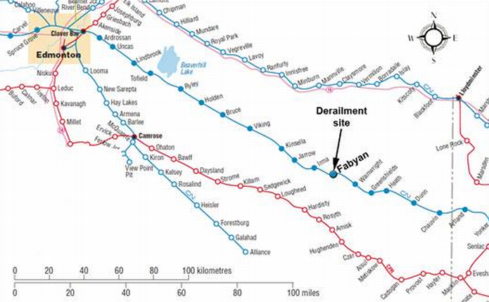
On 21 January 2012, at 1617 Mountain Standard Time, Canadian National Railway freight train M30141-20, proceeding westward from Wainwright, Alberta, to Edmonton, Alberta, derailed 31 cars at the east end of Fabyan Bridge (Mile 149.21) on the Wainwright Subdivision, near Fabyan, Alberta. The derailed cars were loaded with grain, and 17 of these cars fell off the north side of the bridge, damaging several steel tower legs and bracing members. Approximately 1760 feet of track was destroyed. There were no injuries.
Ce rapport est également disponible en français.
Factual information
On 21 January 2012, at about 1600, Footnote 1 Canadian National Railway (CN) freight train M30141-20 (the train) departed Wainwright, Alberta (Mile 140.0), of the Wainwright Subdivision destined for Edmonton, Alberta (Mile 263.3). The conventional train was powered by 2 locomotives: CN 5734, an EMD SD75i, 6-axle locomotive generating 4300 horsepower (hp) and CN 2156, a GE Dash 8-40CW, 6-axle locomotive generating 4135 hp. Both locomotives were equipped with extended range dynamic brake (DB). The locomotives were pulling 137 cars, including 87 loads, 19 empties and 31 residue cars. The train weighed 12 724 tons and was 8228 feet long.
The train originated in Winnipeg’s Symington Yard on 20 January 2012, where a No. 1 air brake test was performed. Footnote 2 In Saskatoon, Saskatchewan, on 21 January 2012, 74 loaded cars of grain were picked up, and the train was brake tested and inspected. The train was further inspected en route by the hot box and dragging equipment detectors (HBDs) at Dunn (Mile 119.4) and Greenshields (Mile 132.5) before reaching Wainwright. No defects were noted.
Shortly after leaving Wainwright, the train crested the grade at Mile 143.5 and began the descent towards Fabyan Bridge (Figure 1). DB was used to control train speed while descending the 0.4% grade. Train speed was maintained at 38 mph as it approached the 40 mph permanent slow order between Mile 147.5 and Mile 150.2. There is a 4° right-hand curve in the track just before the east approach to Fabyan Bridge. At this location, the track gradient for westward trains changes from descending to ascending (that is, apex of a vertical depression in the track).
DB was released at 1616:18, and the throttle was placed in idle just as the head end of the train reached the bridge and began to ascend. The transition between DB and throttle was smooth, and no "tug" or unusual resistance was reported. The throttle was placed in position 1 at 1616:27 and was increased to maximum (position 8) over the next 38 seconds. While the train was travelling at 41 mph, a train-initiated emergency brake application occurred at 1617:09. The crew looked back and observed derailed cars falling off the bridge. The locomotives and part of the train continued across the bridge and stopped at 1617:41.
After making the necessary emergency broadcast and notifying the rail traffic controller (RTC), the locomotive engineer and conductor walked back onto the bridge to assess the situation. Thirty-one loaded grain cars had derailed (35th to 65th cars). Seventeen of the derailed cars had fallen off the north side of the bridge. There were no injuries.
The weather at the time of the accident was -25°C and mainly clear.
Subdivision information
The Wainwright Subdivision is part of CN’s transcontinental mainline route that extends from Biggar, Saskatchewan (Mile 0.0), to North Edmonton (Mile 264.7). Train movements are governed by the Centralized Traffic Control System (CTC), as authorized by the Canadian Rail Operating Rules (CROR), and supervised by an RTC located in Edmonton. The permissible freight speed in this area is 40 mph, making it a Class 3 track as defined in the Railway Track Safety Rules.
Crew information
The crew, consisting of a locomotive engineer, a student locomotive engineer and a conductor, took control of the train at Wainwright. The crew members were qualified for their respective positions and met company and regulatory fitness and rest standards. The student locomotive engineer, who was at the controls of the train, was familiar with the Wainwright Subdivision and with the train-handling requirements approaching Fabyan Bridge. He had worked on this subdivision approximately 10 times.
Site examination
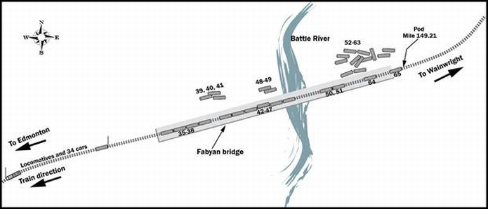
Of the 31 derailed cars, 13 remained on the bridge (Figure 2). The first 4 derailed cars on the bridge were the 35th to the 38th cars:
- The “B” end of the 35th car was oriented to the west. Footnote 3 The L1 and R1 wheels were on the rail. The R2, R3 and R4 wheels were derailed to the south of the south rail. The L2, L3 and L4 wheels were derailed to the centre of the track, between the north rail and the guard rail.
- The “B” end of the 36th car was oriented to the west. The R1, R2, R3 and R4 wheels were derailed to the south of the south rail. The L1, L2, L3 and L4 wheels were derailed to the centre of the track, between the north running rail and the guard rail.
- The 37th car was derailed upright on the bridge with its north wheels derailed to the north of the north rail, and the south wheels derailed into gauge between the south rail and the guard rail.
- The 38th car was derailed upright on the bridge with its north wheels derailed to the north of the north rail, and the south wheels derailed into gauge between the south rail and the guard rail.
All other derailed cars that remained on the bridge derailed in the same manner as the 37th and 38th cars. Table 1 provides a summary of the location of the derailed cars.
| Car position | Derailed on the bridge | Fell off the bridge | Derailed upright on the east bridge abutment |
|---|---|---|---|
| 35th to 38th | 4 | - | - |
| 39th to 41st | - | 3 | - |
| 42nd to 47th | 6 | - | - |
| 48th and 49th | - | 2 | - |
| 50th and 51st | 2 | - | - |
| 52nd to 63rd | - | 12 | - |
| 64th | 1 | - | - |
| 65th | - | - | 1 |
| Total derailed cars | 13 | 17 | 1 |
An examination of the 4° curve at the east end of the bridge revealed:
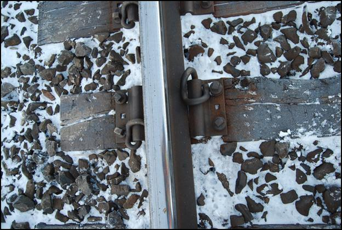
- Lag screw fasteners had been pulled out of a number of ties on the high rail (Photo 1).
- The high rail had rolled over at this location.
- Wheel marks observed on the flange and web of the high rail indicate that the point of derailment (POD) was approximately 67 feet east of the east bridge abutment (Photo 1).
- Plate-cut ties Footnote 4 were observed, along with many missing and broken screws, as well as bent and broken plates.
- Some clips were missing, and not all fastener holes appeared to be filled where the rail was not rolled.
- Many “missing” lag screws had broken off in the ties.
- There were some cracked and broken tie plates.
Seventy-four broken and damaged lag screws were collected and sent to the TSB Laboratory for analysis (Photo 2).
Approximately 1760 feet of track was destroyed during the accident (Photo 3). There was also damage to various components of the bridge, which included the north top section of the east wing wall that detached and fell to the ground; walkway gratings; north side concrete curbs between spans 2 and 31; north tower legs and bracing of bents 1, 2, 5, 15 and 16; bent stiffeners on the north girders of spans 5, 6 and 8; and various other structural members.
Track and bridge restoration
Track restoration required the installation of 45 new track panels. Bridge repairs took longer than the track restoration work. During the repairs, rail traffic was rerouted over CN's Prairie North Line. The track was reopened on 26 January 2012, 5 days after the occurrence.
Track information
The derailment occurred at Mile 149.2, which is located in a 4° right-hand curve at the east approach to Fabyan Bridge. The curve had an average of 3.6 inches of superelevation, which was balanced for the 40 mph posted track speed. The rail through the curve was 2002 NKK 136-pound fully head-hardened (FHH) continuous welded rail (CWR). Within the curve, the rail was secured onto 16–inch rolled tie plates with elastic fasteners. The tie plates were attached to hardwood ties with 4 screws per plate (Photo 4). The rail was box-anchored every tie. The ballast was crushed rock in good condition. The elastic fastening system was originally installed in 1997 on a mix of softwood and hardwood ties. In 2004, the remaining softwood ties were replaced with hardwood ties. Elastic fasteners were used up to the east end of the bridge.
The track across the bridge was comprised of 136-pound rail on 16-inch double-shouldered tie plates fastened to hardwood ties with 6 spikes per plate. The rail was box-anchored every tie. The ballast was crushed rock in good condition.
Bridge guard rails, which are designed to keep derailed wheels centered on the bridge structure and to prevent cars from falling off, had been installed on Fabyan Bridge. The guard rails were 115-pound jointed rail with 6-hole splice bars and spiked every second tie. The guard rails had been installed between the running rails, 14 inches from the south rail and 11.5 inches from the north rail. CN's standard plan TS 1108 (Typical Guard Rail Installation) specifies a distance of 11 inches from the rail for open deck bridges with bridge plates.
Bridge information
Fabyan Bridge is a 2869-foot-long viaduct that spans the Battle River Valley and is a key structure in CN's mainline route (Photo 5). It has a maximum height of 190 feet. The bridge consists of:
- two 23-foot-long ballast deck prestressed concrete girder (PCG) spans;
- two 26-foot-long ballast deck PCG spans built in 1972;
- fifty-two 50-foot-long deck plate girder (DPG) spans; and
- one 152-foot-long deck truss (DT) span built in 1908.
In 1984, a concrete ballast deck replaced the open deck on the DPG and DT spans. The bridge spans are supported on steel lattice-braced towers.
Track inspection and maintenance
Prior to the occurrence, the track was inspected by hi-rail on 15 January, 16 January, 17 January and 18 January 2012. The bridge was inspected on 19 January 2012. No exceptions in the vicinity of the derailment were noted during these inspections.
Walking inspections were conducted on the 4° right-hand curve in March 2011 and October 2011. It was noted that loose screws had been turned down and broken screws had been replaced. Within the curve, approximately 20 lag screws had been replaced in the past 3 years. Footnote 5
The rail had been ultrasonically tested 15 times in 2011; the last test prior to the derailment was conducted on 29 December 2011. During these tests, no rail defects were detected near the POD. In 2011, 7 track geometry tests were conducted using CN's TEST car. Footnote 6 The TEST car results include:
- A number of near-urgent wide gauge defects (up to 1⅛ inch wide for Class 3 track) were detected in the 28 July, 17 August and 25 October tests.
- Ongoing gauge widening was occurring throughout the curve.
- A comparison of the 29 March and 25 October geometry tests indicated that gauge had increased from 0.2 inches to 0.4 inches in 3 locations over approximately 95 feet near Mile 149.1.
- A comparison of the 14 September 2010 and 25 October 2011 tests revealed a small increase in rail cant on both rails in the vicinity of the POD.
Mechanical inspection of first derailed cars
Mechanical records for the first 2 derailed cars, CN 395562 (35th car) and IC 799666 (36th car), were reviewed. No exceptions were noted. A teardown inspection of both of these hopper cars was conducted. No defects were noted, and there was no evidence of truck binding or fouling on the side bearings or centre plate of these cars.
Track/train dynamic analysis
A Train Operations and Energy Simulator (TOES) simulation was conducted by CN and verified by the TSB. This analysis was used to estimate the in-train forces. It was determined that, just prior to the occurrence, the maximum draft force was 70 000 pounds and the maximum buff force was 40 000 pounds. The magnitude of these forces would be considered normal for this type of train operation.
Track fastening systems
Track components respond and interact with each other when subjected to train-wheel loads. Train loads are transferred from the rail into the subgrade through the fasteners, tie plates, ties, ballast and sub-ballast.
In conventional fastening systems, track spikes serve the dual role of positioning the rail in the tie plate and securing the tie plate to the tie to maintain gauge. In heavy-axle-traffic territory on curved track with conventional fastening systems, spikes can become loose over time due to wheel loading and can work their way out of the tie. In these situations, the spike holes become enlarged, resulting in wide gauge. The interior of the tie will then be exposed to moisture, which can lead to tie decay.
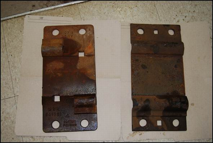
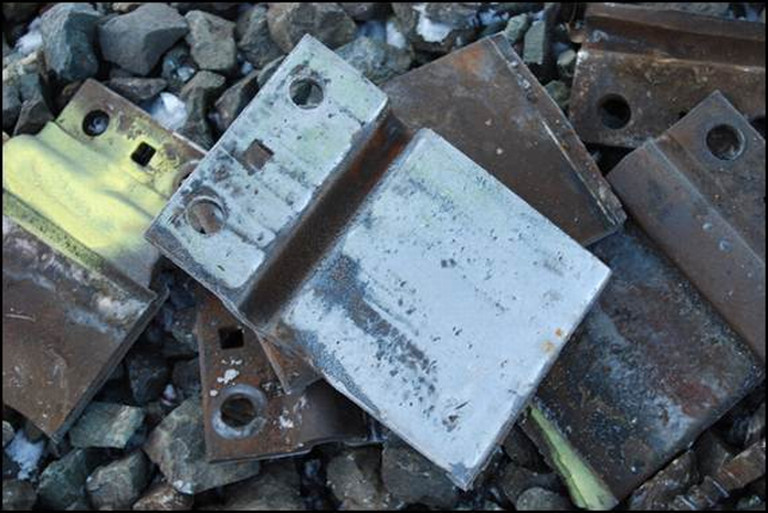
In contrast to the conventional fastening system, cast-plate and rolled-plate fastening systems (Photo 6) provide the 2 separate fastener functions. The rail is attached to the tie plate with an elastic fastener, normally an “e”-shaped round heat-treated steel bar (20 millimetres in diameter). The tie plate is then attached to the tie with lag screws or a combination of screws and spikes. The cast ductile iron tie plate has wedge-shaped lugs in the bottom that embed in the wood tie to add extra holding power. Rolled plates have smooth bottoms without lugs (Photo 7).
Elastic fastening systems provide a much stronger track structure that is more resistant to high lateral and longitudinal forces and to the development of wide gauge and rail cant. The screw fasteners provide increased resistance to tie-plate movement, thereby increasing gauge-widening strength and the gauge-widening life of the track. Rail hold-down strength and resistance to rail roll-over is also increased.
When elastic fasteners are used, during rail change-outs, the fasteners are simply removed and reapplied with no loss of hold-down strength. Although it is a much more robust fastening system, failure of the lag screws can occur over time. Normally, lag screw failure is due to a combination of shear and bending stress, as lag screws do not necessarily receive even loading.
In this occurrence, 2 types of screws were used in the curve: the original Ss5 – 7½ -inch screws and the Ss5 – 8½ -inch screws. These lag screws are “2 pitch” Footnote 7 screws that are installed with a spring washer. The use of newer, shorter 6½ -inch “3 pitch” screws that do not use a spring washer is the current industry standard. The longer screws and washers were originally thought to provide more resilience to the fastening system. However, the “3 pitch” screw provides more holding power and is easier to install.
TSB Laboratory Report LP 025/2011 – Lag Screw Analysis
The 74 failed lag screws submitted for examination were produced from 4 different batches and supplied by 3 different manufacturers. The presence of several batches and manufacturers was due to the ongoing replacement of broken screws with newer stocks. The laboratory analysis determined that:
- The strength of the lag screw steel met specifications in effect at the time of manufacture.
- The fatigue cracks in the lag screw started in the upper portion of the threaded shanks.
- There were multiple fatigue origins, suggesting that fatigue initiation was caused by a general stress condition rather than any material defect.
- The age of fatigue cracks in different screws varied from many years to shortly before the occurrence.
Analysis
Neither the condition of the rolling stock nor the manner in which the train was operated was considered contributory to this accident. Because the high rail in the derailment curve appeared to roll over, the analysis will focus on the track fastening system through the derailment curve.
The accident
The curve in which the POD is situated is the apex of a vertical depression in the track. Consequently, this location coincides with a significant train-handling transition for both westward and eastward trains. The recommended train-handling practice is to use dynamic brake when descending into the bottom of a depression and to use power (i.e., increase throttle) to pull up on the other side. While these instructions are entirely appropriate to the terrain, additional dynamic forces will routinely be exerted against the rail. In this occurrence, this location was a point of vulnerability, and the effect of normal dynamic forces from train operations on the track structure was recognized. In 1997, elastic fasteners and rolled tie plates were installed in the curve.
If the screws are tight on the rolled plates, the clamping force produces friction between the plate and the tie, providing lateral resistance to gauge-widening forces in the curve. If the screws are loose, they act as pins, providing the sole lateral resistance. When this happens, the flat bottom rolled plates move under load and can break (Photo 8). Failure of the screws is usually due to a combination of shear and bending, as all screws do not receive even loading.
In this occurrence, a number of lag screws in the vicinity of the POD broke off in the tie. The breaks, which occurred over a considerable period of time, were due to fatigue at the transition point between the shank and the threads, where the cross-sectional area is reduced. Even with broken lag screws, there was little indication that the curve was under stress, as track gauge was maintained by the lag screws that did not break. The remaining intact lag screws experienced much higher lateral curving forces. The derailment occurred when the remaining screw fasteners were insufficient to resist the lateral curving forces; the high rail then rolled under the train, resulting in wheels falling into gauge at the east end of Fabyan Bridge.
Signs of wide gauge are normally more apparent in curves with conventional spike fasteners. If a track with conventional fastenings is under excessive lateral stress, the rail will cant, spikes will rise and stay up, and plate cutting on the field side will be more pronounced. These conditions would likely be noted during routine track inspections.
In this occurrence, the TEST car located some localized near-urgent wide gauge track defects. Comparison of TEST car pengraphs indicated that there was a small increase in track gauge and rail cant in the curve. During routine track inspection, broken and lifted lag screws, plate cutting, and bent and broken plates were observed. While the odd broken lag screw was replaced and lag screws that had worked their way out were turned down, additional maintenance action to secure the curve was not initiated. When signs of dynamic wide gauge in a curve are difficult to detect or are not acted upon, components in the rail fastening system may progressively fail, increasing the risk of rail rollover and derailment.
Bridge guard rails
Bridge guard rails are designed to keep derailed wheels centered on the bridge structure and to prevent cars from falling off and damaging the bridge or what lies below. Although reasonably effective on tangent track, bridge guard rails are less effective in curves and in situations where the train is partly in the curve. In this occurrence, as the train travelled through the curve and reached the tangent track on the bridge, the cars that had derailed due to the rail rollover were effectively dragged to the north side of the bridge where they fell off. With the derailment occurring on the curve at the east end of the bridge, the bridge guard rails could not prevent all of the derailed cars from falling off the bridge.
Findings
Findings as to causes and contributing factors
- The derailment occurred when the high rail rolled over in the curve at the east end of Fabyan Bridge.
- The progressive failure of a number of lag screws in the rail fastening system resulted in an insufficient number of remaining lag screws to resist the lateral curving forces of the train.
- Frequent inspections and observation of conditions did not indicate that the curve was under stress, and action was not taken to adequately secure the curve.
Finding as to risk
- When signs of dynamic wide gauge in a curve are difficult to detect or are not acted upon, components of the rail fastening system may progressively fail, increasing the risk of rail rollover and derailment.
Other findings
- At the apex of a vertical depression in the track, normal train action will result in additional dynamic forces on the track structure.
- With the derailment occurring on the curve at the east end of the bridge, the bridge guard rails could not prevent all of the derailed cars from falling off the bridge.
Safety action
Canadian National
On 23 January 2012, CN implemented the following “Guidelines for Inspections of Curves, Turnouts, and Bridge Decks with Screw Spikes”:
When conducting inspections of curves, turnouts, and bridge decks with screw spikes, please be governed by the following:
- Walk the entire curve inspecting both the high rail and low rail.
- Look for signs of plate movement.
- Use the geometry car printouts to identify areas of concern. Inspect all areas where the test car reports show a combination of wide gauge and alignment defects on either rail.
- Observe the washer head and look for shiny marks on the plate as evidence of possible broken screw spikes.
- Take a steel rod (lining bar) and strike every tie plate, noting any loose or bouncing screw spikes, which would indicate breakage.
- Hand inspect every 10th tie by physically attempting to pull on all the screw spikes on that plate to see if they can be pulled out of the tie by hand.
- At transition areas (wood ties territory going from cut spike to screw spikes and wood ties territory with screw spikes going to concrete ties) hand inspect every tie on both rails for 10 ties beyond the transition point.
- Additional inspection of screw spikes will be required, by unscrewing them from the tie. The Inspection intervals will be as follows:
- curves 1/2 degree to 6 degrees - Every 100 feet on the high rail remove the screw spike from the tie and inspect. At a 50 foot offset from the high rail, remove and inspect the screw spikes every 100 feet on the low rail as well.
- above 6 degrees curves - Every 50 feet on the high rail remove the screw spike from the tie and inspect. At a 25 foot offset from the high rail, remove and inspect the screw spikes every 50 feet on the low rail as well.
- Once the screw spike has been removed from the tie inspect it for cracks and other obvious signs of wear.
- Observe the unthreaded area of the screw spike. If this area shows 1/8″ reduction in diameter continue to monitor the curve closely. If the area shows 1/4″ reduction in diameter, the screw spikes should be incorporated into a planned program for replacement.
- When a broken screw spike is found, check the surrounding area to determine the extent of the broken screw spikes.
- Areas where ballast has been left over the plates should be cleared to enable inspection of the screw spikes.
- Limit operating speeds over areas of concern until repairs can be made.Footnote 8
For some curves, CN is specifying the use of a new, superior type of tie plate with wood tie elastic fastener systems. The tie plates are 7½ inches by 18 inches cast ductile, each fastened to the ties with 4 screws and 2 spikes. The rails will continue to be fastened to the plate using “e”-type elastic fastener clips. The tie plates are more robust and resistant to breakage than the rolled plate. Lugs on the bottom of the tie plate will dig into the tie, providing mechanical resistance and friction resistance to lateral curving forces.
This report concludes the Transportation Safety Board's investigation into this occurrence. Consequently, the Board authorized the release of this report on . It was officially released on 25 October 2012.
