Table of contents
1.0 Introduction
1.1
On 06 July 2013, a Montreal, Maine & Atlantic Railway (MMA) freight train consisting of 5 locomotives, a Van Buren car (caboose converted to hold remote-control operation equipment), a loaded box car filed with gravel (buffer car) and 72 tank cars loaded with petroleum crude oil travelled un-manned from Nantes to Lac-Mégantic, Quebec, where 63 of the tank cars and the 1 box car derailed. Numerous tank cars ruptured, and a fire ensued.
1.2
During the field investigation, a feature was observed on a wheel flange of the number 3 wheel set from the box car (CIBX 172032). The wheel set was sent to the Transportation Safety Board (TSB) Engineering Laboratory to determine the possible cause of the feature.
2.0 Examination
2.1
Tables 1, 2 and 3 show the markings that were observed on the wheel hubs, axle locking plates, and the outer race of bearings.
| Wheel with feature | Mating wheel | Marking significance |
|---|---|---|
| 83414 | 80228 | Wheel serial number |
| 05 98 | 05 98 | Date of manufacture |
| CH36 | CH36 | 1 wear, 100 t on maximum capacity per wheel, 36 inch diameter wheel, cast, wide flange wheel |
| C | C | Class C wheel (heat treated rim) |
| GC | GC | Manufactured by Griffin Wheel, Columbus, Ohio |
| 7 TILX98G | Wheel mounted by Trinity Industries, Greenville, PA, July 1998 |
| Wheel with feature | Mating wheel | Marking significance |
|---|---|---|
| TILX-G | TILX-G | Bearing mounted by Trinity Industries, Greenville, PA |
| ND98 | NE98 | Bearing mounted new in 1998, D – April, E - May |
| Wheel with feature | Mating wheel | Marking significance |
|---|---|---|
| Brenco HM133416XD USA | Brenco HM133416XD USA | Name of manufacturer, bearing model number, country |
| D 98 | E 98 | Date of manufacture, D – April, E – May |
| 67160 | 69378 | Bearing serial number |
2.2
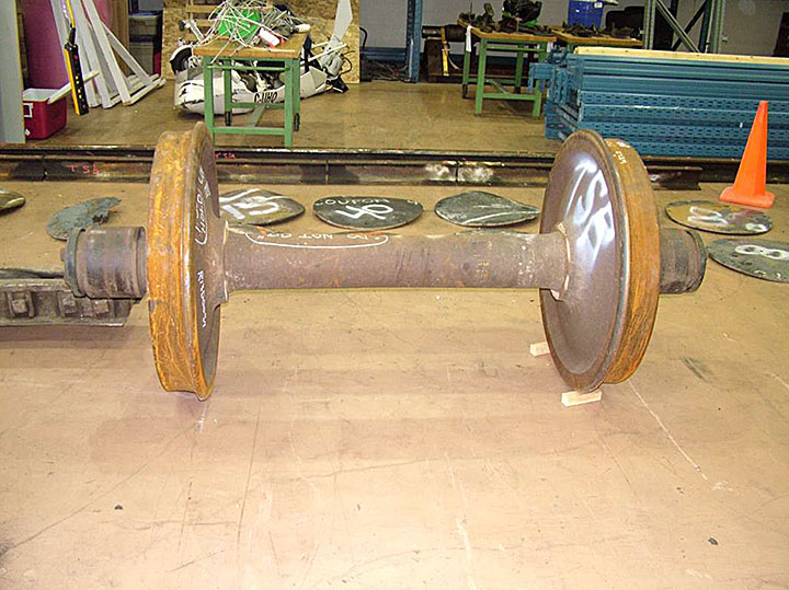
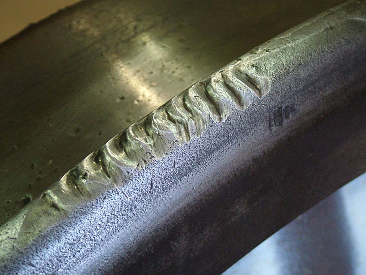
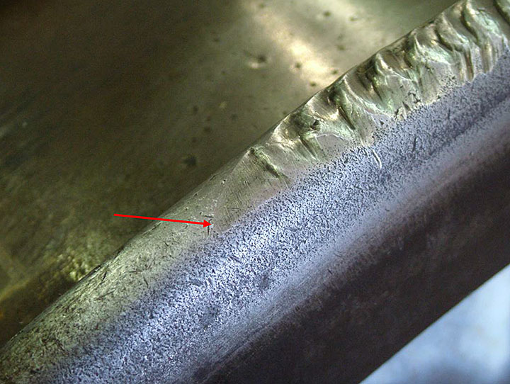
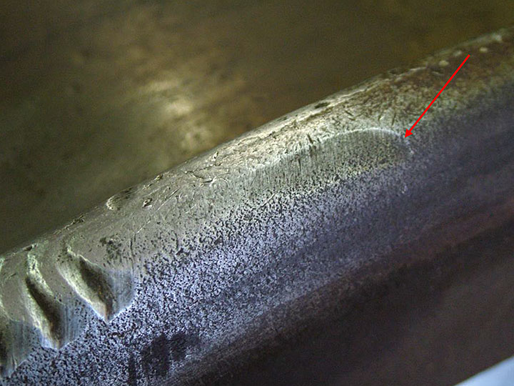
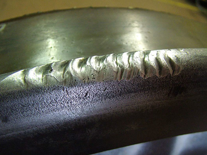
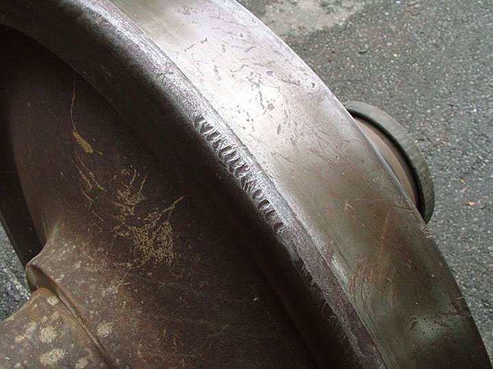
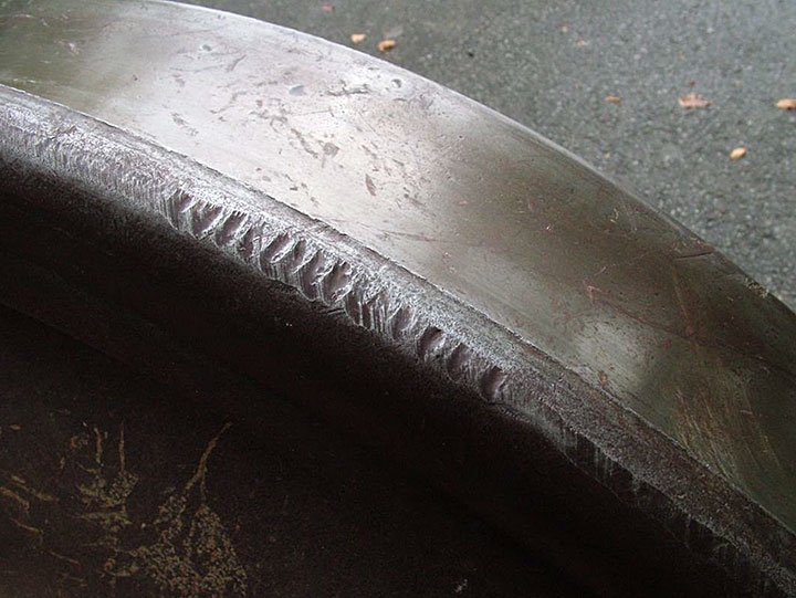
Figure 1 shows the wheel set as received. Both wheels were cleaned so an examination could be performed. The feature observed on the flange of wheel 83414 is shown in Figures 2 through 5. Close-up examination of the feature on the wheel flange revealed that there was a rub mark on either side of it and that its edges were rounded, with a worn appearance.
2.3
Examination of the mating wheel also revealed a similar feature on the wheel flange (Figures 6 and 7). This feature was located approximately 180 degrees from the feature on the subject wheel. Similar to the other wheel, the feature on this wheel had worn edges and an overall worn appearance.
2.4
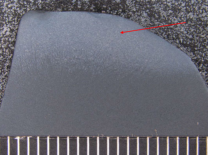
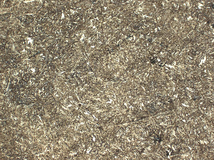
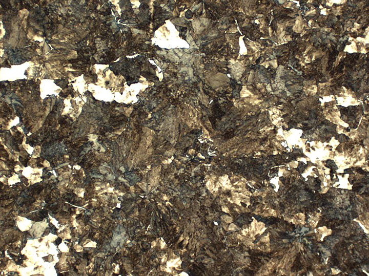
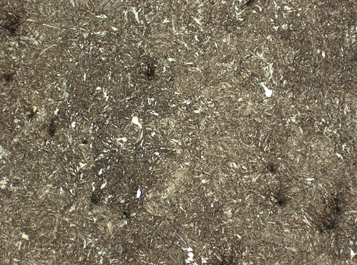
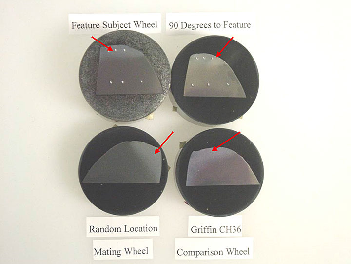
Three metallurgical sections were taken: the first through the middle of the subject wheel flange feature, the second at 90 degrees from the wheel flange feature, and the third from a random location on the wheel flange on the mating wheel. All sections were chemically etched in 2% nital solution. The metallurgical sections showed a zone of fine tempered martensite at the tip of the wheel flange and a core microstructure of ferrite–pearlite (Figures 8 to 13). No sign of welding was observed on the metallurgical section taken through the subject feature. The zone of fine tempered martensite at the tip of the wheel flange is most likely a result of the manufacturing process and would have no effect on the wheel operation or performance.
2.5
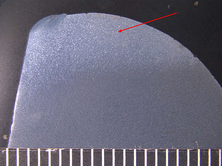
To confirm if this zone of fine tempered martensite at the tip of the wheel flange was an anomaly in this particular wheel set only, a comparison section was taken from another Griffin wheel located at the Engineering Laboratory. The wheel was type CH36, manufactured in March 2011, serial number 06568. Like the subject wheel, the tip of the wheel flange was composed of fine tempered martensite and the core microstructure was ferrite– pearlite. The 4 metallurgical sections are shown in Figure 13. The tip area of the wheel flange which has fine tempered martensite is clearly visible.
2.6
Direct Rockwell C (HRC) hardness testing was performed on the 2 sections from the subject wheel. Readings of 38 to 40 HRC were obtained in the fine tempered martensite region and 35 to 36 HRC in the core. Hardness testing on the section from the mating wheel gave average results of 36 HRC in the fine tempered martensite and 34 HRC in the core. Class C wheels have a Brinell hardness requirement of 321 to 363 HBW,Footnote 1 which is equivalent to 34 to 39 HRC. The hardness results of the core were within the AAR hardness specification for this class of wheel.
2.7
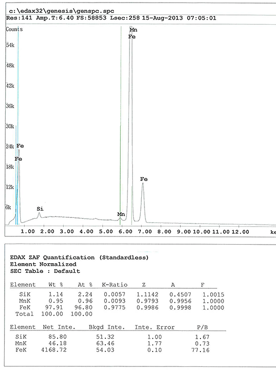
Energy dispersive spectroscopy (EDS) was performed on the metallurgical section taken from the subject wheel and the standard less results show the subject wheel gave manganese and silicon contents consistent with the AAR specification. The amount of carbon, phosphorus, and sulphur could not be measured. A representative spectrum is shown in Figure 14.
2.8
Wheel wear measurements were performed on both wheels and the results are shown in Table 4. Both wheels were within the serviceable limits specified by the AAR.
| Measurement | AAR standard (c ondemning l imit) | Subject wheel | Mating wheel |
|---|---|---|---|
| Flange width (inch) | 15/16 or lessFootnote 2 | >15/16 | >15/16 |
| Rim thickness (inch) | >7/8Footnote 3 | 1 3/8 | 1 9/16 |
| Vertical flange height (inch) | <1Footnote 4 | >1 | >1 |
| Hollow tread wear (mm) | >4Footnote 5 | 3.25 | 0.75 |
3.0 Discussion
3.1
The features observed on the subject and mating wheels were most likely caused by mechanical damage as a result of contact with some foreign object. The rounded edges of the rub marks and their worn surfaces suggest that they were present on the wheel flange for some time and most likely pre-dated this derailment.
3.2
The 2 features observed on the wheel flanges may have been caused by the brake components; they are located very close to the wheel flange and might have contacted the wheel at some point. The other cause might have been contact with some equipment along the track and/or switch.
3.3
The microstructure of the wheel material in the feature areas did not show any changes associated with exposure to heat from processes such as welding or torch cutting.
4.0 Conclusion
4.1
The feature on the subject wheel flange was caused by some type of mechanical damage. The feature had the appearance of being present on the wheel flange for some time and most likely pre-dated the occurrence.
4.2
The mating wheel had a similar type of feature on the wheel flange approximately 180 degrees from the feature on the subject wheel. This feature also appeared to have pre-dated the occurrence.
4.3
The wheel tread wear, flange wear and hollow tread wear were within the AAR specifications.
4.4
Both wheels met the AAR Class C wheel specifications for hardness. No discrepancies were noted with the subject wheel material which met the AAR requirements.
4.5
The metallurgical analysis of the wheel flanges indicated that there was no welding associated with these features.
This lab report is part of the Transportation Safety Board of Canada's investigation report R13D0054.
